Nortek P7RE Series Installation Instructions Manual
Single package air conditioner
Hide thumbs
Also See for P7RE Series:
- Installation instructions manual (20 pages) ,
- Installation instructions manual (20 pages) ,
- Installation instructions manual (20 pages)
Table of Contents
Advertisement
P7RE SERIES
INSTALLATION INSTRUCTIONS
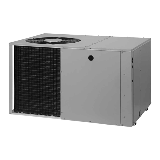
SINGLE PACKAGE AIR CONDITIONER - SINGLE STAGE, R-410A
It is your responsibility to know this product better than your customer. This includes being
able to install the product according to strict safety guidelines and instructing the customer on
how to operate and maintain the equipment for the life of the product. Safety should always be
the deciding factor when installing this product and using common sense plays an important
role as well. Pay attention to all safety warnings and any other special notes highlighted in the
manual. Improper installation of the furnace or failure to follow safety warnings could result in
serious injury, death, or property damage.
These instructions are primarily intended to assist qualified individuals experienced in the proper
installation of this appliance. Some local codes require licensed installation/service personnel
for this type of equipment. Please read all instructions carefully before starting the installation.
Return these instructions to the customer's package for future reference.
DO NOT DESTROY. PLEASE READ CAREFULLY & KEEP IN A SAFE PLACE FOR FUTURE REFERENCE.
IMPORTANT
ATTENTION INSTALLERS:
14 SEER
Advertisement
Table of Contents

Subscribe to Our Youtube Channel
Related Manuals for Nortek P7RE Series


Summary of Contents for Nortek P7RE Series
- Page 1 P7RE SERIES 14 SEER INSTALLATION INSTRUCTIONS SINGLE PACKAGE AIR CONDITIONER - SINGLE STAGE, R-410A IMPORTANT ATTENTION INSTALLERS: It is your responsibility to know this product better than your customer. This includes being able to install the product according to strict safety guidelines and instructing the customer on how to operate and maintain the equipment for the life of the product.
-
Page 2: Table Of Contents
TABLE OF CONTENTS IMPORTANT SAFETY INFORMATION ............. 3 GENERAL INFORMATION ................ 4 Before You Install this Unit ..............4 Locating the Air Conditioner ..............4 Minimum Clearance Requirements ............4 Service Access Clearances ..............4 Clearances to Combustible Materials ..........4 Air Duct System .................. -
Page 3: Important Safety Information
IMPORTANT SAFETY INFORMATION CAUTION: Please read all instructions before servicing this equipment. Pay attention to all safety warnings and any other special This unit uses R-410A refrigerant. DO NOT use notes highlighted in the manual. Safety markings are used any other refrigerant in this unit. Use of another frequently throughout this manual to designate a degree or level of seriousness and should not be ignored. -
Page 4: General Information
GENERAL INFORMATION 24" This packaged air conditioner is designed only for outdoor ground level installations and can be readily connected to the high static duct system of a home. This unit has been tested for capacity and efficiency in accordance with AHRI Standards and will provide many years of safe and dependable comfort, providing it is properly installed and maintained. -
Page 5: Air Conditioner Installation
SINGLE DUCT APPLICATION MULTIPLE DUCT APPLICATION Figure 2. Single & Multiple Duct Applications AIR CONDITIONER INSTALLATION Unpacking the Unit Supply Duct It is recommended that the unit be unpacked at the installation 1. Assemble the collar by overlapping the two ends. site to minimize damage due to handling. -
Page 6: Connecting The Return & Supply Air Flexible Ducts
Figure 5. Supply Damper Figure 4. Return Air Box When locating the supply damper(s), carefully check floor joists and frame members that could interfere with the installation of the through carpeting to avoid snags. NOTE: In most installations damper or flexible duct. Ideally, the damper should be located it will be necessary to cut a similar hole in the fiberboard in the bottom of the main duct, forward of center of the home, directly under the hole in the floor. -
Page 7: Electrical Connections
ELECTRICAL CONNECTIONS WARNING: ELECTRICAL SHOCK, FIRE OR EXPLOSION HAZARD Failure to follow safety warnings exactly could result in serious injury, death or property damage. Improper servicing could result in dangerous operation, serious injury, death or property Line Voltage damage. Low Voltage •... -
Page 8: Cooling Only Thermostat
Blower Speed 2 WIRE COOLING 4 WIRE HEAT/COOL THERMOSTAT For optimum system performance and comfort, it may be (ONLY) THERMOSTAT Single Stage Electric Heat necessary to change the factory speed setting. See Table 2, (page 9) for factory settings. YELLOW YELLOW WARNING: GREEN... -
Page 9: Start-Up Procedure
Start-Up Procedure The control circuit thermostat may consist of an anti-short cycle timer that will not let the compressor re-start before 5 minutes have elapsed. CAUTION: 1. Set the system mode to OFF and the temperature mode to its highest setting. If the unit is equipped with a crankcase heater, 2. -
Page 10: System Cooling
8. Set the temperature mode above room temperature. The unit The compressor is hermetically sealed at the factory and does should stop. not require lubrication. 9. Instruct the homeowner on unit and thermostat operation and filter servicing. REFRIGERANT CHARGING Air Circulation Charging the Unit Leave the thermostat system mode on OFF, and set the fan (with Outdoor Temperatures Above 65°... -
Page 11: Refrigerant Charging Tables
Refrigerant Charging Tables NOTES: LEGEND Shaded boxes indicate flooded conditions. 1. All pressures are listed psig and all temperatures in °F Rated design values. The suction pressure 2. Discharge temperatures greater than charted values indicate will vary from design value if outdoor air an undercharged system. - Page 12 OUTDOOR TEMPERATURE (° F) SUCT. PRESS. LIQ. DIS. LIQ. DIS. LIQ. DIS. LIQ. DIS. LIQ. DIS. LIQ. DIS. LIQ. DIS. LIQ. DIS. PRESS. TEMP. PRESS. TEMP. PRESS. TEMP. PRESS. TEMP. PRESS. TEMP. PRESS. TEMP. PRESS. TEMP. PRESS. TEMP. Table 5. Charging Table for 2.5 Ton Units (030K Model) OUTDOOR TEMPERATURE (°...
- Page 13 OUTDOOR TEMPERATURE (° F) SUCT. PRESS. LIQ. DIS. LIQ. DIS. LIQ. DIS. LIQ. DIS. LIQ. DIS. LIQ. DIS. LIQ. DIS. LIQ. DIS. PRESS. TEMP. PRESS. TEMP. PRESS. TEMP. PRESS. TEMP. PRESS. TEMP. PRESS. TEMP. PRESS. TEMP. PRESS. TEMP. Table 7. Charging Table for 3.5 Ton Units (042K Model) INDOOR WET-BULB TEMPERATURE (°F) 26.6...
- Page 14 P7RE-060KA Charging Chart-Cooling Remove refrigerant when above curve Add refrigerant when below curve Liquid Temperature ( ° F ) Figure 9. Charging Chart for 5 Ton Units (X60KA Model)
-
Page 15: Figures & Tables
FIGURES & TABLES Top View “A” “B” 3” 5.5” Opening for Opening for 12" Diameter 12" Diameter Supply Duct Return Duct 9.15” 1" 3.15” 9” 17.50” Rear View (1.5, 2, 2.5, & 3 Ton) 1.75” Ø Electric Heater Power Supply 1.13”... -
Page 16: Wiring Diagrams
Wiring Diagrams Figure 11. Wiring Diagram (1.5, 2, & 2.5 Ton Models) - Page 17 Figure 12. Wiring Diagram (3, 3.5, 4, & 5 Ton Models)
-
Page 20: Installation Checklist
Fan Motor COMPONENTS: • Blower Assembly • Fan Grille • Cabinet Panels • Filter/Driers • Expansion Valves 1033141A Specifications & illustrations subject to change without notice or incurring obligations (12/20). (Replaces 10331410) © Nortek Global HVAC LLC 2020. All Rights Reserved.
Need help?
Do you have a question about the P7RE Series and is the answer not in the manual?
Questions and answers
What size air filter