Table of Contents
Advertisement
Quick Links
Download this manual
See also:
Instruction Manual
Advertisement
Table of Contents

Related Manuals for Basler BE1-47N


Summary of Contents for Basler BE1-47N
- Page 1 INSTRUCTION MANUAL VOLTAGE PHASE SEQUENCE RELAY BE1-47N Publication: 9 1704 00 990 Revision: F 02/01...
- Page 2 INTRODUCTION This Instruction Manual provides information concerning the operation and installation of BE1-47N Voltage Phase Sequence Relay. To accomplish this, the following is provided. Specifications Functional characteristics Installation Operational Tests Mounting Information WARNING To avoid personal injury or equipment damage, only qualified personnel should perform the procedures presented in this manual.
- Page 3 February 2001 CONFIDENTIAL INFORMATION OF BASLER ELECTRIC COMPANY, HIGHLAND, IL. IT IS LOANED FOR CONFIDENTIAL USE, SUBJECT TO RETURN ON REQUEST, AND WITH THE MUTUAL UNDERSTANDING THAT IT WILL NOT BE USED IN ANY MANNER DETRIMENTAL TO THE INTEREST OF BASLER ELECTRIC COMPANY.
-
Page 4: Table Of Contents
Changes ............7-1 BE1-47N Introduction... -
Page 5: General Information
The effect of this condition can be costly. BE1-47N relays can be applied to protect motor buses from an open phase. It can also be applied to protect critical individual motors, static, and nonrotating loads from the effects of negative sequence voltage. -
Page 6: Model And Style Number
Style number identification chart (Figure 1-1) defines the electrical characteristics and operational features included in BE1-47N relays. For example, if the model number of the relay was BE1-47N, and the style number was E3F-E1P-A1R0F the device would have the following features:... -
Page 7: Specifications
Adjustable over the range of 2 to 32% Pickup in increments of 2%. Pickup accuracy is within +1 unit of the percent setting of the negative sequence voltage at nominal frequency (50 or 60 hertz as defined by the style number). Negative Sequence Voltage 98% of pickup Dropout BE1-47N General Information... - Page 8 Inverse Time: Adjustable over the range of 01 to 99 in increments of 1. Accuracy within +5% or +50 ms (whichever is greater of the indicated time of the selected time-dial curve as plotted in Figure 3-5. Instantaneous Time: Less than 50 ms. BE1-47N General Information...
- Page 9 Qualified to IEC 255-5. Temperature -40 C (-40 F) to 70 C (158 F) Operating -65 C (-85 F) to 100 C (212 F) Storage Weight 14.0 pounds Case Size BE1-47N General Information...
-
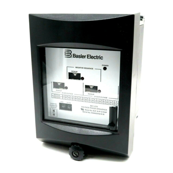
Page 10: Human-Machine Interface (Controls And Indicators)
47N Target Indicator Red target indicates when negative sequence voltage output relay has energized. Must be manually reset. BE1-47N Human-Machine Interface (Controls and Indicators) - Page 11 OVERVOLTAGE pickup setting. OVERVOLTAGE TIME DELAY Thumbwheel switch provides adjustment of inverse, definite, or instantaneous TIME DELAY for the Overvoltage function (See Specifications for ranges and accuracies.) Figure 2-1. Location of Controls and Indicators BE1-47N Human-Machine Interface (Controls and Indicators)
-
Page 12: Functional Description
PICKUP SCALING The resolved negative sequence voltage (V ) ac signal is then applied to the PICKUP scaling network (switch S1 and its associated resistors). The PICKUP network establishes per unit (p.u.) values of V for the BE1-47N Functional Description... -
Page 13: Low-Pass Filter
TARGETS Magnetically latched, manually reset target indicators are optionally available for the functions and may be either internally operated (signal operated) or current operated (operated by a minimum of 0.2 Adc through the output trip circuit). BE1-47N Functional Description... - Page 14 BE1-47N Functional Description...
-
Page 15: Power Supply
POWER SUPPLY STATUS OUTPUT The power supply status output is a standard feature of the BE1-47N relay. The power supply status output relay has a set of normally closed (NC) contacts that are energized open upon power-up and remain open during proper power supply operation. - Page 16 M U L T I P L E S O F P I C K - U P S E T T I N G 1 0 0 0 5 0 0 1 0 0 D2818-17 MULTIPLES OF PICK-UP SETTING 07-31-98 Figure 3-2. Negative Sequence Voltage Inverse Time Characteristic Curves BE1-47N Functional Description...
- Page 17 D2818-15 07-31-98 Figure 3-3. Undervoltage Inverse Time Characteristic Curves BE1-47N Functional Description...
- Page 18 D2818-16 07-31-98 Figure 3-4. Overvoltage Inverse Time Characteristic Curves BE1-47N Functional Description...
-
Page 19: Installation
If there is evident damage, immediately file a claim with the carrier and notify the Regional Sales Office, or contact the Sales Representative at Basler Electric, Highland, Illinois. In the event the relay is not to be installed immediately, store the relay in its original shipping carton in a moisture and dust free environment. - Page 20 Figure 4-1. S1 Case, Panel Drilling Diagram, Semi-Flush Mounting D1427-01 2-02-01 Figure 4-2. S1 Case, Outline Dimensions, Front View BE1-47N Installation...
- Page 21 Figure 4-3. S1 Case, Single-Ended, Semi-Flush Mounting, Outline Dimensions, Side View DETAIL A-A OVER THE BOSS TO TIGHTEN THE D 1 4 2 7 - 0 3 02/2001 Figure 4-4. S1 Case, Single-Ended, Projection Mounting, Outline Dimensions, Side View BE1-47N Installation...
- Page 22 Figure 4-5. S1 Case, Double-Ended, Semi-Flush Mounting, Outline Dimensions, Side View DETAIL A-A OVER THE BOSS TO TIGHTEN THE D 1 4 2 7 - 0 3 02/2001 Figure 4-6. S1 Case, Double-Ended, Projection Mounting, Outline Dimensions, Side View BE1-47N Installation...
- Page 23 Figure 4-7. S1 Case, Single-Ended, Panel Drilling Diagram, Rear View BE1-47N Installation...
- Page 24 Figure 4-8. S1 Case, Double-Ended, Panel Drilling Diagram, Rear View BE1-47N Installation...
- Page 25 Figure 4-9. Semi-Flush Mounting, Outline Dimensions, Rear View BE1-47N Installation...
- Page 26 Figure 4-10. S1 Case, Projection Mounting, Outline Dimensions, Rear View BE1-47N Installation...
-
Page 27: Connections
Except as noted above, connections should be made with minimum wire size of 14 AWG. Figure 4-11. Control Circuit Diagram BE1-47N Installation... - Page 28 Figure 4-12. Sensing Input Connections 4-10 BE1-47N Installation...
- Page 29 Figure 4-13. Typical Internal Connection Diagram with Optional Output Contacts, Normally Open 4-11 BE1-47N Installation...
-
Page 30: General
Negative Sequence Voltage Pickup and Dropout To fully test the designed-in accuracy of the BE1-47N relay requires a simultaneous test of the three phases. Such a comprehensive test involves careful monitoring of all phase voltages and phase angles, and the calculation of the negative sequence voltages values. - Page 31 (with Phase B shorted to Phase C) For 120V Nominal V (0.2) ( 3) (120) 41.569 Vac when Phase Input B is shorted to C STEP 6. Test the other phases by repeating the previous steps while shorting different phase-pairs. BE1-47N Testing...
-
Page 32: Overvoltage Pickup And Dropout
Negative Sequence Time Delay - 10 STEP 3. Short or jumper case terminal #7 (phase B) to #8 (phase C). STEP 4. Apply the following input voltage from terminal #6 (phase A) to #7 (phase B and C) according to BE1-47N Testing... - Page 33 RESULT: 47N Inverse Time should be 5.96 +0.298 seconds. Further points on the inverse time curves may be verified using the same philosophy. Input voltage values for pickup may be obtained using the formulas mentioned previously. Figure 5-1. Test Circuit Diagram (47N) BE1-47N Testing...
- Page 34 Figure 5-2. Test Circuit Diagram (27, 59) BE1-47N Testing...
-
Page 35: Maintenance
SECTION 6 • MAINTENANCE GENERAL Basler relays are static devices which require no preventive maintenance other than a periodic operational check. If the relay fails to function properly, contact the Customer Service Department of the Power Systems Group, Basler Electric, for a return authorization number prior to shipping the relay. -
Page 36: Manual Change Information
T from “230 Vac” to “240 Vac” and deleting from Target Option N) None. Added new power supply information to Section 3 in Power Supply paragraph starting with “Basler Electric enhanced the power supply design...”. Added new dimension figures to include all options available (S1 Single- Ended and Double-Ended, and both mounting positions).
Need help?
Do you have a question about the BE1-47N and is the answer not in the manual?
Questions and answers