Table of Contents
Advertisement
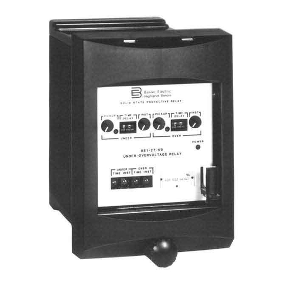
INSTRUCTION MANUAL
UNDERVOLTAGE, OVERVOLTAGE,
UNDER/OVERVOLTAGE RELAYS
BE1-27, BE1-59, BE1-27/59
PICKUP
INST
OVER
TIME
INST
UNDER
TIME
FOR
TIME
DELAY
INST
PICKUP
UNDER
BE1-27/59
UNDER/OVER VOLTAGE RELAY
Style No. A3F E1J A4S3F
R
Serial No. H12345678910
UNDER
OVER
TIME
INST
TIME
INST
CAUTION: UPPER CONNECTION PLUG MUST BE REMOVED
PRIOR TO REMOVING LOWER CONNECTION PLUG.
TIME
DELAY
INST
OVER
POWER
P0050-48
Publication: 9170600990
Revision: H
02/08
Advertisement
Table of Contents

Related Manuals for Basler BE1-27


Summary of Contents for Basler BE1-27
- Page 1 INSTRUCTION MANUAL UNDERVOLTAGE, OVERVOLTAGE, UNDER/OVERVOLTAGE RELAYS BE1-27, BE1-59, BE1-27/59 TIME TIME PICKUP DELAY INST PICKUP DELAY INST UNDER OVER BE1-27/59 POWER UNDER/OVER VOLTAGE RELAY Style No. A3F E1J A4S3F Serial No. H12345678910 UNDER OVER TIME INST TIME INST INST OVER...
- Page 3 INTRODUCTION This instruction manual provides information about the operation and installation of the BE1-27 Undervoltage Relay, the BE1-59 Overvoltage Relay, and the BE1-27/59 Under/Overvoltage Relay. To accomplish this, the following information is provided: • General Information and Specifications • Controls and Indicators •...
- Page 4 February 2008 CONFIDENTIAL INFORMATION of Basler Electric, Highland Illinois, USA. It is loaned for confidential use, subject to return on request, and with the mutual understanding that it will not be used in any manner detrimental to the interest of Basler Electric.
- Page 5 REVISION HISTORY The following information provides a historical summary of the changes made to the BE1-27, BE1-59, and BE1-27/59 instruction manual (9170600990). Revisions are listed in reverse chronological order. Manual Revision and Date Change • H, 02/08 Consolidated sensing input range options in style chart of Figure 1-2 to cover all relay models.
- Page 6 This page intentionally left blank. BE1-27/29 Introduction 9170600990 Rev H...
-
Page 7: Table Of Contents
CONNECTIONS..........................4-14 MAINTENANCE ..........................4-19 STORAGE............................4-19 SECTION 5 • TESTING ..........................5-1 INTRODUCTION..........................5-1 REQUIRED TEST EQUIPMENT ......................5-1 OPERATIONAL TEST ........................5-1 Power Supply Status Output ......................5-1 Pickup ............................5-1 Timing ............................5-4 9170600990 Rev H BE1-27/59 Introduction... - Page 8 This page intentionally left blank. BE1-27/29 Introduction 9170600990 Rev H...
-
Page 9: Section 1 • General Information
During motor start-up, a low terminal voltage condition will inhibit the motor from reaching rated speed. The BE1-27 Undervoltage Relay will detect this low voltage condition and trip. Critical applications requiring continuous motor operation and applications where overloads during start-up may be maintained for a given time period, usually have a definite time or inverse time delay characteristic incorporated to avoid unnecessary tripping during low voltage dips. -
Page 10: Transformer Protection
BE1-27, BE1-59, and BE1-27/59 electrical characteristics and operational features are defined by a combination of letters and numbers that make up the style number. Model number BE1-27/59 designates the relay as a Basler Electric Under/Overvoltage Protective Relay. The model number, together with the style number, describes the options included in a specific device and appears on the front panel, draw-out cradle, and inside the case assembly. - Page 11 Figure 1-2. Style Number Identification Chart 9170600990 Rev H BE1-27/59 General Information...
-
Page 12: Style Number Example
Style Number Example If a BE1-27/59 relay has a style number of A3F–E1J–A0S1F, the relay has the following features: A ------- Single-phase voltage sensing input 3-------- Sensing input compatible with a pickup adjustment range of 55 to 160 Vac F-------- Two normally open output relays (one per function) -
Page 13: Output Contacts
Tested in accordance with IEC 255-5 and IEEE C37.90: 2,000 Vac applied for 1 min Impulse Test: Qualified to IEC 255-5 Radio Frequency Interference: Qualified to IEEE C37.90.2-1995, Standard for Withstand Capability of Relay Systems to Radiated Electromagnetic Interference from Transceivers. 9170600990 Rev H BE1-27/59 General Information... -
Page 14: Physical
NOTE: Output contacts are not UL recognized for voltages greater than 250 volts. Gost-R Certification: Gost-R certified, No. POCC US.ME05.B03391; complies with the relevant standards of Gosstandart of Russia. Issued by accredited certification body POCC RU.0001.11ME05. BE1-27/59 General Information 9170600990 Rev H... -
Page 15: Section 2 • Controls And Indicators
1 and described in Table 2-1. Figure 2-1 illustrates a relay with the maximum number of controls and indicators. Your relay may not have all of the controls and indicators shown and described here. Figure 2-1. Location of Controls and Indicators 9170600990 Rev H BE1-27/59 Controls and Indicators... - Page 16 Output Test Pushbuttons. These pushbuttons allow manual actuation of the output relays. Output relay actuation is achieved by inserting a nonconductive rod through the front panel access holes. Undervoltage Pickup LED. A red LED that illuminates when undervoltage exceeds the pickup setting. BE1-27/59 Controls and Indicators 9170600990 Rev H...
-
Page 17: Section 3 • Functional Description
SECTION 3 • FUNCTIONAL DESCRIPTION INTRODUCTION BE1-27, BE1-59, and BE1-27/59 relay functions are illustrated in Figure 3-1 and described in the following paragraphs. PICKUP SETTINGS INST. TIMED OV TIME OVER UNDER OVER UNDER DIAL AUX. TIMED TIMER COMPARATOR TARGET AUX. -
Page 18: Step-Down Transformer
This response is illustrated in the characteristic curves as shown in Figures 3-2 through 3-7. BE1-27/59 Functional Description 9170600990 Rev H... - Page 19 Figure 3-2. Undervoltage, Short Inverse Timing Characteristic Curve 1000 Range 2 Range 3 Range 4 D2857-24.vsd Voltage Difference From Pickup 11-22-99 Figure 3-3. Undervoltage, Medium Inverse Timing Characteristic Curve 9170600990 Rev H BE1-27/59 Functional Description...
- Page 20 1000 Range 3 Range 4 D2857-25 Voltage Difference From Pickup 06-09-03 Figure 3-4. Undervoltage, Long Inverse Timing Characteristic Curve Figure 3-5. Overvoltage, Short Inverse Timing Characteristic Curve BE1-27/59 Functional Description 9170600990 Rev H...
- Page 21 Voltage Difference From Pickup D2750-15 06-19-03 Figure 3-6. Overvoltage, Medium Inverse Timing Characteristic Curve 1000.0 100.0 10.0 Range 2 Range 3 Range 4 D2750-16 Voltage Difference From Pickup 06-19-03 Figure 3-7. Overvoltage, Long Inverse Timing Characteristic Curve 9170600990 Rev H BE1-27/59 Functional Description...
-
Page 22: Outputs
200 milliamperes of current flowing in the trip circuit. NOTE Prior to September 2007, BE1-27/59 target indicators consisted of magnetically latched, disc indicators. These mechanically latched target indicators have been replaced by the electronically latched LED targets in use today. -
Page 23: Section 4 • Installation
If there is evidence of damage, file a claim with the carrier, and notify your sales representative or Basler Electric. If the relay will not be installed immediately, store it in its original shipping carton in a moisture- and dust- free environment. - Page 24 Figure 4-1. Panel Cutting/Drilling, Semi-Flush Case BE1-27/59 Installation 9170600990 Rev H...
- Page 25 Figure 4-2. Panel Cutting/Drilling, Double-Ended Projection-Mount Case 9170600990 Rev H BE1-27/59 Installation...
- Page 26 Figure 4-3. Panel Cutting/Drilling, Single-Ended Projection-Mount Case BE1-27/59 Installation 9170600990 Rev H...
- Page 27 D1427-27 12-04-01 Figure 4-4. Case Dimensions, Side View, Double-Ended Semi-Flush Case 9170600990 Rev H BE1-27/59 Installation...
- Page 28 Figure 4-5. Case Dimensions, Side View, Double-Ended Projection-Mount Case BE1-27/59 Installation 9170600990 Rev H...
- Page 29 Figure 4-6. Case Dimensions, Side View, Single-Ended Semi-Flush Case 9170600990 Rev H BE1-27/59 Installation...
- Page 30 Figure 4-7. Case Dimensions, Side View, Single-Ended Projection-Mount Case BE1-27/59 Installation 9170600990 Rev H...
- Page 31 Figure 4-8. Case Dimensions, Rear View, Double-Ended, Semi-Flush Case 9170600990 Rev H BE1-27/59 Installation...
- Page 32 Figure 4-9. Case Dimensions, Rear View, Double-Ended, Projection-Mount Case 4-10 BE1-27/59 Installation 9170600990 Rev H...
- Page 33 Figure 4-10. Case Dimensions, Rear View, Double-Ended, Semi-Flush Case 9170600990 Rev H BE1-27/59 Installation 4-11...
- Page 34 Figure 4-11. Case Dimensions, Rear View, Double-Ended, Projection-Mount Case 4-12 BE1-27/59 Installation 9170600990 Rev H...
- Page 35 P0002-12 01-31-01 Figure 4-12. Case Cover Dimensions, Front View 9170600990 Rev H BE1-27/59 Installation 4-13...
-
Page 36: Connections
14 AWG. Typical internal connections are shown in Figures 4-13 through 4-15. Typical ac connections are shown in Figure 4-16. Typical dc connections are shown in Figure 4-17. Figure 4-13. BE1-27 Internal Connections 4-14 BE1-27/59 Installation... - Page 37 Figure 4-14. BE1-59 Internal Connections 9170600990 Rev H BE1-27/59 Installation 4-15...
- Page 38 Figure 4-15. BE1-27/59 Internal Connections 4-16 BE1-27/59 Installation 9170600990 Rev H...
- Page 39 Figure 4-16. Typical AC Connections 9170600990 Rev H BE1-27/59 Installation 4-17...
- Page 40 Figure 4-17. Typical DC Connections 4-18 BE1-27/59 Installation 9170600990 Rev H...
-
Page 41: Maintenance
MAINTENANCE BE1-27, BE1-59, and BE1-27/59 relays require no preventative maintenance other than a periodic operational check. If the relay fails to function properly, contact Technical Sales Support at Basler Electric to coordinate repairs. STORAGE This protective relay contains aluminum electrolytic capacitors which generally have a life expectancy in excess of 10 years at storage temperatures less than 40°C (104°F). - Page 42 This page intentionally left blank. 4-20 BE1-27/59 Installation 9170600990 Rev H...
-
Page 43: Section 5 • Testing
Sensing Input Range 120 Vac 120 Vac 240 Vac NOTE Results assume normally open output contacts. Test indicator states will be opposite for normally closed output contacts. 9170600990 Rev H BE1-27/59 Testing... - Page 44 Figure 5-1. Pickup and Dropout Test Circuit Diagram Figure 5-2. Timing Test Circuit Diagram BE1-27/59 Testing 9170600990 Rev H...
- Page 45 This voltage is between 156.8 and 163.2 Vac for Sensing Input Range 3 or between 313.6 and 326.4 for Sensing Input Range 4. This concludes the pickup test for the undervoltage functions. NOTE Steps 7 and 8 apply only to overvoltage functions. 9170600990 Rev H BE1-27/59 Testing...
-
Page 46: Timing
51.895 to 57.358 sec Step 4. Set the time delay control for the function being tested to 01 (0.1 seconds). Press and release S2 to assure that K1 is de-energized. Reset the timer. Press and release S1. BE1-27/59 Testing 9170600990 Rev H... - Page 47 The timer displays a response time, dependent on timing type, as indicated in Column 2 of Table 5-3. Step 6. Repeat Steps 1 through 5, as necessary, for each function’s time delay control. This concludes the operational test procedure. 9170600990 Rev H BE1-27/59 Testing...
- Page 48 This page intentionally left blank. BE1-27/59 Testing 9170600990 Rev H...
- Page 49 ROUTE 143, BOX 269 HIGHLAND, IL 62249 USA http://www.basler.com, info@basler.com PHONE +1 618-654-2341 FAX +1 618-654-2351...
Need help?
Do you have a question about the BE1-27 and is the answer not in the manual?
Questions and answers