Table of Contents
Advertisement
Quick Links
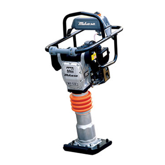
PARTS AND OPERATION MANUAL
Tamping Rammer
Model MT55-F
Revision #0 (07/03/02)
MULTIQUIP INC. . . . .
18910 WILMINGTON AVE.
CARSON, CALIFORNIA 90746 FAX: 800-672-7877
310-537-3700
800-421-1244
FAX: 310-537-3927
E-mail:mq@multiquip.com
Atlanta • Boise • Dallas • Houston • Newark
Montreal, Canada • Manchester, UK
Rio De Janiero, Brazil • Guadalajara, Mexico
PARTS DEPARTMENT:
800-427-1244
SERVICE DEPARTMENT/TECHNICAL ASSISTANCE:
800-478-1244
FAX: 310-631-5032
•
www:multiquip.com
Advertisement
Table of Contents

Related Manuals for MULTIQUIP mikasa mt55-f


Summary of Contents for MULTIQUIP mikasa mt55-f
- Page 1 PARTS AND OPERATION MANUAL Tamping Rammer Model MT55-F Revision #0 (07/03/02) MULTIQUIP INC..PARTS DEPARTMENT: 18910 WILMINGTON AVE. 800-427-1244 CARSON, CALIFORNIA 90746 FAX: 800-672-7877 SERVICE DEPARTMENT/TECHNICAL ASSISTANCE: 310-537-3700 800-421-1244 800-478-1244 FAX: 310-537-3927 FAX: 310-631-5032 • E-mail:mq@multiquip.com www:multiquip.com...
- Page 2 PAGE 2 — MT55-F — PARTS & OPERATION MANUAL — REV. #0 (07/03/02)
-
Page 3: Here's How To Get Help
HERE'S HOW TO GET HELP PLEASE HAVE THE MODEL AND SERIAL NUMBER ON-HAND WHEN CALLING PARTS DEPARTMENT 800-427-1244 or 310-537-3700 FAX: 800-672-7877 or 310-637-3284 SERVICE DEPARTMENT/TECHNICAL ASSISTANCE 800-478-1244 or 310-537-3700 FAX: 310- 537-4259 WARRANTY DEPARTMENT 888-661-4279, or 310-661-4279 FAX: 310- 537-1173 MAIN 800-421-1244 or 310-537-3700 FAX: 310-537-3927... -
Page 4: Table Of Contents
TABLE OF CONTENTS Here's How To Get Help ..........3 ROBIN EH-09 STD ENGINE Table Of Contents .............4 Crankcase Assembly ......... 38-39 Parts Ordering Procedures ........5 Crankshaft and Piston Assembly ....... 40-41 Safety Message Alert Symbols ......6-7 Intake and Exhaust Assembly ......42-43 Rules For safe Operation ........ -
Page 5: Parts Ordering Procedures
PARTS ORDERING PROCEDURES Dealer account number Dealer name and address Shipping address (if different than billing address) Return fax number Applicable model number Quantity, part number and description of each part Specify preferred method of shipment: • UPS Ground • UPS Second Day or Third Day* •... -
Page 6: Safety Message Alert Symbols
This Owner's Manual has been developed to provide provide ample free flow air. complete instructions for the safe and efficient operations of the MQ Mikasa MT55-F Tamping Rammer. Refer to the engine manufacturers instructions for data relative to its safe operation. - Page 7 MT55-F — SAFETY MESSAGE ALERT SYMBOLS Accidental Starting Respiratory Hazard ALWAYS place the ON/OFF switch in the OFF position, disconnect the spark plug lead before ALWAYS wear approved respiratory servicing the engine or equipment. Ground protection. the lead to prevent sparks that could ignite a fire.
-
Page 8: Rules For Safe Operation
MT55-F — RULES FOR SAFE OPERATION CAUTION: NEVER use accessories or attachments, which are not recommended by Multiquip for this equipment. Damage to Failure to follow instructions in this manual the equipment and/or injury to user may result. may lead to serious injury or even death! -
Page 9: Rules For Safe Operation
Equipment should be stored in a clean, dry location out of the reach of children. Refer to the ROBIN Engine Owner's Manual for engine technical questions or information recommended by Multiquip for this equipment. Damage to the equipment and/or injury to user may result. -
Page 10: Operation And Safety Decals
MT55-F — OPERATION AND SAFETY DECALS PAGE 10 — MT55-F — PARTS & OPERATION MANUAL — REV. #0 (07/03/02) -
Page 11: General Information
Construction of Tamping Rammer The Mikasa MT55-F is equipped with an air cooled, two cycle gasoline engine. Transmission of the power takes place by increasing the engine speed to engage the centrifugal clutch. -
Page 12: Specifications
MT55-F — SPECIFICATIONS c i f i t a s s s s s l l a . n i l l a . n i o r t ) t h . t f ) n i b / . t u l c i t f i r t... -
Page 13: Controls And Components
11. Nameplate – Displays information regarding the rammer. Foot – Laminated wood with tempered steel plate for L1. A Returned Material Authorization must be approved by Multiquip prior to shipment. A copy of the Authorization must 12. Engine Air Cleaner – Prevents dirt (second stage) and superior shock absorption. -
Page 14: Basic Engine
MT55-F — BASIC ENGINE Figure 2. Engine Controls and Components INITIAL SERVICING The engine (Figure 2) must be checked for proper lubrication and Recoil Starter (pull rope) – Manual-starting method. Pull the starter grip until resistance is felt, then pull briskly and filled with fuel prior to operation. - Page 15 MT55-F — OPERATION Fuel This section is intended to assist the operator with the initial start-up of the MT55-F Tamping Rammer. It extremely important 1. Fill the fuel tank (Figure 4) with unleaded gasoline. DO NOT that this section be read carefully before attempting to operate overfill, wipe up spilled fuel immediately.
- Page 16 MT55-F — OPERATION Initial Start-up When starting the MT55-F Tamping Rammer perform the following: Open the fuel shut- off valve by moving the fuel cock lever to the open position (Figure 7). Figure 6. Engine Oil Dipstick (Oil Level) r o t l i o i h ( s a l...
-
Page 17: Operation
MT55-F — OPERATION Figure 9. Throttle Lever (Idle) Figure 11. Recoil Starter 4. In cold weather, start the unit with choke lever "Fully Closed"(Figure 10). In warm weather or when the engine is warm, the unit can be started with choke halfway or com- 6. - Page 18 MT55-F — OPERATION CAUTION: CAUTION: CAUTION: CAUTION: CAUTION: 2. After the engine cools , turn the engine start/stop switch to the “OFF” position (Figure 14). Make sure that the throttle lever is moved to the FULL OPEN position. Operating the rammer at less than full speeds can result in damage to the clutch springs or foot 2.
-
Page 19: Maintenance
MT55-F — MAINTENANCE Maintenance Perform the scheduled maintenance procedures as indicated: PAPER ELEMENT DAILY GRAY OUTER FOAM ELEMENT Thoroughly remove dirt and oil from the engine and control area. Clean or replace the air cleaner elements as necessary. Check and retighten all fasteners as necessary. Check the spring box and bellows for oil leaks. -
Page 20: Troubleshooting Guide
MT55-F — TROUBLESHOOTING GUIDE c i f t l u t r a i t i n i r b i t i n i s o o i t i c a l o i t i l i a l i w . - Page 21 MT55-F — TROUBLESHOOTING GUIDE ENGINE ENGINE ENGINE ENGINE ENGINE i t n i t a f s i e r r v e l . r e i r p v i t o i t o i t u l f l f l r r e i t a...
-
Page 22: Explanation Of Codes In Remarks Column
EXPLANATION OF CODE IN REMARKS COLUMN How to read the marks and remarks used in this parts book. Items Found In the “Remarks” Column NOTE Serial Numbers-Where indicated, this indicates a serial number range (inclusive) where a particular part is used. Model Number-Where indicated, this shows that the The contents of this corresponding part is utilized only with this specific model... -
Page 23: Suggested Spare Parts
MT55-F— SUGGESTED SPARE PARTS MT55-F RAMMER 3TO 5 UNITS WITH ROBIN MT55-F RAMMER 1 TO 3 UNITS WITH ROBIN EH-09 STD ENGINE EH-09 STD ENGINE Qty. Description Qty. Description 1 .... 362910060 .... LEVER, THROTTLE 1 .... 362910060 .... LEVER, THROTTLE 1 .... -
Page 24: Name Plate And Decals
MT55-F— NAMEPLATE AND DECALS NAME PLATE AND DECALS PAGE 24 — MT55-F — PARTS & OPERATION MANUAL — REV. #0 (07/03/02) -
Page 25: Name Plate And Decals
MT55-F— NAMEPLATE AND DECALS NAME PLATE AND DECALS PART NO PART NAME QTY. REMARKS 920106460 DECAL: MIKASA LOGO 920203290 DECAL: READ MANUAL ......1 .... NPA-329 DCL205 DECAL: GASOLINE ONLY NPA975 DECAL: CAUTION/OPERATION NPA831 DECAL: NOTICE NPA963 DECAL: CLEANING ELEMENT DECAL: NAMEPLATE ........ -
Page 26: Crankcase And Engine Assembly
MT55-F — CRANKCASE AND ENGINE ASSY. CRANKCASE AND ENGINE ASSY. PAGE 26 — MT55-F — PARTS & OPERATION MANUAL — REV. #0 (07/03/02) - Page 27 MT55-F — CRANKCASE AND ENGINE ASSY. CRANKCASE AND ENGINE ASSY. PART NO. PART NAME QTY. REMARKS 362116510 CRANK CASE 362341650 CRANK GEAR 1300-59Z 040006305 BEARING 6305 040006203 BEARING 6203 952401450 WASHER 8.5X22X3 001220825 BOLT 8X25 T 030208200 SW M8 362455660 BEARING COVER 050100350 O-RING G-35...
- Page 28 MT55-F — CRANKCASE AND ENGINE ASSY. CRANKCASE AND ENGINE ASSY. PAGE 28 — MT55-F — PARTS & OPERATION MANUAL — REV. #0 (07/03/02)
- Page 29 MT55-F — CRANKCASE AND ENGINE ASSY. CRANKCASE AND ENGINE ASSY. PART NO. PART NAME QTY. REMARKS 2741600113 STIFFENER 0011408250 BOLT & WASHER 0011408300 BOLT & WASHER ASSY. 362116870 AIR CLEANER ASSY........1 ..... INCLUDES ITEMS W/ 44-1 362030010 COVER CP, AIR CLEANER 44-2 362030020 PACKING, AIR CLEANER...
-
Page 30: Guide Cylinder And Foot Assembly
MT55-F — GUIDE CYLINDER ASSY. GUIDE CYLINDER ASSY. PAGE 30 — MT55-F — PARTS & OPERATION MANUAL — REV. #0 (07/03/02) - Page 31 MT55-F — GUIDE CYLINDER ASSY. GUIDE CYLINDER ASSY. PART NO. PART NAME QTY. REMARKS 351420390 PISTON PIN 080100120 STOP RING R-12 351324120 PISTON ROD 362455680 PISTON END 020116130 NUT M16, P1.5 351434200 STOPPER, UPPER 351434211 STOPPER, LOWERD:30 362452830 MAIN SPRING, A,B 362341640 SPRING CYLINDER 362214820...
-
Page 32: Foot Assembly
MT55-F — FOOT ASSY. FOOT ASSY. PAGE 32 — MT55-F — PARTS & OPERATION MANUAL — REV. #0 (07/03/02) - Page 33 MT55-F — FOOT ASSY. FOOT ASSY. PART NO. PART NAME QTY. REMARKS 362910050 FOOT ASSY. 265 ......1 ......INCLUDES ITEMS W/ 022711214 NYLON NUT M12 030212300 SW M12 001611051 SUNK HEAD BOLT 10x55 030210250 SW M10 022711012 NYLON NUT M10 362341760 FOOT 265W 362341770...
-
Page 34: Tank And Handle Assembly
MT55-F — TANK AND HANDLE ASSY. TANK AND HANDLE ASSY. PAGE 34 — MT55-F — PARTS & OPERATION MANUAL — REV. #0 (07/03/02) - Page 35 MT55-F — TANK AND HANDLE ASSY. TANK AND HANDLE ASSY. PART NO. PART NAME QTY. REMARKS 305910031 F.TANK AY 2L (GRAY) ........1 ..... INCLUDES ITEMS W/ 362910060 THROTTLE LEVER ASSY......1 ..... INCLUDES ITEMS W/ 362341550 THROTTLE BODY 362455610 THROTTLE GEAR 362455620...
- Page 36 MT55-F — TANK AND HANDLE ASSY. TANK AND HANDLE ASSY. PAGE 36 — MT55-F — PARTS & OPERATION MANUAL — REV. #0 (07/03/02)
- Page 37 MT55-F — TANK AND HANDLE ASSY. TANK AND HANDLE ASSY. PART NO. PART NAME QTY. REMARKS 954406000 FUEL COCK ASSY. N18L-02 362116960 HANDLE 959026102 FUEL HOSE/320L 954406420 HOSE BAND 10.5 361910040 ROLLER, W/PIN 091005025 SCREW 5X25 022610505 FLANGE NUT M5 H 031105080 WASHER, M5 MT55-F —...
-
Page 38: Crankcase Assembly
ROBIN EH-09 ENGINE — CRANKCASE ASSY. CRANKCASE ASSY. PAGE 38 — MT55-F — PARTS & OPERATION MANUAL — REV. #0 (07/03/02) - Page 39 ROBIN EH-09 ENGINE — CRANKCASE ASSY. CRANKCASE ASSY. PART NO PART NAME QTY. REMARKS 2741010121 CRANKCASE CP ........1 ..INCLUDES ITEMS W/# 2371420203 VALVE GUIDE 2371600801 STEM SEAL CP 0440200070 OIL SEAL 20X32X6 0600200140 BALL BEARING 0310060020 DOWEL PIN 0013906600 STUD 0105060200 STUD 0105060170...
-
Page 40: Crankshaft And Piston Assembly
ROBIN EH-09 ENGINE — CRANKSHAFT AND PISTON ASSY. CRANKSHAFT AND PISTON ASSY. PAGE 40 — MT55-F — PARTS & OPERATION MANUAL — REV. #0 (07/03/02) - Page 41 ROBIN EH-09 ENGINE — CRANKSHAFT AND PISTON ASSY. CRANKSHAFT AND PISTON ASSY. PART NO PART NAME QTY. REMARKS 2742010141 CRANKSHAFT CP 0230200100 SPACER T=0.8 0230200110 SPACER T=1.0 0230200120 SPACER T=1.2 0021812000 0032012000 SPRING WASHER ........1 ..REPLACES 0032012000 0053203101 WOODRUFF KEY 0053204201 WOODRUFF KEY 0173120010...
-
Page 42: Intake And Exhaust Assembly
ROBIN EH-09 ENGINE —INTAKE AND EXHAUST ASSY. INTAKE AND EXHAUST ASSY. PAGE 42 — MT55-F — PARTS & OPERATION MANUAL — REV. #0 (07/03/02) - Page 43 ROBIN EH-09 ENGINE —INTAKE AND EXHAUST ASSY. INTAKE AND EXHAUST ASSY. PART NO PART NAME QTY. REMARKS 2743170101 CAMSHAFT CP ......1 ..INCLUDES ITEMS W/% 2273860123 PIN (SPRING) 2743640103 RELEASE LEVER 0051904100 SPRING PIN 0031517000 SNAP RING 2743870103 RETURN SPRING 2743330103 TAPPET 2743360103...
-
Page 44: Governor Assembly
ROBIN EH-09 ENGINE —GOVERNOR ASSY. GOVERNOR ASSY. PAGE 44 — MT55-F — PARTS & OPERATION MANUAL — REV. #0 (07/03/02) - Page 45 ROBIN EH-09 ENGINE —GOVERNOR ASSY. GOVERNOR ASSY. PART NO PART NAME QTY. REMARKS 2744230103 GOVERNOR LEVER 2744230101 GOVERNOR LEVER 2304220103 GOVERNOR SHAFT 2744270103 GOVERNOR ROD 2744270113 GOVERNOR ROD 1064280113 ROD SPRING 0031305000 CLIP 0011406250 BOLT AND WASHER ASSY. 0186060020 2744250103 GOVERNOR SPRING 2304330210 SPEED CONTROL ASSY.
-
Page 46: Blower Housing And Recoil Starter Assembly
ROBIN EH-09 ENGINE —BLOWER HOUSING & RECOIL STARTER ASSY. BLOWER HOUSING & RECOIL STARTER ASSY. PAGE 46 — MT55-F — PARTS & OPERATION MANUAL — REV. #0 (07/03/02) - Page 47 ROBIN EH-09 ENGINE —BLOWER HOUSING & RECOIL STARTER ASSY. BLOWER HOUSING & RECOIL STARTER ASSY. PART NO PART NAME QTY. REMARKS 2745120211 BLOWER HOUSING CP 2745510121 BLOWER H. BKT. 1 CP 2745520101 BLOWER H. BKT. 2 CP 0110060020 FLANGE BOLT 0011606140 BOLT AND WASHER ASSY.
-
Page 48: Carburetor Assembly
ROBIN EH-09 ENGINE — CARBURETOR ASSY. ROBIN EH-09 ENGINE — CARBURETOR ASSY. CARBURETOR ASSY. CARBURETOR ASSY. PAGE 48 — MT55-F — PARTS & OPERATION MANUAL — REV. #0 (07/03/02) - Page 49 ROBIN EH-09 ENGINE — CARBURETOR ASSY. ROBIN EH-09 ENGINE — CARBURETOR ASSY. CARBURETOR ASSY. PART NO PART NAME QTY. REMARKS 2746230100 CARBURETOR ASSY......1 ..INCLUDES ITEMS W/ 2746253508 THROTTLE VALVE 2306252508 CHOKE VALVE 2376245108 SCREW 2346242108 PILOT JET 2746252008 SHAFT ASSY.
-
Page 50: Electric Device Assembly
ROBIN EH-09 ENGINE —ELECTRIC DEVICE ASSY. ELECTRIC DEVICE ASSY. PAGE 50 — MT55-F — PARTS & OPERATION MANUAL — REV. #0 (07/03/02) - Page 51 ROBIN EH-09 ENGINE — ELECTRIC DEVICE ASSY. ELECTRIC DEVICE ASSY. PART NO PART NAME QTY. REMARKS 2307020831 FLYWHEEL CP 2747020101 IGNITION COIL CP 0011706250 BOLT & WASHER ASSY. 0660000361 SWITCH ASSY. 0150040090 TAPPING SCREW 0566030010 CLAMP 0659000010 PLUG TERMINAL 0650140470 SPARK PLUG NGK 2307510113 SPARK PLUG CAP...
-
Page 52: Terms And Condition Of Sale - Parts
Items purchased in kits. item with respect to which damages are claimed, be approved by Multiquip prior to shipment. and in no event shall Multiquip be liable for loss The sender will be notified of any material To obtain a Return Material Authorization, of profit or good will or for any other special, received that is not acceptable. - Page 53 NOTE PAGE MT55-F — PARTS & OPERATION MANUAL — REV. #0 (07/023/02) — PAGE 53...
- Page 54 MULTIQUIP INC. POST OFFICE BOX 6254 CARSON, CA 90749 310-537-3700 • 800-421-1244 FAX: 310-537-3927 manufactured for Multiquip Inc. E-MAIL: mq@multiquip.com WWW: multiquip.com MIKASA SANGYO CO., LTD. Tokyo, Japan Atlanta • Boise • Dallas • Houston • Newark Quebec, Canada • Manchester, UK • Rio De Janiero, BR • Guadalajara, MX...
Need help?
Do you have a question about the mikasa mt55-f and is the answer not in the manual?
Questions and answers