
Related Manuals for MULTIQUIP Mikasa MVC88VTH


Summary of Contents for MULTIQUIP Mikasa MVC88VTH
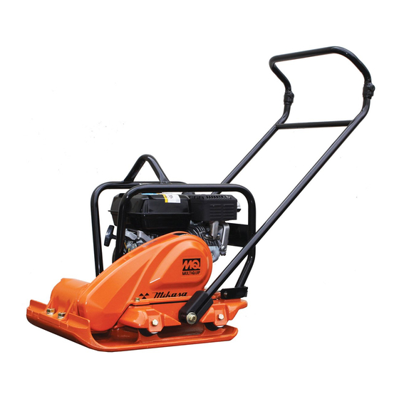
- Page 1 OperatiOn and parts Manual SERIES MODEL MVC88VTH MODEL MVC88VTHW ONE-WAY pLATE COMpACTOR (HONDA GX160UT2QMX2 GASOLINE ENGINE) Revision #2 (12/09/13) THIS MANUAL MUST ACCOMPANY THE EQUIPMENT AT ALL TIMES.
-
Page 2: Proposition 65 Warning
pROpOSITION 65 WARNING page 2 — MVC88VTH/VTHW pLaTe COMpaCTOR • OpeRaTiOn and paRTs ManuaL — ReV. #2 (12/09/13) - Page 3 NOTES MVC88VTH/VTHW pLaTe COMpaCTOR • OpeRaTiOn and paRTs ManuaL — ReV. #2 (12/09/13) — page 3...
- Page 4 TAbLE Of CONTENTS MVC88VTH/MVC88VTHW Honda GX160UTQMX2 Engine Component Drawings forward plate Compactor Cylinder Head Assembly ........42-43 Proposition 65 Warning ........... 2 Cylinder Barrel Assembly ......... 44-45 Table Of Contents ............ 4 Crankcase Cover Assembly ......46-47 Parts Ordering Procedures ........5 Crankshaft Assembly ........
-
Page 5: Safety Information
SAfETY INfORMATION Do not operate or service the equipment before reading Potential hazards associated with the operation of this the entire manual. Safety precautions should be followed equipment will be referenced with hazard symbols which at all times when operating this equipment. may appear throughout this manual in conjunction with Failure to read and understand the safety safety messages. -
Page 6: Safety Information
„ neVeR use accessories or attachments that are not „ neVeR operate this equipment when not recommended by Multiquip for this equipment. Damage feeling well due to fatigue, illness or when to the equipment and/or injury to user may result. - Page 7 SAfETY INfORMATION COMpaCTOR saFeTy WaRning dangeR „ dO nOT place hands or fingers inside engine compartment when engine is running. „ neVeR operate the equipment in an explosive atmosphere or near combustible materials. An „ neVeR operate the engine with heat shields or explosion or fi re could result causing severe guards removed.
- Page 8 SAfETY INfORMATION FueL saFeTy baTTeRy saFeTy (eLeCTRiC sTaRT OnLy) dangeR dangeR „ dO nOT add fuel to equipment if it is placed inside truck „ dO nOT drop the battery. There is a possibility that the bed with plastic liner. Possibility exists of explosion or battery will explode.
- Page 9 SAfETY INfORMATION TRanspORTing saFeTy „ When the life cycle of this equipment is over, remove battery and bring to appropriate facility for lead CauTiOn reclamation. Use safety precautions when handling batteries that contain sulfuric acid. „ NEVER allow any person or animal to stand underneath „...
-
Page 10: Specifications
SpECIfICATIONS Table 1. MVC88VTH/VTHW One-Way plate Compactor specifications Centrifugal Force 3,372 lbs. (1,530 kg) Vibration Frequency 6,000 vpm (60 Hz) Traveling Speed 82 ft/min (25 m/min) Plate Size (L x W) 19.7 x 20.7 in (.500 x .525 mm) Max. Area of Compaction (no extensions) 8,100 sq. -
Page 11: Dimensions
DIMENSIONS Figure 1. Dimensions Table 3. dimensions ReF. des in. (MM) 24.5 (622) 22.5 (571) 43.5 (1,105) 36.0 (914) 19.7 (500) page 12 — MVC88VTH/VTHW pLaTe COMpaCTOR • OpeRaTiOn and paRTs ManuaL — ReV. #2 (12/09/13) -
Page 12: General Information
GENERAL INfORMATION deFiniTiOn OF pLaTe COMpaCTOR FRequenCy/speed The Mikasa MVC88VTH/VTHW is a walk behind, plate The compactor's vibrating plate produces a vibration compactor designed for the compaction of sand, mixed soils frequency of 6,000 VPM (vibrations per minute). The and asphalt. This plate compactor is a powerful compacting... -
Page 13: Compactor Components
COMpACTOR COMpONENTS MVC88VTHW MVC88VTH Figure 2. Plate Compactor Components Figure 2 shows the location of the basic controls and 7. WaterTube-sprinkler (VTHW Only) – Supplies water components of the MVC88VTH/VTHW Plate Compactor. to the soil via a splash plate. The function of each control is described below: 8. -
Page 14: Compactor Components
COMpACTOR COMpONENTS Figure 3. Engine Controls and Components iniTiaL seRViCing 6. air Cleaner – Prevents dirt and other debris from The engine (Figure 3) must be checked for proper entering the fuel system. Remove wing-nut on top of lubrication and filled with fuel prior to operation. Refer to the air filter canister to gain access to filter element. -
Page 15: Inspection
INSpECTION before starting dangeR 1. Read all safety instructions at the beginning of manual. eXpLOsiVe FueL! 2. Clean the compactor, removing dirt and dust, Motor fuels are highly flammable and can particularly the engine cooling air inlet, carburetor and be dangerous if mishandled. dO nOT air cleaner. -
Page 16: Inspection
INSpECTION V-beLT V-belt Tension V-belt Cover Removal The V-belt tension is proper if the V-belt bends 10 to 15 mm (Figure 10) when depressed with finger at midway between To inspect the V-belt, remove the three bolts that secure the clutch and vibrator pulleys. the belt cover to the frame as shown in Figure 8. -
Page 17: Startup
STARTUp 3. Place the choke lever (Figure 14) in the “CLOsed” CauTiOn position if starting a cold engine. dO nOT attempt to operate the compactor until the Safety, General Information and Inspection sections of this manual have CHOKE LEVER been read and thoroughly understood. This section is intended to assist the operator with the initial start-up of the compactor. -
Page 18: Startup
STARTUp 9. If the sprinkling of water is required, place water valve in the On position. Figure 18. Water Valve (ON) Figure 16. Starter Grip 10. To begin compacting, place the throttle lever (Figure 19) in the “Run” position NOTICE dO nOT pull the starter rope all the way to the end dO nOT release the starter rope after pulling. -
Page 19: Operation
OpERATION OpeRaTiOn sTOpping THe engine CauTiOn normal shutdown aLWays follow all safety rules referenced 1. Move the throttle lever to the idle position (Figure 20) in the safety section of this manual before and run the engine for three minutes at low speed. operating compactor. -
Page 20: Operation/Maintenance
OpERATION/MAINTENANCE general Cleanliness MainTenanCe General maintenance practices are crucial to the Clean the compactor daily. Remove all dust and debris performance and longevity of your compactor. This buildup (mud, clay etc.). If the compactor is steam-cleaned, equipment requires routine cleaning, inspection and ensure that lubrication is accomplished aFTeR steam lubrication. -
Page 21: Maintenance
MAINTENANCE inspection and Maintenance service Tables To make sure your plate compactor is always in good working condition before using, carry out the maintenance inspection in accordance with Table 5 and Table 6. engine Maintenance Perform engine maintance as listed in Table 5. Table 5. -
Page 22: Maintenance
MAINTENANCE Machine inspection engine air Cleaner dangeR Perfom machine inspection as listed in Table 6. dO nOT use gasoline or low flash point Table 6. Machine inspection solvents for cleaning the air cleaner. The interval Check solution possibility exists of fire or explosion which Machine Clean if necessary. -
Page 23: Spark Plug
MAINTENANCE 3. Clean foam element in warm, soapy water or 3. Thread spark plug into cylinder hole by hand to prevent nonflammable solvent. Rinse and dry thoroughly. Dip cross-threading, then tighten securely. the element in clean engine oil and completely squeeze out the excess oil from the element before installing. - Page 24 MAINTENANCE spaRk aRResTeR CLeaning 4. Carefully remove carbon deposits from the spark arrester screen (Figure 28) with a wire brush. Clean the spark arrester every 6 months or 100 hours. WIRE 1. Remove the 4 mm screw (3) from the exhaust deflector, BRUSH then remove the deflector.
-
Page 25: Explanation Of Code In Remarks Column
A blank entry generally indicates that the item is not sold “not sold separately” — Indicates that an item cannot separately or is not sold by Multiquip. Other entries will be purchased as a separate item and is either part of an be clarifi ed in the “Remarks”... -
Page 26: Suggested Spare Parts
SUGGESTED SpARE pARTS MVC88VTH/MVC88VTWH pLaTe COMpaCTOR WiTH HOnda gX160uT2qMX2 gasOLine engine 1 to 5 units qty. description 3 ...070100332 ....V-BELT 5....0650140480 ..SPARK PLUG 1....28462ZH8003 ..ROPE, RECOIL STARTER 5....17210ZE1517 ..ELEMENT, AIR CLEANER 1....17620Z4H020 ..CAP, FUEL TANK 1....17672Z4H000 ..FUEL FILTER, FUEL TANK 4....939010230 ....SHOCK ABSORBER NOTICE Part numbers on this Suggested Spare Parts list may... - Page 27 bODY ASSY. (EG) 15 16 page 28 — MVC88VTH/VTHW pLaTe COMpaCTOR • OpeRaTiOn and paRTs ManuaL — ReV. #2 (12/09/13)
- Page 28 bODY ASSY. paRT nO. paRT naMe qTy. ReMaRks 416910120 HANDLE ASSY..........1....INCLUDES ITEMS W/% 416120141 VIBRATING PLATE 939010230 SHOCK ABSORBER 020310080 NUT M10 030210250 WASHER, LOCK M10 416120390 BASE 001221025 BOLT 10X25 030210250 WASHER, LOCK M10 416454360 RUBBER PLATE 25X25X8 912216015 ENGINE ASSY.,GX160UT2QMX2 001220850...
- Page 29 bODY ASSY. (CONTINUED) (EG) 15 16 page 30 — MVC88VTH/VTHW pLaTe COMpaCTOR • OpeRaTiOn and paRTs ManuaL — ReV. #2 (12/09/13)
- Page 30 bODY ASSY. (CONTINUED) paRT nO. paRT naMe qTy. ReMaRks 416218770 GRIP, VAS HANDLE 416459320 HANDLE NUT, VAS HANDLE 416459340 RUBBER, VAS HANDLE 009120407 SUNK HEAD BOLT 10X20 955010311 TACH/HOUR METER 001220510 BOLT 5X10 030205130 WASHER, LOCK M5 58151 WASHER, FLAT M5 959026822 RUBBER TUBE 955010310...
- Page 31 VIbRATOR ASSY. page 32 — MVC88VTH/VTHW pLaTe COMpaCTOR • OpeRaTiOn and paRTs ManuaL — ReV. #2 (12/09/13)
- Page 32 VIbRATOR ASSY. paRT nO. paRT naMe qTy. ReMaRks 953405270 PLUG 1/4X14 X13L 953405260 PACKING 1/4" 416218390 ECCENTRIC ROTATOR 040406211 BEARING 6211 416338909 CASE COVER (R) 416338919 CASE COVER (L) 416349930 BELT COVER GUARD 060203030 OIL SEAL 050101000 O-RING 014208020 BOLT 8X20 030208200 WASHER, LOCK M8 416464470...
- Page 33 TRANSpORT WHEEL ASSY. page 34 — MVC88VTH/VTHW pLaTe COMpaCTOR • OpeRaTiOn and paRTs ManuaL — ReV. #2 (12/09/13)
- Page 34 TRANSpORT WHEEL ASSY. paRT nO. paRT naMe qTy. ReMaRks 0105050616 BOLT 6X15 030206150 WASHER, LOCK M6 020106050 NUT M6 012010030 BOLT 10X30 030210250 WASHER, LOCK M10 416466680 SPACER, WHEEL 416352490 BRACKET, WHEEL 012210035 BOLT 10X35 031110160 WASHER, FLAT M10 032110180 CONICAL LOCK WASHER 020310080 NUT M10...
- Page 35 SpRINKLER ASSY. page 36 — MVC88VTH/VTHW pLaTe COMpaCTOR • OpeRaTiOn and paRTs ManuaL — ReV. #2 (12/09/13)
- Page 36 SpRINKLER ASSY. paRT nO. paRT naMe qTy. ReMaRks 416910110 WATER TANK W/CAP ........1 ....INCLUDES ITEMS W/% 033910050 WASHER 14.5X30X1.6 953406390 PACKING 13X28X2 954403241 COCK PT 1/4" 416338930 SPRINKLING PIPE 416338940 PIPE HOLDER (L) 416452750 PIPE HOLDER (R) 001220825 BOLT 8X25 0401450080 WASHER, FLAT M8 416452790...
- Page 37 URETHANE pLATE ASSY. page 38 — MVC88VTH/VTHW pLaTe COMpaCTOR • OpeRaTiOn and paRTs ManuaL — ReV. #2 (12/09/13)
- Page 38 URETHANE pLATE ASSY. paRT nO. paRT naMe qTy. ReMaRks 416352080 HANGER, URETHANE PLATE 001221230 BOLT 12X30 012012030 WASHER, LOCK M12 416352090 PLATE, URETHANE PLATE 011208035 BOLT 8X35 022710809 NYLON NUT M8 PADUPA88 PAD, URETHANE ..........1....REPLACES 416342390 MVC88VTH/VTHW pLaTe COMpaCTOR • OpeRaTiOn and paRTs ManuaL — ReV. #2 (12/09/13) — page 39...
-
Page 39: Nameplate And Decals
NAMEpLATE AND DECALS ASSY. page 40 — MVC88VTH/VTHW pLaTe COMpaCTOR • OpeRaTiOn and paRTs ManuaL — ReV. #2 (12/09/13) -
Page 40: Nameplate And Decals
NAMEpLATE AND DECALS ASSY. paRT nO. paRT naMe qTy. ReMaRks 920218170 DECAL, POSITION 920900090 DECAL, SET/MVC/EXP, EU ......1....SET ONLY 920101410 DECAL, MIKASA MARK 120X60 920105070 DECAL, MIKASA MARK 125MM 920217430 PLATE, SERIAL NO./88VTH 920217440 PLATE, SERIAL NO./88VTHW 920210330 DECAL, EC NOISE REQ.LWA105 920208350 DECAL, V-BELT RPF3330 920203290... - Page 41 HONDA GX160UT2QMX2 ENGINE — CYLINDER HEAD ASSY. page 42 — MVC88VTH/VTHW pLaTe COMpaCTOR • OpeRaTiOn and paRTs ManuaL — ReV. #2 (12/09/13)
- Page 42 HONDA GX160UT2QMX2 ENGINE — CYLINDER HEAD ASSY. paRT nO. paRT naMe qTy. ReMaRks 12204ZE1306 GUIDE, INLET VALVE (O.S.) 12205ZE1315 GUIDE, EXHAUST VALVE (O. S.) ......1....INCLUDES ITEMS W/$ 12210Z4M405 HEAD COMP, CYLINDER ........1....INCLUDES ITEMS W/% 12216ZE5300 CLIP, VALVE GUIDE 12251ZL0003 GASKET, CYLINDER HEAD 12310Z4M000 COVER CP, HEAD 12391ZE1000...
- Page 43 HONDA GX160UT2QMX2 ENGINE — CYL. bARREL ASSY. page 44 — MVC88VTH/VTHW pLaTe COMpaCTOR • OpeRaTiOn and paRTs ManuaL — ReV. #2 (12/09/13)
- Page 44 HONDA GX160UT2QMX2 ENGINE — CYL. bARREL ASSY. paRT nO. paRT naMe qTy. ReMaRks 12000Z4M406 BARREL, ASSY CYLINDER (OIL ALERT) ..1....INCLUDES ITEMS W/$ 16510Z4M000 GOVERNOR ASSY..........1....INCLUDES ITEMS W/% 16511Z4M000 WEIGHT, GOVERNOR 16512Z4M000 HOLDER, GOVERNOR WEIGHT 16513ZE1000 PIN, GOVERNOR WEIGHT 16531Z4M000 SLIDER, GOVERNOR 16541Z4M000 SHAFT, GOVERNOR ARM...
- Page 45 HONDA GX160UT2QMX2 ENGINE — CRANKCASE COVER ASSY. page 46 — MVC88VTH/VTHW pLaTe COMpaCTOR • OpeRaTiOn and paRTs ManuaL — ReV. #2 (12/09/13)
- Page 46 HONDA GX160UT2QMX2 ENGINE — CRANKCASE COVER ASSY. paRT nO. paRT naMe qTy. ReMaRks 11300Z4M640 COVER, ASSY. CRANKCASE ......1....INCLUDES ITEMS W/# 11381ZH8801 GASKET CRANKCASE 15600Z0T810 CAP ASSY. OIL FILLER ........1....INCLUDES ITEMS W/$ 15600Z0T820 CAP ASSY. OIL FILLER ........1....INCLUDES ITEMS W/% 15625Z0T800 PACKING, OIL FILLER CAP 91201Z0T801 OIL SEAL 25X41X6...
- Page 47 HONDA GX160UT2QMX2 ENGINE — CRANKSHAfT ASSY. page 48 — MVC88VTH/VTHW pLaTe COMpaCTOR • OpeRaTiOn and paRTs ManuaL — ReV. #2 (12/09/13)
- Page 48 HONDA GX160UT2QMX2 ENGINE — CRANKSHAfT ASSY. paRT nO. paRT naMe qTy. ReMaRks 13310Z4M800 CRANK SHAFT COMPLETE 90745ZE1600 KEY 4.78X4.78X38 MVC88VTH/VTHW pLaTe COMpaCTOR • OpeRaTiOn and paRTs ManuaL — ReV. #2 (12/09/13) — page 49...
- Page 49 HONDA GX160UT2QMX2 ENGINE — pISTON ASSY. page 50 — MVC88VTH/VTHW pLaTe COMpaCTOR • OpeRaTiOn and paRTs ManuaL — ReV. #2 (12/09/13)
- Page 50 HONDA GX160UT2QMX2 ENGINE — pISTON ASSY. paRT nO. paRT naMe qTy. ReMaRks 13010Z4M801 RING SET, PISTON (STD) 13101Z4M800 PISTON (STD) 13111Z4M000 PIN, PISTON 13200Z4M000 ROD AY, CONNECTING ........2....INCLUDES ITEMS W$ 90001Z4M000 BOLT, CONNECTING ROD 6X34.5 90551ZE1000 CLIP, PISTON PIN 18MM MVC88VTH/VTHW pLaTe COMpaCTOR •...
- Page 51 HONDA GX160UT2QMX2 ENGINE — CAMSHAfT ASSY. page 52 — MVC88VTH/VTHW pLaTe COMpaCTOR • OpeRaTiOn and paRTs ManuaL — ReV. #2 (12/09/13)
- Page 52 HONDA GX160UT2QMX2 ENGINE — CAMSHAfT ASSY. paRT nO. paRT naMe qTy. ReMaRks 12209Z4M801 SEAL, VALVE STEM 14100Z4M000 CAMSHAFT ASSY..........1....INCLUDES ITEM W/$ 14410Z4M000 ROD CP, PUSH 14431ZE1000 ARM, VALVE ROCKER 14441ZE1010 VALVE LIFTER 14451ZE1013 PIVOT, ROCKER ARM 14568ZE1000 SPRING, WEIGHT RETURN 14711Z4M000 VALVE, INTAKE 14721Z4M000...
- Page 53 HONDA GX160UT2QMX2 ENGINE — RECOIL STARTER ASSY. page 54 — MVC88VTH/VTHW pLaTe COMpaCTOR • OpeRaTiOn and paRTs ManuaL — ReV. #2 (12/09/13)
- Page 54 HONDA GX160UT2QMX2 ENGINE — RECOIL STARTER ASSY. paRT nO. paRT naMe qTy. ReMaRks 28400Z4M305ZD STARTER ASSY., RECOIL ........1....INCLUDES ITEMS W/$ 28410Z4M003ZD CASE CP, STARTER 28421Z0T003 REEL, RECOIL STARTER 28422ZH8801 RATCHET, STARTER 28431ZH8801 PLATE, FRICTION 28433ZH8801 RATCHET GUIDE 28441ZH8801 FRICTION SPRING 28442ZH8003 SPRING, RECOIL STARTER 28443ZH8801...
- Page 55 HONDA GX160UT2QMX2 ENGINE — fAN COVER ASSY. page 56 — MVC88VTH/VTHW pLaTe COMpaCTOR • OpeRaTiOn and paRTs ManuaL — ReV. #2 (12/09/13)
- Page 56 HONDA GX160UT2QMX2 ENGINE — fAN COVER ASSY. paRT nO. paRT naMe qTy. ReMaRks 19610Z4M000ZB COVER COMPLETE 19611Z4M810 PLATE CP, SIDE (OIL ALERT) 19630Z4M000 SHROUD COMPLETE 34150ZH7013 ALERT, UNIT, OIL 35120Z0T851 SWITCH AY, E/G STOP 90013883000 FLANGE BOLT 6X12 90022888010 FLANGE BOLT 6X20 90601ZH7013 CLIP, HARNESS 957010600800...
- Page 57 HONDA GX160UT2QMX2 ENGINE — CARbURETOR ASSY. page 58 — MVC88VTH/VTHW pLaTe COMpaCTOR • OpeRaTiOn and paRTs ManuaL — ReV. #2 (12/09/13)
- Page 58 HONDA GX160UT2QMX2 ENGINE — CARbURETOR ASSY. paRT nO. paRT naMe qTy. ReMaRks 1#@+&^ 16010ZE1812 GASKET SET 16011ZE0005 FLOAT VALVE SET 16013Z0SB01 FLOAT SET 16015Z4M911 CHAMBER SET, FLOAT ........1 ...INCLUDES ITEMS W/+ 16016ZH7W01 SCREW SET, PILOT 16024Z5T901 SCREW SET, DRAIN ........1 ...INCLUDES ITEMS W/^ 16028Z5T901 SCREW SET ..........1 ...INCLUDES ITEMS W/&...
- Page 59 HONDA GX160UT2QMX2 ENGINE — AIR CLEANER ASSY. page 60 — MVC88VTH/VTHW pLaTe COMpaCTOR • OpeRaTiOn and paRTs ManuaL — ReV. #2 (12/09/13)
- Page 60 HONDA GX160UT2QMX2 ENGINE — AIR CLEANER ASSY. paRT nO. paRT naMe qTy. ReMaRks 16271ZE1000 PACKING, ELBOW 17210ZE1517 CLEANER ELEMENT ........1....INCLUDES ITEMS W/# 17218ZE1507 OUTER ELEMENT 17231Z4M010 COVER, AIR CLEANER 17232891000 GROMET, AIR CLEANER 17235Z4M830 NOSE, SILENCER 17238ZE7010 COLLAR, AIR CLEANER 17239ZE1000 COLLAR (B), AIR CLEANER 17410Z4M000...
- Page 61 HONDA GX160UT2QMX2 ENGINE — MUffLER ASSY. page 62 — MVC88VTH/VTHW pLaTe COMpaCTOR • OpeRaTiOn and paRTs ManuaL — ReV. #2 (12/09/13)
- Page 62 HONDA GX160UT2QMX2 ENGINE — MUffLER ASSY. paRT nO. paRT naMe qTy. ReMaRks 18320Z4M000 PROTECTOR CP, MUFFLER (STD) 18340ZE1010 DEFLECTOR CP 18355ZE1000 ARRESTER, SPARK 18381Z0T801 GASKET, MUFFLER 18522ZE1000 GUIDE, MUFFLER 90002Z0T800 SCREW, TAPPING, 4X8 90016ZE1000 FLANGE BOLT 6X13 90050ZE1000 TAPPING SCREW 5X8 90055ZE1000 TAPPING SCREW 4X6 94001080000S...
- Page 63 HONDA GX160UT2QMX2 ENGINE — fUEL TANK ASSY. page 64 — MVC88VTH/VTHW pLaTe COMpaCTOR • OpeRaTiOn and paRTs ManuaL — ReV. #2 (12/09/13)
- Page 64 HONDA GX160UT2QMX2 ENGINE — fUEL TANK ASSY. paRT nO. paRT naMe qTy. ReMaRks 16854ZH8000 RUBBER, SUPPORT (107MM) 16955ZE1010 JOINT, FUEL TANK 17631Z0T801 PACKING, FUEL FILLER CAP 90004ZH7003 FLANGE BOLT 6X29 91353671004 O-RING 14MM 9405006000 FLANGE NUT 6MM 91424Z4M003 TUBE, FUEL 4.5X145 950024080008 CLAMP, TUBE (D8) 17620Z4H020...
- Page 65 HONDA GX160UT2QMX2 ENGINE — fLYWHEEL ASSY. page 66 — MVC88VTH/VTHW pLaTe COMpaCTOR • OpeRaTiOn and paRTs ManuaL — ReV. #2 (12/09/13)
- Page 66 HONDA GX160UT2QMX2 ENGINE — fLYWHEEL ASSY. paRT nO. paRT naMe qTy. ReMaRks 13331357000 WOODRUFF KEY 25X18 19511ZE1000 COOLING FAN 28451ZH8801 STARTER PULLEY 31110Z4M000 FLYWHEEL COMPLETE 90201Z0T800 NUT, SPECIAL 14MM MVC88VTH/VTHW pLaTe COMpaCTOR • OpeRaTiOn and paRTs ManuaL — ReV. #2 (12/09/13) — page 67...
- Page 67 HONDA GX160UT2QMX2 ENGINE — IGNITION COIL ASSY. page 68 — MVC88VTH/VTHW pLaTe COMpaCTOR • OpeRaTiOn and paRTs ManuaL — ReV. #2 (12/09/13)
- Page 68 HONDA GX160UT2QMX2 ENGINE — IGNITION COIL ASSY. paRT nO. paRT naMe qTy. ReMaRks 30500Z0T802 COIL ASSY, IGNITION 30700Z0T811 CAP ASSY, NOISE SUPPRESSOR 36101ZE1010 CORD, STOP SWITCH 370MM 90121952000 FLANGE BOLT 6X25 MVC88VTH/VTHW pLaTe COMpaCTOR • OpeRaTiOn and paRTs ManuaL — ReV. #2 (12/09/13) — page 69...
- Page 69 HONDA GX160UT2QMX2 ENGINE — CONTROL ASSY. page 70 — MVC88VTH/VTHW pLaTe COMpaCTOR • OpeRaTiOn and paRTs ManuaL — ReV. #2 (12/09/13)
- Page 70 HONDA GX160UT2QMX2 ENGINE — CONTROL ASSY. paRT nO. paRT naMe qTy. ReMaRks 16500Z4M306 CONTROL ASSY..........1....INCLUDES ITEMS W/# 16551Z4M000 ARM, GOVERNOR 16555Z4M000 ROD, GOVERNOR 16561Z4M010 SPRING GOVERNOR 16562Z4M000 SPRING, THROTTLE RETURN 16571Z4M000 LEVER, CONTROL 16574ZE1000 LEVER SPRING 16575ZH8000 WASHER, CONTROL LEVER 16576891000 HOLDER, CABLE 16578ZE1000...
-
Page 71: Decals
HONDA GX160UT2QMX2 ENGINE — DECALS page 72 — MVC88VTH/VTHW pLaTe COMpaCTOR • OpeRaTiOn and paRTs ManuaL — ReV. #2 (12/09/13) -
Page 72: Decals
HONDA GX160UT2QMX2 ENGINE — DECALS paRT nO. paRT naMe qTy. ReMaRks 87521Z4M000 EMBLEM (GX160) 87528Z4M000 MARK, CHOKE 87532ZH7000 MARK, THROTTLE INDICATION 87516Z4H010 MARK, OP CAUTION (ENGLISH) 87539Z4M000 MARK, EX. CAUTION (ENGLISH) 87516Z4H801 MARK, OP CAUTION (FR) 87519Z4H000 MARK, OP CAUTION 87539Z4M800 MARK. -
Page 73: Terms And Conditions Of Sale — Parts
Multiquip be $5.00. meeting this requirement. liable for loss of profi t or good will or for any Special order items. - Page 74 NOTES MVC88VTH/VTHW pLaTe COMpaCTOR • OpeRaTiOn and paRTs ManuaL — ReV. #2 (12/09/13) — page 75...
Need help?
Do you have a question about the Mikasa MVC88VTH and is the answer not in the manual?
Questions and answers