MULTIQUIP Mikasa Series Operation And Parts Manual
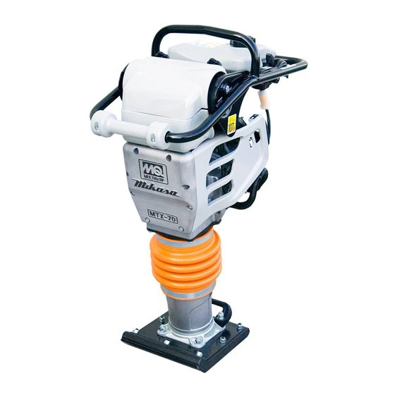
Tamping rammer. honda gx100ukrbf gasoline engine
Hide thumbs
Also See for Mikasa Series:
- Operation and parts manual (116 pages) ,
- Operation manual (90 pages) ,
- Manual (64 pages)
Table of Contents
Advertisement
Advertisement
Table of Contents

Related Manuals for MULTIQUIP Mikasa Series


Summary of Contents for MULTIQUIP Mikasa Series
- Page 1 OPERATION AND PARTS MANUAL SERIES MODEL MTX70 TAMPING RAMMER (HONDA GASOLINE ENGINE) GX100UKRBF Revision #13 (07/01/19) To find the latest revision of this publication, visit our website at: www.multiquip.com THIS MANUAL MUST ACCOMPANY THE EQUIPMENT AT ALL TIMES.
-
Page 2: Proposition 65 Warning
MTX70 — PROPOSITION 65 WARNING PAGE 2 — MTX70 — OPERATION AND PARTS MANUAL — REV. #13 (07/01/19) - Page 3 NOTES MTX70 — OPERATION AND PARTS MANUAL — REV. #13 (07/01/19) — PAGE 3...
-
Page 4: Table Of Contents
MTX70 — TABLE OF CONTENTS MTX70 Tamping Rammer HONDA GX100UKRBF Proposition 65 Warning ........... 2 ENGINE Table Of Contents ........... 4 Cylinder Barrel Assembly ........38-39 Parts Ordering Procedures ........5 Crankcase Cover Assembly ....... 40-41 Safety Information ..........6-9 Crankshaft Assembly ......... -
Page 5: Table Of Contents
, 2006 Order via Internet (Dealers Only) Best Deal! If you have an MQ Account, to obtain a Username Order parts on-line using Multiquip’s SmartEquip website! and Password, E-mail us at: parts@multiquip. com. View Parts Diagrams Order Parts To obtain an MQ Account, contact your District Sales Manager for more information. -
Page 6: Safety Information
MTX70 — SAFETY INFORMATION Do not operate or service the equipment before reading Potential hazards associated with the operation of this the entire manual. Safety precautions should be followed equipment will be referenced with hazard symbols which at all times when operating this equipment. may appear throughout this manual in conjunction with Failure to read and understand the safety safety messages. - Page 7 NEVER lubricate components or attempt service on a NEVER use accessories or attachments that are not running machine. recommended by Multiquip for this equipment. Damage NOTICE to the equipment and/or injury to user may result. ALWAYS keep the machine in proper running condition.
- Page 8 MTX70 — SAFETY INFORMATION ENGINE SAFETY FUEL SAFETY DANGER DANGER The engine fuel exhaust gases contain poisonous carbon DO NOT add fuel to equipment if it is placed inside truck monoxide. This gas is colorless and odorless, and can bed with plastic liner. Possibility exists of explosion or cause death if inhaled.
- Page 9 MTX70 — SAFETY INFORMATION TRANSPORTING SAFETY CAUTION NEVER allow any person or animal to stand underneath the equipment while lifting. NOTICE Before lifting, make sure that the equipment parts (hook and vibration insulator) are not damaged and screws are not loose or missing. Always make sure crane or lifting device has been properly secured to the lifting bail (hook) of the equipment.
-
Page 10: General Information
MTX70 — GENERAL INFORMATION Definition of Tamping Rammer CAUTION CAUTION CAUTION CAUTION CAUTION Handle Operation The Mikasa MTX70 tamping rammer is a powerful compacting tool capable of applying a tremendous force in consecutive impacts to a soil surface. Its applications include Before starting operation check the lifting soil compacting for road, embankments and reservoirs as handle to:... -
Page 11: Specifications
MTX70 — SPECIFICATIONS Table 1. MTX-70 Rammer Specifications Overall Height 39.37 in. (1000 mm Overall Width 13.78 in. (350 mm) Over Length 31.02 in (788 mm) Shoe Size (W x L) 13.4 x 11.2 (340 x 285 mm) Fuel Tank Capacity 3.2 qt. -
Page 12: Controls And Components
MTX70 — CONTROLS AND COMPONENTS Figure 1. MTX70 Rammer Figure 1 shows the location of the controls and components for the MTX70 Tamping Rammer. The functions of each control is described below: Combination (Throttle) Lever – Used to adjust engine 4. -
Page 13: Basic Engine
MTX70 — BASIC ENGINE Figure 1A. Engine Controls and Components (Honda GX100) INITIAL SERVICING The engine (Figure 1A) must be checked for proper lubrication and filled with fuel prior to operation. Refer to the manufacturers Engine manual for instructions & details of operation and servicing. Muffler –... - Page 14 MTX70 — OPERATION Engine This section is intended to assist the operator with the initial start-up of the MTX70 Tamping Rammer. It extremely 1. Fill the fuel tank (Figure 3) with unleaded gasoline. At the important that this section be read carefully before attempting same time, check the engine oil and make it a habit to to operate the rammer.
- Page 15 MTX70 — OPERATION Inspection DO NOT press the primer pump bulb more 1 . Check all nuts, bolts fasteners for tightness. Retighten as than four (4) times, as this will cause fuel necessary. to flood the carburetor. 2. Clean any dirt from the recoil starter and foot pedestal. Wipe the entire unit clean before operating.
-
Page 16: Operation
MTX70 — OPERATION Operation Stopping The Engine 1. To start the rammer tamping action, move the throttle lever Normal Shutdown (Figure 8) quickly from IDLE to the START ( ) position. 1. Move throttle lever quickly from the START to IDLE position DO NOT move the throttle lever slowly as this may cause (Figure 9) and run the engine for three minutes at low speed. -
Page 17: Maintenance
MTX70 — MAINTENANCE EVERY 200 HOURS Maintenance ■ Remove the oil drain plug on foot housing (Figure 13) and Perform the scheduled maintenance procedures as indicated: drain the oil. Refill with approximately 1.7 pt. (800 cc.) of DAILY 10W-30 SE, SF or higher grade motor oil. Oil should be ■... -
Page 18: Troubleshooting Guide
MTX70 — TROUBLESHOOTING GUIDE c i f t l u t r a i t i n i r b i t i n i s o o i t i c a l o i t i l i a l i w . - Page 19 MTX70 — TROUBLESHOOTING GUIDE ENGINE ENGINE ENGINE ENGINE ENGINE i t n i t a f s i e r r v e l . r e i r p v i t o i t o i t u l f l f l r r e i t a...
- Page 20 A blank entry generally indicates that the item is not sold assembly/kit that can be purchased, or is not available separately or is not sold by Multiquip. Other entries will for sale through Multiquip. be clarified in the “Remarks” Column.
-
Page 21: Suggested Spare Parts
MTX70— SUGGESTED SPARE PARTS MTX70 RAMMER 1 TO 3 UNITS WITH HONDA GX100UKRBF ENGINE Qty. Description 1 ..956100062 ..THROTTLE WIRE 3 ..366010070 ..SECONDARY ELEMENT, AIR CLEANER 3 ..366010080 ..PRIMARY ELEMENT, AIR CLEANER 1 ..366900020 ..CAP, FUEL TANK W/ STRAP 2 .. -
Page 22: Name Plate And Decals
MTX70— NAMEPLATE AND DECALS NAME PLATE AND DECALS NPA-0000 NPA-1245 NPA-0000 NPA-0000 MODEL SERI A L NO. A (DECAL SET) series RAMMER quick manual Engine Oil Use SAE 10W/30,SE or higher grade motor oil RAMMING CYLINDER OIL Use SAE 10W/30,SF or higher grade moter oil Fuel Use normal quality gasoline PAGE 22 —... - Page 23 MTX70— NAMEPLATE AND DECALS NAME PLATE AND DECALS PART NO PART NAME QTY. REMARKS 920900040 DECAL SET ........1..INCLUDES ITEMS W/ # DECAL: OPERATION DECAL: AIR CLEANER DECAL: LEVER OPERATION DECAL: MAX SPEED DECAL: MACHINE STOP DECAL: EC NOISE REQ DECAL: ANTI-VIB HANDLE 920212540 QUICK MANUAL...
- Page 24 MTX70 — CRANKCASE AND ENGINE ASSY. CRANKCASE AND ENGINE ASSY. 36-4 36-3 70-1 36-2 70-2 70-3 36-1 36-7 36-9 36-8 42-1 36-5 42-2 42-3 54-1 54-2 32-1 32-1 43-2 43-1 STYLE CLUTCH STYLE 57-2 25-2 CLUTCH 57-1 25-1 57-2 57-1 PAGE 24 —...
- Page 25 MTX70 — CRANKCASE AND ENGINE ASSY. CRANKCASE AND ENGINE ASSY. PART NO. PART NAME QTY. REMARKS 366910010 CRANK CASE ........1....INCLUDES ITEMS W/ $ 009120204 STUD BOLT 10 X 30 041006007 BEARING 6007Z 366345170 DRUM, PINION 060404010 OIL SEAL TC-40528 080200350 STOP RING S-35 080100620...
- Page 26 MTX70 — CRANKCASE AND ENGINE ASSY. CRANKCASE AND ENGINE ASSY. 36-4 36-3 70-1 36-2 70-2 70-3 36-1 36-7 36-9 36-8 42-1 36-5 42-2 42-3 54-1 54-2 32-1 32-1 43-2 43-1 STYLE CLUTCH STYLE 57-2 25-2 CLUTCH 57-1 25-1 57-2 57-1 PAGE 26 —...
- Page 27 MTX70 — CRANKCASE AND ENGINE ASSY. CRANKCASE AND ENGINE ASSY. PART NO. PART NAME QTY. REMARKS 42-1 001220851 BOLT 8X55 T 42-2 030208200 WASHER, LOCK M8 42-3 031108160 WASHER, FLAT M8 43-1 001210815 BOLT 8X15 43-2 030208200 WASHER, LOCK M8 366217340 COVER, CLEANER (UPPER) 366460140...
- Page 28 MTX70 — GUIDE CYLINDER AND SPRING ASSY. GUIDE CYLINDER AND FOOT ASSY. PAGE 28 — MTX70 — OPERATION AND PARTS MANUAL — REV. #13 (07/01/19)
- Page 29 MTX70 — GUIDE CYLINDER AND SPRING ASSY. GUIDE CYLINDER AND FOOT ASSY. PART NO. PART NAME QTY. REMARKS 366460100 PISTON PIN 366459910 PLUG, PISTON PIN0 366346000 PISTON ROD 371459690 PISTON END 001221230 BOLT 12X30 T 030212300 WASHER, LOCK M12 952404790 WASHER 13306 355447260 STOPPER, LOWER...
- Page 30 MTX70 — FOOT ASSY. FOOT ASSY. PAGE 30 — MTX70 — OPERATION AND PARTS MANUAL — REV. #13 (07/01/19)
- Page 31 MTX70 — FOOT ASSY. FOOT ASSY. PART NO. PART NAME QTY. REMARKS 366910020 FOOT ASSY 285 022711214 NYLON NUT M12 030212300 WASHER, LOCK M12 009110034 BOLT, SQUARE NECK 12X65 009110035 BOLT, SQUARE NECK 12X95 363343390 GRIP HANDLEBAR ON NUT M10 MTX70 —...
- Page 32 MTX70 — TANK AND HANDLE ASSY. TANK AND HANDLE ASSY. FOR CARBURETORS WITHOUT PRIMING BULBS FOR CARBURETORS WITH PRIMING BULBS 11-2 11-1 11-2 11-1 11-2 11-1 NOTES ITEM 110, PRIMER PUMP KIT, FOR USE ON UNITS WITH S/N T-3363 AND ABOVE PAGE 32 —...
- Page 33 MTX70 — TANK AND HANDLE ASSY. TANK AND HANDLE ASSY. PART NO. PART NAME QTY. REMARKS 366346270 SHOCK ABSORBER W/PIN 001521020 SOCKET HEAD BOLT 10 X 20 T 033121009 TOOTHED LOCK WASHER B M10 366119040 HANDLE / MTX70 001211020 BOLT 10 X 20 H 030210250 WASHER, LOCK M10 939010270...
- Page 34 MTX70 — COMBINATION LEVER ASSY. COMBINATION LEVER ASSY. PAGE 34 — MTX70 — OPERATION AND PARTS MANUAL — REV. #13 (07/01/19)
- Page 35 MTX70 — COMBINATION LEVER ASSY. COMBINATION LEVER ASSY. PART NO. PART NAME QTY. REMARKS 366900032 COMB. LEVER W/ THROTTLE WIRE ......1 ..INCLUDES ITEMS W/@ 956200110 COMB. LEVER W/OUT THROTTLE WIRE ....1 ..INCLUDES ITEMS W/ # 366346260 FUEL COCK, OLD STYLE ..........
-
Page 36: Tools
MTX70 — TOOLS TOOLS PAGE 36 — MTX70 — OPERATION AND PARTS MANUAL — REV. #13 (07/01/19) -
Page 37: Tools
MTX70 — TOOLS TOOLS PART NO. PART NAME QTY. REMARKS 981010400 CLUTCH PULLER A 983010060 CLUTCH MOUNTER 983910090 PISTON ROD HOLDER 009110044 SOCKET HEAD BOLT 8X50 (FULL THREAD) CRANK GEAR REMOVER 983910020 CLUTCH PULLER B 983010040 SPRING CYLINDER REMOVER 983910010 PISTON END REMOVER MTX70 —... - Page 38 HONDA GX100UKRBF ENGINE — CYLINDER BARREL ASSY. PAGE 38 — MTX70 — OPERATION AND PARTS MANUAL — REV. #13 (07/01/19)
- Page 39 HONDA GX100UKRBF ENGINE — CYLINDER BARREL ASSY. CYLINDER BARREL ASSY. PART NO. PART NAME QTY. REMARKS 12000Z0DV00 BARREL ASSY., CYLINDER ......1....INCLUDES ITEMS W/@ 12201Z0D305 GUIDE ASSY., EX VALVE (O.S.) 12204Z0D305 GUIDE, INLET VALVE (O.S) 12311Z0D000 COVER, HEAD T 12355Z0D000 COVER COMP A, BREATHER 12365Z0D000 COVER COMP B, BREATHER 15571Z0DV71...
- Page 40 HONDA GX100UKRBF ENGINE — CRANKCASE COVER ASSY. MTX70 — EH12-2D ROBIN ENGINE— CRANKSHAFT AND PISTON PAGE 40 — MTX70 — OPERATION AND PARTS MANUAL — REV. #13 (07/01/19)
- Page 41 HONDA GX100UKRBF ENGINE — CRANKCASE COVER ASSY. CRANKCASE COVER ASSY. PART NO. PART NAME QTY. REMARKS 11300Z0D409 COVER ASSY., CRANK CASE ......1....INCLUDES ITEMS W/@ — E— CRANKSHAFT AND PISTON 15600ZM7003 OIL FILLER CAP ASSY ........2....INCLUDES ITEMS W/# 15625ZE1003 PACKING, OIL FILLER CAP 16510ZL8000 GOVERNOR ASSY.
- Page 42 HONDA GX100UKRBF ENGINE — CRANKSHAFT ASSY. 85.3 PAGE 42 — MTX70 — OPERATION AND PARTS MANUAL — REV. #13 (07/01/19)
- Page 43 HONDA GX100UKRBF ENGINE — CRANKSHAFT ASSY. CRANKSHAFT ASSY. PART NO. PART NAME QTY. REMARKS 13310Z0DV70 CRANK SHAFT COMP........1....INCLUDES ITEM W/ @ 91001Z0DV01 BEARING, RADIAL BALL MTX70 — OPERATION AND PARTS MANUAL — REV. #13 (07/01/19) — PAGE 43...
-
Page 44: Piston Connecting Rod
HONDA GX100UKRBF ENGINE — PISTON CONNECTING ROD ASSY. PAGE 44 — MTX70 — OPERATION AND PARTS MANUAL — REV. #13 (07/01/19) -
Page 45: Piston Connecting Rod
HONDA GX100UKRBF ENGINE — PISTON CONNECTING ROD ASSY. PISTON CONNECTING ROD ASSY. PART NO. PART NAME QTY. REMARKS 13010Z0D003 RING SET, PISTON 13101Z0D000 PISTON 13111ZE0000 PISTON PIN 13200Z0D000 CONNECTING ROD ASSY. INCLUDES ITEM W/ @ 13200Z0D305 CONNECTING ROD ASSY. UNDERSIZE, INCLUDES ITEM W/ @ 90001ZM7000 CONNECTING ROD BOLT 90551ZE0000... - Page 46 HONDA GX100UKRBF ENGINE — CAMSHAFT ASSY. PAGE 46 — MTX70 — OPERATION AND PARTS MANUAL — REV. #13 (07/01/19)
- Page 47 HONDA GX100UKRBF ENGINE —CAMSHAFT ASSY. CAMSHAFT ASSY. PART NO. PART NAME QTY. REMARKS 14320Z0D010 PULLEY, COMP., CAMSHAFT 14324Z0D000 SHAFT, CAM PULLEY 14400Z0D003 TIMING BELT (61YU7 G-200) 14431Z0D000 ROCKER ARM, INTAKE VALVE 14441Z0D000 ROCKER ARM, EXHAUST VALVE 14461ZL8000 SHAFT, ROCKER ARM 14711Z0D000 INLET VALVE 14721Z0D000...
- Page 48 HONDA GX100UKRBF ENGINE — RECOIL STARTER ASSY. PAGE 48 — MTX70 — OPERATION AND PARTS MANUAL — REV. #13 (07/01/19)
- Page 49 HONDA GX100UKRBF ENGINE — RECOIL STARTER ASSY. RECOIL STARTER ASSY. PART NO. PART NAME QTY. REMARKS 28400Z0DV03ZA RECOIL STARTER ASSY ........1....INCLUDES ITEMS W/ @ 28410Z0DV02ZA CASE COMP., RECOIL @5-3-5 28421Z0DV02 REEL, RECOIL STARTER 28422ZG0W02 RATCHET, STARTER 28433ZG0W02 GUIDE, RATCHET 28441ZW6003 SPRING, FRICTION 28442ZH8003 SPRING, RECOIL STARTER...
- Page 50 HONDA GX100UKRBF ENGINE — FAN COVER ASSY. PAGE 50 — MTX70 — OPERATION AND PARTS MANUAL — REV. #13 (07/01/19)
- Page 51 HONDA GX100UKRBF ENGINE — FAN COVER ASSY. FAN COVER ASSY. PART NO. PART NAME QTY. REMARKS 19610Z0DV00ZB FAN COVER CP. 90014952000 BOLT, FLANGE 6X14 (CT200) MTX70 — OPERATION AND PARTS MANUAL — REV. #13 (07/01/19) — PAGE 51...
- Page 52 HONDA GX100UKRBF ENGINE — CARBURETOR ASSY. (S/N T-3362 AND BELOW) PAGE 52 — MTX70 — OPERATION AND PARTS MANUAL — REV. #13 (07/01/19)
-
Page 53: Carburetor Assy (S/N T-3362 And Below)
HONDA GX100UKRBF ENGINE — CARBURETOR ASSY. (S/N T-3362 AND BELOW) CARBURETOR ASSY. (S/N T-3362 AND BELOW) PART NO. PART NAME QTY. REMARKS 16010Z0DV02 GASKET, METALING DIAPHRAGM 16011Z0DV02 GASKET, PUMP 16013Z0DV02 DIAPHRAGM ASSY, METALING 16014Z0DV02 DIAPHRAGM, PUMP 16018ZM3004 SCREEN, INLET 16019ZM3004 VALVE, INLET NEEDLE 16022ZM3014 PIN, METALING LEVER... - Page 54 HONDA GX100UKRBF ENGINE — CARBURETOR ASSY. (S/N T-3363 AND ABOVE) PAGE 54 — MTX70 — OPERATION AND PARTS MANUAL — REV. #13 (07/01/19)
-
Page 55: Carburetor Assy (S/N T-3363 And Above)
HONDA GX100UKRBF ENGINE — CARBURETOR ASSY. (S/N T-3363 AND ABOVE) CARBURETOR ASSY. (S/N T-3363 AND ABOVE) PART NO. PART NAME QTY. REMARKS 16010Z0DV02 GASKET, METERING DIAPHRAGM 16011Z0DV02 GASKET, PUMP 16013Z4ES32 DIAPHRAGM ASSY, METERING 16014Z0DV02 DIAPHRAGM, PUMP 16018ZM3004 SCREEN, INLET 16019ZM3004 VALVE, INLET NEEDLE 16022ZM3014 PIN, METERING LEVER... - Page 56 HONDA GX100UKRBF ENGINE — AIR CLEANER ASSY. PAGE 56 — MTX70 — OPERATION AND PARTS MANUAL — REV. #13 (07/01/19)
- Page 57 HONDA GX100UKRBF ENGINE — AIR CLEANER ASSY. AIR CLEANER ASSY. PART NO. PART NAME QTY. REMARKS 17228Z0DV01 PACKING, AIR CLEANER 90042Z4ES30 STUD BOLT 5X95 9405005000 FLANGE NUT 5MM 17410Z4ES30 ELBOW, AIR CLEANER MTX70 — OPERATION AND PARTS MANUAL — REV. #13 (07/01/19) — PAGE 57...
- Page 58 HONDA GX100UKRBF ENGINE — MUFFLER ASSY. PAGE 58 — MTX70 — OPERATION AND PARTS MANUAL — REV. #13 (07/01/19)
- Page 59 HONDA GX100UKRBF ENGINE — MUFFLER ASSY. MUFFLER ASSY. PART NO. PART NAME QTY. REMARKS 18310Z0DV20 MUFFLER COMP. 18321Z0DV20 MUFFLER PROTECTOR 18381Z0D000 GASKET, MUFFLER 90014952000 VOLT, FLANGE 6X14 (CT200) 90048Z0DV00 STUD BOLT 5X78 90343ZE6000 NUT, SELF-LOCK 6MM MTX70 — OPERATION AND PARTS MANUAL — REV. #13 (07/01/19) — PAGE 59...
- Page 60 HONDA GX100UKRBF ENGINE — FLYWHEEL IGNITION ASSY. PAGE 60 — MTX70 — OPERATION AND PARTS MANUAL — REV. #13 (07/01/19)
- Page 61 HONDA GX100UKRBF ENGINE — FLYWHEEL IGNITION ASSY. FLYWHEEL IGNITION ASSY. PART NO. PART NAME QTY. REMARKS 13331ZM7000 WOODRUFF KEY 25X18 30564ZA5000 GROMMET, CORD 31110Z0D003 FLYWHEEL COMP. 90022888010 FLANGE BOLT 6X20 9405012000 FLANGE NUT M12 28451Z0DV02 STARTER PULLEY 30500Z0DV02 IGNITION COIL ASSY ........1....INCLUDES ITEMS W/ @ 30700Z0DV01 TERMINAL ASSY.
- Page 62 HONDA GX100UKRBF ENGINE — CONTROL ASSY. PAGE 62 — MTX70 — OPERATION AND PARTS MANUAL — REV. #13 (07/01/19)
- Page 63 HONDA GX100UKRBF ENGINE — CONTROL ASSY. CONTROL ASSY. PART NO. PART NAME QTY. REMARKS 16555Z0DV00 GOVERNOR ROD 16561Z0DV00 GOVERNOR SPRING 16562Z0DV00 SPRING, THROTTLE RETURN 16594883010 HOLDER, WIRE 90014952000 VOLT, FLANGE 6X14 (CT200) 90015ZE5010 BOLT, GOVERNOR ARM 90605230000 CIR CLIP 92301050200A BOLT 5X20 93500040060H SCREW 4X6...
- Page 64 HONDA GX100UKRBF ENGINE — LABELS ASSY. PAGE 64 — MTX70 — OPERATION AND PARTS MANUAL — REV. #13 (07/01/19)
- Page 65 HONDA GX100UKRBF ENGINE — LABELS ASSY. LABELS ASSY. PART NO. PART NAME QTY. REMARKS 87521Z0DV01 LABEL, TRADE MARK 87528Z0D000 MARK, CHOKE 87601Z4ES30 MARK, TYPE (KRBF) 89216130690 WRENCH, SPARK PLUG MTX70 — OPERATION AND PARTS MANUAL — REV. #13 (07/01/19) — PAGE 65...
-
Page 66: Terms And Condition Of Sale - Parts
Multiquip be $5.00. meeting this requirement. liable for loss of profit or good will or for any Special order items. - Page 67 NOTES MTX70 — OPERATION AND PARTS MANUAL — REV. #13 (07/01/19) — PAGE 67...
- Page 68 © COPYRIGHT 2019, MULTIQUIP INC. Multiquip Inc , the MQ logo are registered trademarks of Multiquip Inc. and may not be used, reproduced, or altered without written permission. All other trademarks are the property of their respective owners and used with permission.
Need help?
Do you have a question about the Mikasa Series and is the answer not in the manual?
Questions and answers