Table of Contents
Advertisement
Quick Links
Advertisement
Table of Contents

Related Manuals for BK Precision 1794


Summary of Contents for BK Precision 1794
- Page 1 B PRECISION Instruction Manual Model 1794 High Current Power Supply...
- Page 2 Limited Two Year Warranty B & K Precision Corp. warrants to the original purchaser that its product and the component parts therof, will be free from defects in workmanship and materials for a period of two years from the data of purchase. B &...
-
Page 3: Table Of Contents
TABLE OF CONTENTS SECTION PARTICULARS GENERAL INFORMATION SPECIFICATIONS INSTALLATION OPERATING INSTRUCTIONS SERVICE INSTRUCTIONS PART LIST SCHEMATICS CIRCUIT DIAGRAMS PAGE NO. -
Page 4: Limit Setting
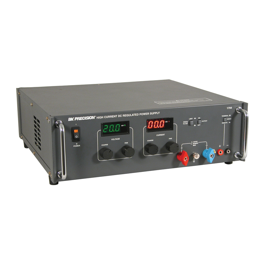
DESCRIPTION : The 1794 High Current Regulated D.C. Power Supply is completely solid and suitable for bench operation or standard 19" rack operation. It is a well regulated constant voltage / constant current supply which delivers 0-32V at 0-20Amps and can be adjusted continuously throughout the output range. -
Page 5: Section - 2 Specifications
OUTPUT VOLTAGE LOAD CURRENT CONSTANT VOLTAGE MODE REGULATION LINE LOAD RIPPLE & NOISE CONSTANT CURRENT MODE REGULATION LINE LOAD RIPPLE & NOISE OVERLOAD PROTECTION TRANSIENT RESPONSE STABILITY : Total drift within 8 hours,after warm up under constant line, load & temp. PANEL METERS MODE INDICATION SET LIMIT/ ON-OFF... -
Page 6: Section - 3 Installation
INITIAL INSPECTION : As soon as the power supply 1794 unit is unpacked, inspect for any damage that may have occurred during transit. Save all packing material until inspection is completed. If any damage is found, notify the carriers immediately. Our authorised representatives should also be notified. -
Page 7: Repackaging For Shipment
230V Mains Operation at the Input of EMI Filter located at bottom side of the unit. REPACKAGING FOR SHIPMENT : To ensure safe shipment of the power supply 1794 unit, it is recommended that the package designed for the unit be used. The original packaging material is reusable. -
Page 8: Section - 4 Operating Instructions
Press OUTPUT switch to ON position and observe that CV LED lights ( CONSTANT CURRENT VOLTAGE (CC) MODE : a. Turn off the suppy. Short circuit the output terminals of the power supply & turn on the supply. b. Keep the OUTPUT ON/OFF switch in the OFF position ( c. -
Page 9: Remote Sensing
Remote sensing is accomplished by connnecting the load to remote sense terminals on the front panel. The leads from the sensing( +S and -S) terminals to the load will carry much less current than the load leads and it is not required that these leads be as heavy as the load leads. -
Page 10: Output Capacitance
OUTPUT CAPACITANCE : Internal capacitor C3 ( L1791-FP-CNT-0603 PCB ) connected across the output terminals of the power supply, helps to supply high current pulses of short duration during constant voltage operation. Any capacitance added externally will improve the pulse current capability, but will decrease the safety provided by the constant current circuit. - Page 11 OPERATORS SAFETY SUMMARY The general safety information in this part of the summary is for both operating & servicing personnel. Specific warnings and cautions will be found throughout the manual where they apply, but may not appear in this summary. TERMS IN THIS MANUAL : CAUTION : Statements identify conditions or practices that could result in...
-
Page 12: Servicing Safety Summary
USE THE PROPER FUSE : To avoid fire hazard, use only fuse of the correct type, voltage rating and current rating as specified in the parts list for your product. For 115V operation 20A, For 230V operation 10A Slow blow. Refer fuse replacement to qualified service personnel. -
Page 13: Troubleshooting Techniques
GENERAL : The instrument has been tested throughly and then released for dispatch.Normally, the unit works satisfactorily under all condition. However due to ageing / misuse or malfunctioning, the unit may become defective. In case, the user wants to carryout Servicing, the following instructions will be helpful in rectifying the defects. -
Page 14: Repairs & Maintenance
checked by substituting a new component for it ( or one which has been checked previously). However, be replacement transistor might also be damaged. If substitute transistors are not available, use a dynamic tester. Static-type testers are not recommended, since they do not check operation under simulated operating conditions. - Page 15 5.3.6 If Fuse blows, connect the unit through a variable AC Source with a current meter and monitor the current at no load. If the current is very high (more than 2 ampere or so ) load, check for Bridge Rectifier short or shorted Diode, or Secondary Winding short, etc 5.3.7 If output voltage or current DPM's are not reading, check for loose connections especially in crimping, soldering, of Connectors.
- Page 16 5.4.3 VOLTAGES AT VARIOUS PINS OF IC LM324 IS AS FOLLOWS ( IC-101 ) :- IC PIN NO. VOLTAGES & CHECK CONDITIONS PIN1 0V ( WHEN V POT KEPT AT MIN. POSITION IN CV MODE ) PIN1 +5V ( WHEN V POT KEPT AT MAX. POSITION IN CV MODE ) PIN2 &...
-
Page 17: Circuit Boards
5.5.2 ORDERING PROCEDURE : When ordering replacement parts from B+K Inc. please include the following minimum information : Power Supply Type ( 1794 ). Power Supply Serial Number ( For example, 03080001 ). A description of the part ( if electrical include the circuit number ). - Page 18 Static discharge can damage any semiconductor This instrument contains electrical components that are susceptible to damage from static discharge. Static voltages of 1KV to 30KV are common in unprotected environments. Observe the following precautions to avoid damage : Minimize handling of static-sensitive components. Transport and store static-sensitive components or assemblies in their original containers, on a metal rail, or on conductive foam.
-
Page 19: Fault Finding Procedure
FAULT FINDING PROCEDURE ( A ) FUSE BLOWS FUSE BLOWS Is Line Voltage OK ? Is Fuse Rating OK ? Is Mains Transformer Tapping OK ? Are Power Diodes Connected on Heat Sink Short ? Is Remote Sense Switch Pressed in Normal Condition ? Is Device Drop setting proper on Load ? Turn ON the Unit at Rated input Voltage. - Page 20 ( B ) UNREGULATED O/P VOLTAGE UNREGULATED O/P VOLTAGE Is IC LM324 OK ? Is Voltage Pot Open OR Pot Wire is Reaching PCB ? Are Mosfets OK ? Is Gate Wire of Mosfet Reaching PCB ? Are Diodes D3 and D4 on Front Panel PCB OK ? Is INT &...
- Page 21 ( C ) NO OUTPUT VOLTAGE. NO O/P VOLTAGE Is IC LM324 OK ? Is Voltage Pot Short ? Is Voltage Selection Preset Open ? Are Zener Diodes Z1 & Z2, Preset VR1 on Preg. PCB OK ? Are all the Auxillary Winding Reaching PCB ? Is there proper contact of Load Terminal with Terminal Nuts...
- Page 22 ( D ) NO DPM INDICATION. NO DPM INDICATION Is Display Completely Blank ? Does Display shows only dot Indication ? Is Continuity between IC7905 & DPM's OK ? Is Continuity between ANGD & DPM's OK ? Is DPM IC OK ? Replace It.
- Page 23 Check DPM IC 7107. It might be Damaged. Check minimum Output Voltage of Potemtiometer. It should be less than 150mV. See that Power Supply is earthed properly. Check IC TL 431 ( Z1 and Z2 ) on Front Panel PCB. It might be Damaged.
-
Page 24: Schematics
( F ) UNIT NOT TAKE CURRENT. UNIT NOT TAKE CURRENT Is Current Set Preset R21 OK ? Is Current Pot Short ? Is Wiring Related to Current Pot OK ? Are Load Terminals connected properly with Nut inside Unit ? Ensure proper Terminal Contact. - Page 25 ( G ) UNIT DIRECTLY GOES TO CC. UNIT DIRECTLY GOES TO CC Is Shunt Resistor open OR Dry Soldered ? Is IC LM324 OK ? Is Current select Preset R21 Open ? Is Remote Sense Terminal Pressed ? Ensure Remote Sense Switch is Unpressed in Normal Condition.
- Page 26 ( H ) NO CURRENT CONTROL. NO CURRENT CONTROL Is Current Pot Open ? Are Wires related to Current Pot OK ? Ensure proper Connectivity. Check the Current Potentiometer. It might be Open. Check all Wires related to Current Potentiometer. ( I ) POOR LINE REGULATION.
- Page 27 ( J ) POOR LOAD REGULATION. POOR LOAD REGULATION Load Terminal Nut inside Unit might be Loose. Is there any Oscillation in CV Mode ? Is Capacitor C4 and C2 Leaky ? Replace It. Load Terminal might be Loose. Ensure Terminals are tightened properly with Terminal Nuts inside the Unit.
- Page 28 ( L ) EXTERNAL PROGRAMMING NOT OK. EXTERNAL PROGRAMMING NOT OK Is Pot connected across INT & COM OK ? Is there proper Continuity between PROG Terminal and O/P +Ve ? Ensure proper Connectivity. Check whether 5K Pot is connected between INT and COM Terminal. Check whether there is proper Continuity between PROG Terminal and Output Positive.
-
Page 29: Section - 6 Part List & Schematics
L1791-FP-CNT-0603 PCB ASSY Reference Part Designator Description RESISTORS Not Used 100E 3.3K 2.2K 1K, 10W 3.3E 100E 500E(3206F) ZENERS TL 431 DIODES 1N4148 1N4148 1N4148 CAPACITORS 1KPF/100V, DISC 1µF/100V, ELE 220µF/50V, ELE 1KPF/100V, DISC LM324 SWITCHES SW1-3 2P2W SW PUSH BUTTON TERMINALS 60A / 1000V O/P +Ve RED TERMINAL 60A / 1000V O/P -Ve LIGHT BLUE TERMINAL... - Page 30 L1791-FP-CNT-0603 PCB ASSY Reference Part Designator Description CONNECTORS J2.54 - 3MSL, 3 PIN SIL 2.54mm ST LOCK MALE J2.54 - 3FSL, 3 PIN SIL 2.54mm ST LOCK FEMALE CLAMPS SINGLE PUSH SWITCH MTG. CLAMP DOUBLE PUSH SWITCH MTG. CLAMP DOUBLE PUSH SWITCH MTG. CLAMP SWITCHES GREY COLOUR CAP FOR PUSH SWITCH GREY COLOUR CAP FOR PUSH SWITCH...
-
Page 31: Circuit Diagrams
PS-PREG-1791-0503 PCB ASSLY Reference Part Designator Description TRANSISTORS BC 109 MPSA12 BC 557 ZENERS 4.7V, ½W PRESET 5K ( 3206F ) HOR TRANSFORMER EE25 PULSE TX. Z-DPM/01 REV - 01 X 2 Reference Part Designator Description RESISTORS 39K, 0.25W, 5%, MFR 470K, 0.25W, 5%, MFR R7 1M, 0.25W, 5%, MFR SEL ( INPUT ) - Page 32 PS-AUX-DC-L1791-0503 PCB ASSLY Reference Part Designator Description CAPACITORS 470µF/35V, ELE 47µF/35V, ELE 10µF/35V, ELE 10µF/35V, ELE 100nF/50V, DISC C12 Not Used Not Used LM 78T12 LM 7905 BRIDGE W06M, 600V, 3A DIODES 1N4007 1N4007 1N4007 CONNECTORS J2.54ST/10, 10PIN SIL 2.54mm ST LOCK MALE J2.54ST/10, 10PIN SIL 2.54mm ST LOCK FEMALE J2.54ST/12, 12PIN SIL 2.54mm ST LOCK MALE J2.54ST/12, 12PIN SIL 2.54mm ST LOCK FEMALE...
- Page 33 FRONT PANEL ASSLY Reference Part Designator Description 5K, WWPOT 1K, WWPOT SWITCH 16A/250V ON/OFF SWITCH 7. MAIN CHASSIS ASSLY Reference Part Designator Description RESISTOR 4.7K/2W, MOR 0.025E / 25W SHUNT DIODES U30D40C (30AMP/400V DUAL DIODE) CAPACITORS 6 X 15,000µF, ELE 1µF / 250V AC CAP X 2 RECTIFIER HEATSINK ASSLY DIODES...
- Page 37 BOTTOM VIEW OF MODEL : 1790 / 1791...
- Page 38 FRONT PANEL CONTROL PCB OF 1790 / 1791...
- Page 39 POWER MODULE PCB OF 1790 / 1791...
- Page 40 PRE REGULATOR / AUX. P/S PCBs 1790 / 1791...
- Page 41 Service Information Warranty Service : Please return the product in the original packaging with proof of purchase to the below address. Clearly state in writing the perfor- mance problem and return any leads, connectors and accessories that you are using with the device. Non-Warranty Service : Please return the product in the priginal packag- ing to the below address.
- Page 42 B PRECISION SN: 480-808-9-001 Printed in India (M-00198) B & K PRECISION CORP. 22820 Savi Ranch Parkway Yorba Linda, CA 92887 www.bkprecision.com...
Need help?
Do you have a question about the 1794 and is the answer not in the manual?
Questions and answers