
Related Manuals for BK Precision 1785B


Summary of Contents for BK Precision 1785B
- Page 1 Instruction Manual Version: November 3, 2010 Model 1785B, 1786B, 1787B & 1788 Programmable DC Power Supplies...
-
Page 2: Table Of Contents
4.4 Communication protocol ....................... 24 Chapter 5 PV1785B-1788 Software ......................30 5.1 Introduction ............................. 30 5.2 System Installation......................... 30 5.3 Functions of PV-1785B-1788 ....................... 30 5.3.1Configure the system ......................32 5.3.2 Status bar ..........................32 5.3.3 Setting Voltage and current ....................33 5.3.4. -
Page 3: Quick Reference
Quick Reference About your safety Pease review the following safety precautions before operating our equipment. General information The following safety precautions should be observed before using this product and any associated instrumentations. Although some instruments and accessories would be used with non-hazardous voltages, there are situations where hazardous conditions may be present. -
Page 4: Certification And Warranty
We certify that this product met its published specifications at time of shipment from the factory. Introduction The 1785B - 1788 Series power supplies are high performance single-output programmable DC power supplies with communication interface. The combination of bench-top and system features in these power supplies provides versatile solutions for your design and test requirements. -
Page 5: The Front Panel At A Glance
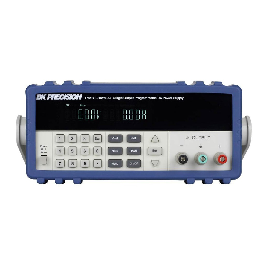
The Front Panel at a Glance ① 10 digits VFD display ② Status information for operating mode and working status ③ Power switch ④ Number keys ⑤ Function keys ⑥ UP/DOWN and ENTER key ⑦ Output terminals Function keys description Set the output voltage value V-set Set the current value... -
Page 6: Menu Description
Menu description Menu >MAX VOLT Set the maximum output voltage value >INIT OUT Initiate the output state to ON or not >INIT VOL Initiate the output voltage to 0 volt or not >KEY SOUN Switch On/Off the buzzer sound when you press any key >BAUD Set the communication baud rate... -
Page 7: The Rear Panel At A Glance
The Rear Panel at a Glance ① Cooling window ② DB9 interface connector ③ 110V/220V selector ④ Fuse ⑤ Power socket Chapter 1 Quick Start One of the first things you will want to do with your power supply is to become acquainted with the front panel. -
Page 8: Preliminary Checkout
some of its front-panel operations. This chapter is intended for both the experienced and the inexperienced user because it calls attention to certain checks that should be made prior to operation. 1.1 Preliminary Checkout The following steps help you verify that the power supply is ready for use. 1.Check the list of supplied items. -
Page 9: Current Output Checkout
2. Enable the outputs. Press key to let the annunciator and the annunciator turn on to light. Out on/off Notice: if the voltage value flash, then the power supply is in Set mode, ‘‘Set mode’’ means that the VFD display shows the setting output voltage and current. Or the power supply is in Meter mode, ‘Meter mode”... -
Page 10: To Adjust The Carrying Handle
3. Verify that the correct power-line fuse is installed. If the fuse was damaged, please see the table below to replace the fuse for your power supply. Model Fuse Description 1785B, Fuse 2.5A T 250V for 220VAC 1786B, Fuse 5A T 250V for 110VAC... - Page 11 Note: Remove the carrying handle and the two plastic ears before rack-mounting the instrument. To remove the handle, grasp the handle by sides and pull outwards and rotate it to a special position to let the arrow on the handle and the arrow on the plastic ears be in opposite directions, then pull the handle outward.
- Page 12 unit (mm) Dimension...
-
Page 13: Chapter 2 Specifications
Chapter 2 Specifications 2.1 Specifications Parameter 1785B 1786B 1787B 1788 0 ~18 0 ~32 0 ~72 0 ~32 Voltage Output Ratings, 0~1.5 ( 0 °C - 40 °C) Current 0 ~5 A 0 ~3 A 0~6 A 0 ~19 0 ~33... -
Page 14: Supplemental Characteristics
Environmental Conditions Designed for indoor use in an installation category II, pollution degree 2 environment. Designed to operate at maximum relative humidity of 95% and at altitudes of up to 2000 meters. Weight Type 1785B 1786B 1787B 1788 12.3Lbs. 14.8Lbs. - Page 15 (Unit: mm)
-
Page 16: Chapter 3 Front-Panel Operation
Chapter 3 Front-panel Operation So far you have learned how to install your power supply and do quick start. During the quick start, you were briefly introduced to operating from the front panel as you learned how to check basic voltage and current functions. -
Page 17: Constant Current Operation
Step1. Power on the Power Supply ▲ ▼ Step2. Press the keys to change the value Solution 2: Step1. Power on the instrument V-Set Step2. Press key. ▲ ▼ Step3. Use the numeric keys keys to change the voltage value. Step4. - Page 18 supply. Menu Step1. Press key. ▲ ▼ Step2. Select >MAX VOLT by using key. Step3. Press key. Enter ▲ ▼ Step4. Change the voltage value by using numeric keys key. Step5. Press key. Enter Note: After you setting the maximum voltage value, the output voltage setup should be in the range from 0 volt to maximum voltage.
- Page 19 Note: Default baud rate is 4800. Setting Address (>ADDRESS) This instruction can set the communication address for each power supply. The address range is from 0 to 30. Before the communication, you must make sure that there is same address between the power supply and the computer.
-
Page 20: Chapter 4 Remote Operation Mode
Chapter 4 Remote Operation Mode The DB9 interface connector on the rear panel of the power supply can be transferred to RS-232 interface, the following information will tell you how to use the computer to control the output of the power supply. -
Page 21: Frame Format
4.3 Frame format Packet structure The power supply is programmed using packets of bytes. A packet always contains 26 bytes, either going to or coming from the instrument. The basic programming rule is: You send a 26 byte packet to the instrument. You then read a 26 byte packet back from the power supply to either •... -
Page 22: Status Packets
Status packets When you send a command that does not cause the power supply to send requested information back to you, you will receive a status packet back. The structure of a status packet is Byte 0 Byte 1 Byte 2 Byte 3 Byte 4 to 24 Byte 25... - Page 23 Note: You must change the power supply to remote control mode first, then you can control the power supply output by computer. The command for remote control is 0x20. If you want to calibrate the power supply, set the calibration information. If you want to set the product serial number, you must set the calibration protection mode to OFF state first.
-
Page 24: Communication Protocol
4.4 Communication protocol 1.Setting the remote control mode (0x20) byte Start bit( 0xAA ) byte Address(0x00~0xFE) Command (0x20) byte byte Operation mode(0 represent front panel operation mode, 1 represent remote operation mode) to 25 byte System reserve byte Check sum Note: You cannot control the power supply from the front panel when the power supply is in calibration mode. - Page 25 4. Setting the output voltage (0x23) byte Start bit (0xAA ) byte Address(0x00~0xFE) byte Command(0x23) byte The byte 0 of output voltage value byte The byte 1 of output voltage value byte The higher byte of output voltage value byte The highest byte of output voltage value to 25 byte...
- Page 26 byte Byte 3 of present output voltage byte Power supply’s state byte To set the low byte of current value byte To set the high byte of current value byte Byte 0 of the maximum voltage value byte Byte 1 of the maximum voltage value byte Byte 2 of the maximum voltage value byte...
- Page 27 Note: We use a byte to represent calibration protection state,each bit is defined as follows: from higher bit to lower bit 0 bit:Protection state, 0 is to disable protection, 1 is to enable the protection. 9. Reading the calibration state (0x28) byte Start bit(0xAA) byte...
- Page 28 12. Calibrate the current value (0x2B) byte Start bit(0xAA) byte Address(0x00-0xFE) byte Command(0x2B) byte Calibrated current points( point 1-2) to 25 byte System reserve byte Check sum Note: To calibrate the 2 points of the current value sequentially. 13. Sending the actual output current to calibration program (0x2C) byte Start bit (0xAA) byte...
- Page 29 System reserve byte Check sum Note: For example, the serial number is 000045,the product model is 1785B,and software version is V2.03, then the returned data is as follows: 18. Restore the factory default calibration data (0x32) byte Start bit (0xAA)
-
Page 30: Chapter 5 Pv1785B-1788 Software
Windows 98/2000/XP or Windows NT4.0 2. Insert the CD-Rom which supplied with the instrument to the CD driver, and install the software step by step according to the instructions. 5.3 Functions of PV-1785B-1788 Start the software PV1785B-1788, the windows is as follows:... - Page 31 Configure the software operation environments. Voltage chart, it can show you a chart of the voltage. Current chart: it can show you a chart of the current. To set the remote mode of power supply. To set the output state ON/OFF To enable the local numeric key ⑦,it means that if you select “Enable”...
-
Page 32: 1Configure The System
5.3.1Configure the system The first step for communication is to configure the system, click Configure button , the windows will display as follows: 1) Comm: to set the communication port, baud rate and address. 2) Max voltage: to set a maximum voltage value in the voltage range. -
Page 33: Setting Voltage And Current
5.3.3 Setting Voltage and current 1. Setting voltage/current by rotary knob Use mouse to click on the rotary knob and move mouse to change the value. You also can use mouse wheel, or Page Up/Down keys and arrow keys (↑, ↓, ←, →) from the keyboard to change the voltage value more slightly. - Page 34 Voltage Sweep: To set voltage sweep. For example, StartValue=1V, Stop Value=12V, Voltage Step=0.5V, TimeDelay=2s. When you click the “Run” button, the voltage will change according to the voltage sweep setup value, display as follows: then you can click “Stop” button to stop the voltage sweep. 3.
-
Page 35: Go/Ng Test Function
5.3.4. GO/NG Test Function GO/NG is an auto test function, to test if the EUT (equipment under test) can meet the specification. To use this function, follow up the steps below: 1. Right-click on the window, the edit tools (Append a line, Insert a line, Delete a line, Delete Select etc.) will appear on the window. -
Page 36: Chart Description
5.3.7 Chart Description The voltage and current chart can help you to analyze voltage and current changes more easily. We take the voltage chart as the example to let you know how to use it. The chart window is as follows: Click here and Click here and move to zoom... -
Page 37: Service Information
SERVICE INFORMATION Warranty Service: Please go the support and service section on our website www.bkprecision.com to obtain a RMA #. Return the product in the original packaging with proof of purchase to the address below. Clearly state on the RMA the performance problem and return any leads, probes, connectors and accessories that you are using with the device. - Page 38 22820 Savi Ranch Parkway Yorba Linda, CA 92887 www.bkprecision.com © 2008-2010 B&K Precision Corp. Printed in China v110310...
Need help?
Do you have a question about the 1785B and is the answer not in the manual?
Questions and answers