
Related Manuals for BK Precision 1743B


Summary of Contents for BK Precision 1743B
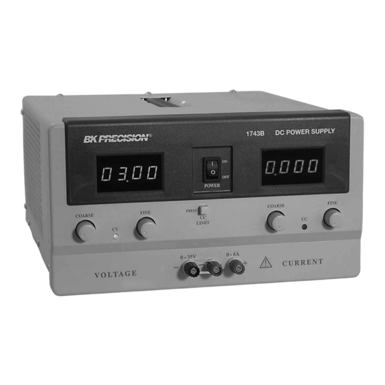
- Page 1 INSTRUCTION MANUAL Model 1743B MANUAL DE INSTRUCCIONES Modelo 1743B 0-35 V, 0-6 A DC POWER SUPPLY With Dual 4-Digit LED Displays Fuente de Poder de DC con Doble LED indicador ...
-
Page 2: Test Instrument Safety
TEST INSTRUMENT SAFETY WARNING Normal use of test equipment exposes you to a certain amount of danger from electrical shock because testing must sometimes be performed where exposed high voltage is present. An electrical shock causing 10 milliamps of current to pass through the heart will stop most human heartbeats. -
Page 3: Table Of Contents
Fuse Replacement --------------------------------------------- 22 Line Voltage Conversion ------------------------------------- 22 OPERATING INSTRUCTIONS -------------------------------- 10 Adjustments ---------------------------------------------------- 22 Safety Precautions ---------------------------------------------- 10 1743B Calibration --------------------------------------------- 23 Equipment Precautions ---------------------------------------- 10 Instrument Repair Service ------------------------------------ 23 Hook-Up --------------------------------------------------------- 10 Typical Constant Voltage Operation ------------------------- 13... -
Page 4: Introduction
INTRODUCTION The B+K Precision Model 1743B DC Power Supply is a high Current limits are adjustable from 5% to 100% of maximum. quality, general purpose dc power source. It provides 0-35 volts In constant current applications, the maximum voltage may dc output, adjustable with both coarse and fine voltage controls be preset. -
Page 5: Features
FEATURES 0-35 VOLTS LED INDICATORS Act as pilot light and identify mode of operation and metering. Continuously variable over 0-to-30 volt range with coarse and fine controls. PRE-REGULATOR 0-6 AMPS Limits internal dissipation for higher reliability. 0-to-6 amps current rated for continuous duty at full output current. -
Page 6: Specifications
SPECIFICATIONS OUTPUT VOLTAGE: 0 to 35 VDC, coarse and fine Line (108-132 V): ≤0.4% + 5 mA adjustment. Load ≤0.4% + 5 mA OUTPUT CURRENT: coarse fine Current Ripple: ≤3 mA typical. adjustment. METERING CONSTANT VOLTAGE OPERATION Voltmeter 4 digit Green LED Display Voltage Regulation Range: 0 to 99.99 V. - Page 7 SPECIFICATIONS TEMPERATURE RANGE WEIGHT: 24 lb. (10.4g) Operation: 0° to +40° C, ≤75% R.H. Storage: -15° to +70° C,≤ 85% R.H. ACCESSORIES SUPPLIED: Instruction Manual, Spare Fuse DIMENSIONS (HxWxD): 5.7” x 10.5” x 15” (145 x 267 x 38 NOTE: Specifications and information are subject to change without notice. Please visit www.bkprecision.com for the most current product information.
-
Page 8: Controls And Indicators
CONTROLS AND INDICATORS INDICATORS CURRENT CONTROL Either the “CC” or “CV” and the LED indicators will be lit 7. Coarse CURRENT Control. Adjusts current limit in whenever the unit is operating, thus serving as a pilot light. The unit constant voltage mode. - Page 9 CONTROLS AND INDICATORS REAR PANEL CONTROLS 7. Fuse. 8. Power Cord. 9. 110/220 Line Voltage Conversion Switch. Figure 1. Front Panel Controls and Indicators. Figure 2. Rear Panel...
-
Page 10: Operating Instructions
OPERATING INSTRUCTIONS SAFETY PRECAUTIONS Do not exceed the voltage rating of the circuit being powered. Most transistors and integrated circuits will not Use only a polarized 3-wire ac outlet. This assures that the power withstand voltage of 35 volts. supply chassis, case, and ground terminal are connected to a good earth ground and reduces danger from electrical shock. - Page 11 OPERATING INSTRUCTIONS Figure 3 (A and B). Grounding Possibilities.
- Page 12 OPERATING INSTRUCTIONS Figure 3 (C and D). Grounding Possibilities. ...
-
Page 13: Typical Constant Voltage Operation
OPERATING INSTRUCTIONS c. If an earth ground reference is not required, the configuration of Fig. 3Bmay be used. The scheme in Fig. 3C should also be used where it is not known whether the chassis is common with either the positive or negative polarity. -
Page 14: Setting Current Limit
OPERATING INSTRUCTIONS 5. . Increase the VOLTAGE setting until the Voltage LED display reads the desired value. The FINE control permits easier setting to a specific value. 7. Note the load current on the Current LED display. 8. If the load current exceeds the preset current limit, the CV indicator will go off and the CC indicator will light. -
Page 15: Typical Constant Current Operation
OPERATING INSTRUCTIONS TYPICAL CONSTANT CURRENT OPERATION 1. Before connecting the device to be powered to the power supply, determine the maximum safe voltage to be applied, and set the VOLTAGE controls to obtain that voltage reading on the Voltage LED display. 2. -
Page 16: Constant Voltage/Constant Current Characteristic
070 volt output. In this mode automatically occurs from a decrease in load. A good example of configuration, two 1743B’s provide up to 6 amps. See Fig. 8 this would be seen when charging a 12-volt battery. Initially, the open for the connection scheme. - Page 17 OPERATING INSTRUCTIONS Figure 8. Connecting Two Power Supplies in Series.
- Page 18 OPERATING INSTRUCTIONS Figure 9. Connecting Two Power Supplies in Parallel.
-
Page 19: Connecting Two Power Supplies In Parallel
OPERATING INSTRUCTIONS CONNECTING TWO POWER SUPPLIES IN PARALLEL If the current equalizing resistors are not well matched, it is preferable that the voltages be slightly unbalanced to achieve Two power supplies may be connected in parallel to double the current balance. -
Page 20: Applications
GENERAL The equipment being tested may contain its own power The Model 1743B power supply has a very wide variety of supply and operate from ac power. A dc voltage may already applications in electrical and electronics servicing, engineering be present in the circuit. -
Page 21: Electronics Design Lab
APPLICATIONS ELECTRONICS DESIGN LAB BATTERY CHARGING The technician or engineer working in an engineering laboratory The power supply can be used as a battery charger to requires a dc power supply to power breadboard and prototype restore the charge in rechargeable batteries such as lead-acid, circuits. -
Page 22: Maintenance
MAINTENANCE WARNING LINE VOLTAGE CONVERSION, INTERNATIONAL UNITS The following instructions are for use by qualified personnel only. To avoid electrical shock, do not perform any servicing other than The primary winding of the power transformer is tapped to contained in the operating instructions unless you are qualified to do permit operation from 120/220/230 or 240 VAC, 50/60 Hz line voltage. -
Page 23: 1743B Calibration
MAINTENANCE 1743BA CALIBRATION 1. Set the front panel Coarse VOLTAGE control for a If readjustment is required, use the following procedure. Locations reading of 04.00 to 06.00 volts on the GREEN of the adjustments are shown in Fig. - Page 24 MAINTENANCE Figure 11. Location of Adjustments.
-
Page 25: Warranty Service Instructions
Service Information Warranty Service: Please return the product in the original packaging with proof of purchase to the address below. -
Page 26: Limited Two-Year Warranty
Limited Two-Year Warranty B&K Precision Corp. warrants to the original purchaser that its products and the component parts thereof, will be free from defects in workmanship and materials for a period of two years from date of purchase. ... - Page 27 TEST INSTRUMENT SAFETY (continued from inside front cover) 4. I f possible, familiarize yourself with the equipment being tested and the location of its high voltage points. However, remember that high voltage may appear at unexpected points in defective equipment. 5.
- Page 28 22820 Savi Ranch Parkway Yorba Linda, CA 92887 www.bkprecision.com © 2002 B&K Precision Corp. V072814 Printed in Taiwan ...
Need help?
Do you have a question about the 1743B and is the answer not in the manual?
Questions and answers