Table of Contents
Advertisement
Quick Links
Advertisement
Table of Contents

Related Manuals for BK Precision 1739


Summary of Contents for BK Precision 1739
- Page 1 DC Power Supply with 0.1mA Settable Model 1739 Resolution INSTRUCTION MANUAL...
-
Page 3: Safety Summary
Safety Summary The following safety precautions apply to both operating and maintenance personnel and must be observed during all phases of operation, service, and repair of this instrument. Before applying power, follow the installation instructions and become familiar with the operating instructions for this instrument. - Page 4 WARNING and CAUTION statements, such as the following examples, denote a WARNINGS AND CAUTIONS hazard and appear throughout this manual. Follow all instructions contained in these statements. A WARNING statement calls attention to an operating procedure, practice, or condition, which, if not followed correctly, could result in injury or death to personnel.
- Page 5 Compliance Statements Disposal of Old Electrical & Electronic Equipment (Applicable in the European Union and other European countries with separate collection systems) This product is subject to Directive 2002/96/EC of the European Parliament and the Council of the European Union on waste electrical and electronic equipment (WEEE), and in jurisdictions adopting that Directive, is marked as being put on the market after August 13, 2005, and should not be disposed of as...
-
Page 6: Table Of Contents
Contents Safety Summary ............. 1 Introduction ..............5 Quick Reference ............. 7 Front Panel ..................7 Rear Panel ..................8 Operating Instructions ..........9 Instrument Hook-Up ................ 10 Typical Constant Voltage Operation ..........12 Setting Current Limit ............... 13 Typical Constant Current Operation ..........14 Constant Voltage/Constant Current Characteristic ...... -
Page 7: Introduction
Introduction Description The B&K Precision model 1739 is a high quality, low current DC power source. This power supply provides 0-30 volts dc output, adjustable with both coarse and fine voltage controls for precise settability. The current output is 0-1 amps, adjustable with both coarse and fine current controls. - Page 8 Reverse polarity protection prevents accidental damage to the power supply from improper connection to an external device, and current limiting protects the equipment being powered, as well as the power supply. The output is isolated from chassis and earth ground, which permits full flexibility of connections.
-
Page 9: Quick Reference
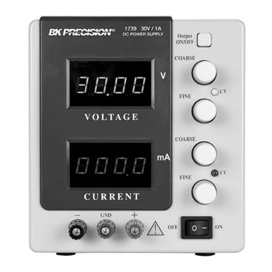
Quick Reference 3.1 Front Panel Figure 1 - Front Panel INDICATORS Either the CV or CC LED indicators will be lit whenever the unit is operating. The unit automatically changes from CV to CC operation when the preset current limit is reached. -
Page 10: Rear Panel
CURRENT CONTROL 7) Current Coarse Control. Adjusts current limit in constant voltage mode. Adjusts constant current value in constant current mode. Current can be read from the red LED display. 8) Current Fine Control. Adjusts current limit in constant voltage mode. Adjusts constant current value in constant current mode. -
Page 11: Operating Instructions
Operating Instructions Safety Precautions Use only a polarized 3-wire AC outlet. This assures that the power supply chassis, case, and ground terminal are connected to a good earth ground and reduces danger from electrical shock. There is little danger of electrical shock from the power supply output, which produces a maximum of 30 volts dc. -
Page 12: Instrument Hook-Up
4.1 Instrument Hook-Up 1. Turn off the power supply and the equipment to be powered during hook- 2. Connect the positive polarity of the device being powered to the red (+) terminal of the power supply. 3. Connect the negative polarity of the device being powered to the black (-) terminal of the power supply. - Page 13 Figure 3 (A and B) - Grounding Possibilities Figure 3 (C and D) - Grounding Possibilities...
-
Page 14: Typical Constant Voltage Operation
4.2 Typical Constant Voltage Operation 1. Before connecting the device to be powered to the power supply, determine the maximum safe load current for the device to be powered and set the current limit value (see Setting Current Limit procedure in this section). 2. -
Page 15: Setting Current Limit
4.3 Setting Current Limit 1. Determine the maximum safe current for the device to be powered. 2. Temporarily short the (+) and (-) terminals of the power supply together with a test lead. 3. Adjust the coarse and fine current control for the desired current limit. Read the current value on the current LED display. -
Page 16: Typical Constant Current Operation
4.4 Typical Constant Current Operation Before connecting the device to be powered to the power supply, determine the maximum safe voltage to be applied, and set the voltage controls to obtain that voltage reading on the voltage LED display. Determine the desired constant current value. Set the coarse and fine current control to minimum (1mA). -
Page 17: Constant Voltage/Constant Current Characteristic
4.5 Constant Voltage/Constant Current Characteristic The working characteristic of this power supply is called a constant voltage/constant current automatic crossover type. This permits continuous transition from constant current to constant voltage modes in response to the load change. The intersection Figure of constant voltage and constant current modes is called the crossover point. -
Page 18: Saving The Power Supply's Current State
4.6 Saving the Power Supply’s Current State The current state of the power supply is saved after 2 seconds from the last adjustment or after the “SAVE” command is received through the RS232 interface. 4.7 Connecting Two Power Supplies in Series Two power supplies may be connected in series to provide a variable 0-60 volt output. -
Page 19: Connecting Two Power Supplies In Parallel
4.8 Connecting Two Power Supplies in Parallel Two power supplies may be connected in parallel to double the maximum load current. In this configuration, the two power supplies will provide 0-30 volt output at up to 2 amps. Current equalizing resistors must be used as shown in Figure 9 . -
Page 20: Rs232 Interface
The power supply can be connected to the RS232 interface using the 9-pin (DB-9) serial connector on the rear panel. The 1739 uses a null modem RS232 cable. The cable pin diagram for the DB-9 connector is shown in the picture below:... -
Page 21: Rs232 Configuration Overview
5.1 RS232 Configuration Overview Baud Rate 9600 bps Parity Bits none Data Bits Start Bits Stop Bits Flow Control Xon / Xoff Termination Character CR (0x13) Table 1 - RS232 Configuration 5.2 RS232 Commands Note : All commands are case sensitive, therefore be sure all letters are CAPITALIZED before sending it to the instrument. - Page 22 CV<CR> if the power supply is in Constant Voltage mode CC<CR> if the power supply is in Constant Current mode 6. OUT ON<CR> Turn output power on. 7. OUT OFF<CR> Turn output power off. 8. IDN?<CR> The power supply responds with: “B+K PRECISION 1739 Revision x.x <CR>”.
-
Page 23: Maintenance
Maintenance WARNING The following instructions are for use by qualified personnel only. To avoid electrical shock, do not perform any servicing other than contained in the operating instructions unless you are qualified to do so. 6.1 Fuse Replacement If the fuse blows, the CV or CC indicators will not light and the power supply will not operate. -
Page 24: Calibration
6.3 Calibration Calibration is a procedure that ensures that the power supply will work properly, with parameters specified within the Specifications section. Before initiating the calibration procedure, the following conditions must be assured: • Disconnect any loads connected to the power supply and turn it on •... - Page 25 0 Low current calibration F Full current calibration The voltage coarse and fine and current fine knobs are not used. Important note! In order to perform a correct calibration procedure, you must select the full voltage calibration option just after the zero voltage calibration option, and the full current calibration option just after the low current calibration option.
- Page 26 3. Full voltage calibration To finish the voltage calibration procedure, the full voltage calibration must be done after the zero voltage calibration. a) Select “U F” for full voltage calibration and turn the voltage coarse knob. The power supply will display: Voltage display: Current display: hex number A hexadecimal number between 0 and FFFFh will be shown on the current...
- Page 27 b) Connect a digital ammeter (B&K Precision 5491B or similar instrument) to the output terminals of the power supply to initiate the zero current calibration procedure. If a digital ammeter is not connected within 30 seconds, the power supply will abandon the current calibration procedure and return to the Calibration menu.
- Page 28 Connect a digital ammeter (BK Precision 5491B or similar instrument) to the output terminals of the power supply to initiate the full current calibration procedure. If a digital ammeter is not connected within 30 seconds, the power supply will abandon the current calibration procedure and will return to the Calibration menu.
-
Page 29: Instrument Repair Service
6.4 Instrument Repair Service Because of the specialized skills and test equipment required for instrument repair and calibration, many customers prefer to rely upon B&K Precision for this service. We maintain a network of B&K Precision authorized service agencies for this purpose. - Page 30 Er 20: CC not high Er 21: CV not low Er 22: DAC out of range Er 23: ADC out of range Er 24: ADC system calibration failed Er 25: DAC zero voltage constant checksum failed Er 26: ADC zero voltage constant checksum failed Full voltage calibration errors: Er 30: CC not high Er 31: CV not low...
-
Page 31: Command Errors
“Syntax Error<CR>” : invalid syntax was found in the command string “Out of range<CR>” : a numeric parameter value is outside the valid range for the command Specifications 1739 Output Ratings ( 0 °C~40 °C) 0-30 V Voltage 0-999.9 mA Current Load Regulation ±(% of output+offset) - Page 32 NOTE: All specifications apply to the unit after a temperature stabilization time of 30 minutes. Specifications and information are subject to change without notice. To ensure the most current version of this manual, please download the current version here: http://www.bkprecision.com/search/manual/1739 For current up-to-date product information, please visit www.bkprecision.com...
-
Page 33: Service Information
Service Information Warranty Service: Please go to the support and service section on our website at www.bkprecision.com to obtain an RMA #. Return the product in the original packaging with proof of purchase to the address below. Clearly state on the RMA the performance problem and return any leads, probes, connectors, and accessories that you are using with the device. -
Page 34: Limited Three-Year Warranty
10 Limited Three-Year Warranty B&K Precision Corp. warrants to the original purchaser that its products and the component parts thereof will be free from defects in workmanship and materials, for a period of three years from date of purchase. B&K Precision Corp. will, without charge, repair or replace, at its option, defective product or component parts. - Page 35 (Page intentionally left blank)
- Page 36 22820 Savi Ranch Parkway Yorba Linda, CA 92887 www.bkprecision.com © 2012 B&K Precision Corp. Printed in Taiwan v071312...
Need help?
Do you have a question about the 1739 and is the answer not in the manual?
Questions and answers