Table of Contents
Advertisement
Quick Links
Advertisement
Table of Contents

Related Manuals for Pentair FLECK 9000 SXT


Summary of Contents for Pentair FLECK 9000 SXT
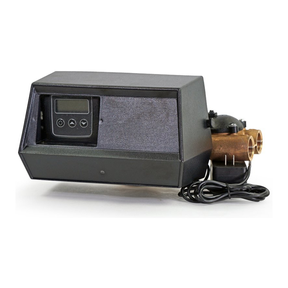
- Page 1 FLECK 9000 SXT INSTALLER MANUAL WATER PURIFICATION...
-
Page 2: Table Of Contents
Installer manual Fleck 9000 SXT - Table of Contents Table of Contents Generalities ..................Scope of the documentation ............... Release management ................. Manufacturer identifier, product ..............Intended use ....................Abbreviations used ..................Norms......................1.6.1 Applicable norms ....................1.6.2 Available certificates................... - Page 3 Installer manual Fleck 9000 SXT - Table of Contents 4.2.1 Parameters to be considered ................4.2.2 Determining the required volume of resin ............4.2.3 Resin exchange capacity and capacity of the unit ..........4.2.4 Valve configuration....................4.2.5 Cycle time calculation ..................
- Page 4 Installer manual Fleck 9000 SXT - Table of Contents 6.5.3 Display format mode (DF) ................... 6.5.4 Regeneration flow (VT) ..................6.5.5 Regeneration control type (CT) ................6.5.6 Number of tanks (NT)..................6.5.7 Tank in service (TS) ..................... 6.5.8 Unit capacity (C)....................
- Page 5 Installer manual Fleck 9000 SXT - Table of Contents 9.1.3 Regeneration test....................Recommended maintenance plan .............. 72 9.2.1 Valve used for softening..................Recommendations ..................74 9.3.1 Use original spare parts..................9.3.2 Use original approved lubricants................ 9.3.3 Maintenance instructions ................... Cleaning and maintenance................74 9.4.1...
- Page 6 Installer manual Fleck 9000 SXT - Table of Contents 11.12 Other components list................. 115 Disposal................... 117 6 / 118 Ref. MKT-IM-020 / C - 21.11.2019...
-
Page 7: Generalities
Installer manual Fleck 9000 SXT - Generalities Generalities Scope of the documentation The documentation provides the necessary information for appropriate use of the product. It informs the user to ensure efficient execution of the installation, operation or maintenance procedures. The content of this document is based on the information available at the time of publication. The original version of the document was written in English. -
Page 8: Intended Use
Installer manual Fleck 9000 SXT - Generalities Intended use The device is intended for commercial applications use only and it is purpose-built for water treatment. Abbreviations used Assy Assembly BLFC Brine Line Flow Controller Brine Valve Cold Water Down Flow... -
Page 9: Available Certificates
Installer manual Fleck 9000 SXT - Generalities Meets the following technical standards: • EN 55014-1; • EN 55014-2; • EN 61000-6-1; • EN 61000-6-2; • EN 61000-6-3; • EN 61000-6-4; • EN 61010-1; • EN 61000-3-2; • EN 61000-3-3. 1.6.2 Available certificates •... -
Page 10: Limitation Of Liability
Pentair Quality System EMEA products benefit, under specific conditions, from a manufacturer warranty that may be invoked by Pentair’s direct customers. Users should contact the vendor of this product for applicable conditions and in case of a potential warranty claim. -
Page 11: Scan & Service Application
Installer manual Fleck 9000 SXT - Generalities 1.10 Scan & Service application Scan & Service mobile application is the ideal support for the maintenance person in his daily business. A simple scan of an identification (ID) label (1) present on the valve with a smartphone gives an instantaneously access to all updated information related to the product, such as: •... -
Page 12: Safety
Installer manual Fleck 9000 SXT - Safety Safety Safety pictograms definition DANGER This combination of symbol and keyword indicates an imminently hazardous situation that will result in serious or fatal injury if not avoided. WARNING This combination of symbol and keyword indicates a potentially hazardous situation that can result in serious or fatal injury if not avoided. -
Page 13: Serial Label Location
Installer manual Fleck 9000 SXT - Safety Serial label location Model Part number Electrical rating Serial number Production date Production order Mandatory Ensure that the serial label and the safety labels on the device are completely legible and clean ! If necessary, replace them with new labels in the same positions. -
Page 14: Material
Installer manual Fleck 9000 SXT - Safety 2.3.2 Material The following points must be observed to ensure proper operation of the system and the safety of user: • be careful of high voltages present on the transformer (100 – 240 V);... -
Page 15: Description
Installer manual Fleck 9000 SXT - Description Description Technical specifications Design specifications/ratings Valve body Brass Rubber components EP or EPDM Valve material certification DM174, ACS ¾" 1" Weight (valve with controller) 8.6 kg 0.4 kg Recommended operating pressure 1.8 - 8.6 bar Maximum inlet pressure 8.6 bar... - Page 16 Installer manual Fleck 9000 SXT - Description Controller input voltage 24 VAC Controller max. power consumption Protection rating. IP 22 Power supply 100 to 240 VAC, 50/60 Hz, 0.5 A, Class II Transient overvoltages within the limits of category II Pollution Degree Temporary overvoltages must be limited in duration and in frequency.
-
Page 17: Performance Flow Rate Characteristics
Installer manual Fleck 9000 SXT - Description Performance flow rate characteristics The graph shows the pressure drop created by the valve itself at different flow rates. It allows predetermining the maximum flow rate going through the valve depending on the system settings (inlet pressure etc). -
Page 18: Downflow
Installer manual Fleck 9000 SXT - Description 3.3.1 Downflow Tank 1 in Service Tank 2 in Standby Tank 1 in Backwash Tank 2 in Tank Refill Tank 2 in Service Tank 1 in Service Tank 1 in Brine draw/slow Tank 2 in Fast Rinse... -
Page 19: Upflow
Installer manual Fleck 9000 SXT - Description 3.3.2 Upflow Tank 1 in Service Tank 2 in Standby Tank 1 in Brine draw/slow Tank 2 in Tank Refill rinse Tank 1 in Service Tank 2 in Service Tank 1 in Backwash... -
Page 20: Outline Drawing
Installer manual Fleck 9000 SXT - Description Outline drawing 20 / 118 Ref. MKT-IM-020 / C - 21.11.2019... -
Page 21: Components Description And Location
Installer manual Fleck 9000 SXT - Description Components description and location Controller LCD screen Regen button Up button Down button Camshaft Micro-switches Motor Second tank adapter Flexible tube Drain line Brine line Injector block Meter Inlet Outlet Ref. MKT-IM-020 / C - 21.11.2019... -
Page 22: System Regeneration Cycle
Installer manual Fleck 9000 SXT - Description System regeneration cycle Info This valve allows to do down flow or up flow regenerations. 3.6.1 Downflow regeneration cycle (5-cycles operation) Service — normal use Untreated water is directed down through the resin bed and up through the riser tube. The hardness ions attach themselves to the resin and are removed from the raw water being exchanged on the resin beads by sodium ions. - Page 23 Installer manual Fleck 9000 SXT - Description SERVICE NORMAL USE BACKWASH Outlet Inlet Outlet Inlet Drain Valve Valve BRINE DRAW & SLOW RINSE RAPID RINSE Outlet Inlet Outlet Inlet Drain Drain Valve Valve From brine tank SERVICE BRINE TANK REFILL...
-
Page 24: Upflow Regeneration Cycle (5-Cycles Operation)
Installer manual Fleck 9000 SXT - Description 3.6.2 Upflow regeneration cycle (5-cycles operation) Service — normal use Untreated water is directed down through the resin bed and up through the riser tube. The hardness ions attach themselves to the resin and are removed from the raw water being exchanged on the resin beads against sodium ions. - Page 25 Installer manual Fleck 9000 SXT - Description SERVICE NORMAL USE BRINE DRAW & SLOW RINSE Outlet Inlet Outlet Inlet Drain Valve Valve From brine tank BACKWASH RAPID RINSE Outlet Inlet Outlet Inlet Drain Drain Valve Valve SERVICE BRINE REFILL NORMAL USE...
-
Page 26: System Sizing
Installer manual Fleck 9000 SXT - System sizing System sizing Recommended Injector/DLFC/BLFC-Valve configuration Brine Tank Connect. Resin Injector DLFC BLFC syst. Diam flexible volume eter [in] [mm] Color Color [gpm] DF [gpm] UF [gpm] 9000/ 5 - 7 0.25 0.25... -
Page 27: Determining The Required Volume Of Resin
Installer manual Fleck 9000 SXT - System sizing Depending on the inlet water hardness, the service velocity for standard softening must be between: Service velocity Inlet water hardness °f °dH [bed volume per hour] [mg/l as CaCO °TH 8 - 40 <350... -
Page 28: Resin Exchange Capacity And Capacity Of The Unit
Installer manual Fleck 9000 SXT - System sizing = Fs × BV with: service max service : service flow rate [m service max : service velocity [BV/h] service BV: bed volume of resin [m Knowing this required volume of resin, it is possible now to determine the needed tank. Note that at least a third of the total volume of the tank must be kept as free space so that the bed expansion during backwash is sufficient to ensure correct cleaning of the resin. -
Page 29: Valve Configuration
Installer manual Fleck 9000 SXT - System sizing Salt amount Corresponding resin °f.m °dH.m [g/L exchange capacity in [g/L [per L [per L resin resin resin resin as CaCO 53.8 5.38 3.01 55.5 5.55 58.5 5.85 3.27 62.7 6.27 66.9 6.69... -
Page 30: Cycle Time Calculation
Installer manual Fleck 9000 SXT - System sizing regeneration of the unit. From this data, determine the required backwash flow rate as well as the brine draw and slow rinse flow rate. In most cases, the fast rinse flow rate will be the same as the backwash flow rate, however for certain valve types the fast rinse flow rate will be the same as the service flow rate. - Page 31 Installer manual Fleck 9000 SXT - System sizing • the resin volume previously determined; • the salt amount used per regeneration; • the volume of water to use for backwash, brine draw, slow rinse and fast rinse. To calculate the backwash duration: = (N ×...
-
Page 32: Salt Amount Definition
Installer manual Fleck 9000 SXT - System sizing To calculate fast rinse duration: The fast rinse is aimed at eliminating an excess of salt in the resin bed and also recompacting the resin in the tank. Depending on the valve type, the fast rinse flow rate is controlled by the DLFC or it has about the same flow rate as in service. -
Page 33: 1600 Injectors
Installer manual Fleck 9000 SXT - System sizing 4.4.1 1600 injectors INJECTOR 0 Total Draw Rinse Rinse Draw Inlet pressure [bar] INJECTOR 1 Total Rinse Draw Inlet pressure [bar] INJECTOR 2 Total Rinse Draw Inlet pressure [bar] Ref. MKT-IM-020 / C - 21.11.2019... -
Page 34: 1650 Injectors
Installer manual Fleck 9000 SXT - System sizing INJECTOR 3 Total Rinse Draw Inlet pressure [bar] 4.4.2 1650 injectors INJECTOR 0 Total Rinse Draw Inlet pressure [bar] INJECTOR 1 Total Rinse Draw Inlet pressure [bar] 34 / 118 Ref. MKT-IM-020 / C - 21.11.2019... - Page 35 Installer manual Fleck 9000 SXT - System sizing INJECTOR 2 Total Rinse Draw Inlet pressure [bar] INJECTOR 3 Total Rinse Draw Inlet pressure [bar] Ref. MKT-IM-020 / C - 21.11.2019 35 / 118...
-
Page 36: Installation
Installer manual Fleck 9000 SXT - Installation Installation CAUTION Risk of injury due to electrical shock or pressurized elements ! It is strictly forbidden for not qualified personal, to accede to system’s internal parts to perform any kind of technical action. -
Page 37: Water
Installer manual Fleck 9000 SXT - Installation • keep the media tank in an upright position. Do not turn on its side, upside down, or drop it. Turning the tank upside down may cause media to enter the valve or might clog the upper screen;... -
Page 38: Mechanical
Installer manual Fleck 9000 SXT - Installation 5.3.4 Mechanical Caution - material Risk of damage due to wrong lubricant use ! Do not use petroleum-based lubricants such as vaseline, oils, or hydrocarbon-based lubricants. Use only approved silicone grease or soapy water ! •... -
Page 39: Valve Connection To Piping
Installer manual Fleck 9000 SXT - Installation Valve connection to piping The connections should be hand tightened using PTFE (plumber’s tape) on the threads if using the threaded connection type. In case of heat welding (metal type connection), the connections should not be made to the valve when soldering. - Page 40 Installer manual Fleck 9000 SXT - Installation • should the flexible piping connection be installed in vertical position, instead of compensating the elongation, it will create additional stresses on the valve & tank assembly. Therefore this is to be avoided;...
-
Page 41: Block Diagram And Configuration Example
Installer manual Fleck 9000 SXT - Installation Block diagram and configuration example Block diagram Pressure gauge Main inlet User’s line Check valve to prevent water harm Filter cartridge By-pass Pressure regulator Meter Suggested options Can be integrated Drain line in the valve... -
Page 42: Regeneration Flows
Installer manual Fleck 9000 SXT - Installation Regeneration flows Metered The controller monitors the volume of water used. Once it calculates that there is not enough capacity for the next operation day, a regeneration cycle will be initiated immediately or at a pre- set time: •... -
Page 43: Electrical Connections
Installer manual Fleck 9000 SXT - Installation Electrical connections W1: Black W2: Red W3: Green W4: Yellow W5: White W6: Blue W7: Orange W8: Violet c: Common NC: Normally closed NO: Normally open Transformer Ref. MKT-IM-020 / C - 21.11.2019... -
Page 44: Bypassing
Installer manual Fleck 9000 SXT - Installation Bypassing A bypass valve system should be installed on all water conditioning systems. Bypass valves isolate the softener from the water system and allow unconditioned water to be used. Service or routine maintenance procedures may also require that the system is bypassed. - Page 45 Installer manual Fleck 9000 SXT - Installation Caution - material Risk of damage due to over-force ! The drain line plastic elbow must always be hand-tighten without using the elbow as a lever. The drain plastic elbow is not designed to support the weight of the tube. The tube has to have its own support.
-
Page 46: Overflow Line Connection
Installer manual Fleck 9000 SXT - Installation Air gap Drain 5.11 Overflow line connection In the event of a malfunction, the brine tank overflow fitting will direct “overflow” to the drain instead of spilling on the floor. This fitting should be on the side of the brine tank. Most brine tank manufacturers feature a pre-drilled hole for the tank overflow connector. -
Page 47: Brine Line Connection
Installer manual Fleck 9000 SXT - Installation 5.12 Brine line connection Mandatory The brine line must be built with 3/8'' semi rigid piping ! Caution - material Risk of malfunction due to the use of wrong equipment ! Flexible and semi-flexible hoses may shrink because of the vacuum during brine draw. -
Page 48: Programming
Installer manual Fleck 9000 SXT - Programming Programming Display 1. Service icon • Appears in service mode; • Flashes if a regeneration cycle has been queued. 2. Error / • Appears in case of error, see Troubleshooting [}Page 95], or in Information icon diagnostic mode, see.Diagnostic [}Page 61]... -
Page 49: Commands
Installer manual Fleck 9000 SXT - Programming Regeneration cycles: • B1: First backwash (for dF2b regeneration flow); • B2: Second backwash (for dF2b regeneration flow); • BD: Brine draw; • BF: Brine fill; • BW: Backwash; • RR: Rapid rinse. -
Page 50: Day Of Override (Do)
Installer manual Fleck 9000 SXT - Programming Parameter Options Definition Note Regeneration 00:00:00 to Hour Regeneration time will not appear time 23:59:59 unless regeneration day override is Feedwater 1 to 1990 °TH, ppm or Only displayed for volumetric hardness grains regenerations. -
Page 51: Master Programming Mode
Installer manual Fleck 9000 SXT - Programming Info Appears only if the softener is set to "weekly time clock". 1 for Monday, 2 for Tuesday, 3 for Wednesday, 4 for Thursday, 5 for Friday, 6 for Saturday and 7 for Sunday. 1. Adjust the day of the week with 2. Press to validate the selection and exit the basic programming mode. - Page 52 Installer manual Fleck 9000 SXT - Programming Parameter Options Definition Note Unit capacity 0.1 to °TH*m Only displayed for volumetric 9’999’000 regenerations. Filter capacity 1 to 999’900 Only displayed for filter. Feedwater 1 to 1990 °TH, ppm or Only displayed for volumetric...
-
Page 53: Entering Master Programming Mode
Installer manual Fleck 9000 SXT - Programming Parameter Options Definition Note Flow meter type P0.7 ¾" paddle wheel - t0.7 ¾" turbine P1.0 1" paddle wheel - t1.0 1" turbine P1.5 1½" paddle wheel - t1.5 1½" turbine P2.0 2" paddle wheel -... -
Page 54: Display Format Mode (Df)
Installer manual Fleck 9000 SXT - Programming 6.5.3 Display format mode (DF) Select the unit of measure. Options: • GAL: U.S. gallons and 12-Hour AM/PM; • Ltr: litres and 24-Hour. 1. Press to select the unit. 2. Press to validate the selection and move to the next parameter. -
Page 55: Number Of Tanks (Nt)
Installer manual Fleck 9000 SXT - Programming 6.5.6 Number of tanks (NT) Select the number of tanks. Options: • NT 1: single tank system; • NT 2: double tanks system. Mandatory Due to the 9000 valve being designed for double tanks system only, set valve type to 2. - Page 56 Installer manual Fleck 9000 SXT - Programming 1. Press to select the unit capacity. 2. Press to validate the selection and to move the next parameter. 56 / 118 Ref. MKT-IM-020 / C - 21.11.2019...
-
Page 57: Feedwater Hardness (H)
Installer manual Fleck 9000 SXT - Programming 6.5.9 Feedwater hardness (H) Set the feedwater hardness. Mandatory Enter the feedwater hardness in °TH, ppm or grains of hardness for softener system. Info The feedwater hardness parameter is only available if the controller type has been programmed for volumetric regeneration. -
Page 58: Days Override (Do)
Installer manual Fleck 9000 SXT - Programming 6.5.10.2 Reserve capacity (RC) Info This parameter is not shown if RS is set to SF. The fixed reserve capacity can be set up to a volume equivalent to 50% of the initial volumetric capacity. -
Page 59: Regeneration Cycle Step Duration
Installer manual Fleck 9000 SXT - Programming 6.5.13 Regeneration cycle step duration Set the duration in minutes of each regeneration cycle. Info Setting a cycle step to 0 will cause the controller to skip that step during regeneration, but keeps the following steps available. -
Page 60: Flow Meter Type (Fm)
Installer manual Fleck 9000 SXT - Programming 6.5.14 Flow meter type (FM) Select the flow meter type. Options: • P0.7: ¾" paddle wheel meter (Standard setting for 4600, 5600 and 9100); • t0.7: ¾" turbine meter; • P1.0: 1" paddle wheel meter (Standard setting for 2750 and 9000);... -
Page 61: Meter Pulse
Installer manual Fleck 9000 SXT - Programming 6.5.15 Meter pulse Set the meter pulse for a non-standard flow meter. Info The meter pulse parameter is only available if the Gen option has been set in flow meter type selection. 1. Press to set the meter constant in pulses per unit of volume. -
Page 62: Hours Since Last Regeneration (Hr)
Installer manual Fleck 9000 SXT - Programming 6.6.4 Hours since last regeneration (HR) Info Shows the number of hours since the last regeneration, indicating the length of the current service cycle. 1. Hours since last regeneration display: 6.6.5 Volume since last regeneration (VU) Info Shows the volume used since the last regeneration (L). -
Page 63: Software Version (Sv)
Installer manual Fleck 9000 SXT - Programming 6.6.7 Software version (SV) Info Shows the version of the software used by the controller. 1. Software version display: Resetting the controller Mandatory Once you have completed this operation, check all programming steps ! Info There are two options to reset: partial and hard reset. -
Page 64: Commissioning
Installer manual Fleck 9000 SXT - Commissioning Commissioning Info This chapter is available for standard regeneration flows. Contact your supplier if the actual regeneration is not standard and if you need assistance. Water filling, draining and waterproofness inspection 1. With the bypass still in bypass position (inlet and outlet of the valve closed), plug in the SXT controller to the power source. -
Page 65: Sanitization
Installer manual Fleck 9000 SXT - Commissioning 14. Fill the brine tank or cabinet with salt. You may want to mark the level of water in the brine tank/cabinet when completely refilled with water and full of salt. In the future, after each regeneration, you can visually control that the quantity of water refilled should be between the 2 marks done. -
Page 66: Electro Chlorination
Installer manual Fleck 9000 SXT - Commissioning Do not let the disinfectant stand for more than 3 hours in the brine tank before the regeneration start. Dosage Measure two grains ~ 0.11 mL for 1 L. Brine tank softeners Backwash the softener and add the required amount of hypochlorite to the well of the brine tank. -
Page 67: Operation
Installer manual Fleck 9000 SXT - Operation Operation Display 8.1.1 Display during operation Examples: • Valve in service with day time: • Valve in service with volume remaining before regeneration: • Remaining days before next regeneration: • In volumetric regeneration flow, reserve 1223 litres remaining: •... -
Page 68: Recommendations
Installer manual Fleck 9000 SXT - Operation Recommendations • Use only regeneration salts designed for water softening in accordance with EN973; • for optimal system operation, the use of clean salt, free from impurities, is recommended (for example salt pellets);... -
Page 69: Operation During A Power Failure
Installer manual Fleck 9000 SXT - Operation Operation during a power failure • Current valve position, cycle step time elapsed, and time of day is stored 24 hours during a power failure, and will be restored upon power restoration; • in regeneration, when power is shutting down, the controller saves the current regeneration data. -
Page 70: Maintenance
Installer manual Fleck 9000 SXT - Maintenance Maintenance Mandatory Cleaning, maintenance and service operation shall take place at regular intervals and must be done by qualified personnel only in order to guarantee the proper functioning of the complete system. Report mainteance done in the Maintenance chapter of the User Guide document. - Page 71 Installer manual Fleck 9000 SXT - Maintenance 3. Initiate regeneration test. ð Check brine draw during brine draw stage. ð Check brine tank refill. ð Check operation of safety brine valve, where fitted. ð Check for brine draw off levels.
-
Page 72: Recommended Maintenance Plan
Installer manual Fleck 9000 SXT - Maintenance Recommended maintenance plan 9.2.1 Valve used for softening Items 1 year 2 year 3 year 4 year 5 year Injector & filter Clean Clean Clean Clean Clean/ replace if necessary BLFC*** Clean Clean... - Page 73 Installer manual Fleck 9000 SXT - Maintenance Items 1 year 2 year 3 year 4 year 5 year Valve Check Check Check Check Check watertightness Valve to piping Check Check Check Check Check watertightness * Wear parts - durability strongly affected by raw water quality and regeneration frequency.
-
Page 74: Recommendations
Installer manual Fleck 9000 SXT - Maintenance Recommendations 9.3.1 Use original spare parts Caution - material Risk of damage due to use of non-genuine spare parts ! To ensure correct operation and safety of the device, only use original spare parts and accessories recommended by the manufacturer. -
Page 75: Controller Motor Replacement
Installer manual Fleck 9000 SXT - Maintenance 9.4.2 Controller motor replacement 1. Loosen the wheels (1) and open the valve cover (2). 2. Disconnect the motor (4). 3. Unscrew (5) and pull out the old motor (4) and the plate (3). -
Page 76: Controller Replacement
Installer manual Fleck 9000 SXT - Maintenance 9.4.3 Controller replacement 1. Loosen the wheels (1) and open the valve cover (2). 2. Push the controller (3). 3. Press the controller clips (5) and open the controller cover (4). 4. Disconnect the old controller (7) and remove it opening the card clips (6). -
Page 77: Power Head Disassembly/Replacement
Installer manual Fleck 9000 SXT - Maintenance 9.4.4 Power head disassembly/replacement 1. Loosen the wheels (1) and open the valve cover (2). 2. Push the controller (3). 3. Using a 7 mm wrench or flat screwdriver, unscrew (4) to free the meter cable (5) and the controller (3). - Page 78 Installer manual Fleck 9000 SXT - Maintenance 78 / 118 Ref. MKT-IM-020 / C - 21.11.2019...
-
Page 79: Upper Piston And/Or Seal And Spacer Kit Replacement
Installer manual Fleck 9000 SXT - Maintenance 9.4.5 Upper piston and/or seal and spacer kit replacement Caution - material Risk of damage due to wrong lubricant use ! Do not use petroleum-based lubricants such as vaseline, oils, or hydrocarbon-based lubricants. Use only approved silicone grease or soapy water ! 1. - Page 80 Installer manual Fleck 9000 SXT - Maintenance 80 / 118 Ref. MKT-IM-020 / C - 21.11.2019...
-
Page 81: Lower Piston And/Or Front Side Seal And Spacer Kit Replacement
Installer manual Fleck 9000 SXT - Maintenance 9.4.6 Lower piston and/or front side seal and spacer kit replacement Caution - material Risk of damage due to wrong lubricant use ! Do not use petroleum-based lubricants such as vaseline, oils, or hydrocarbon-based lubricants. - Page 82 Installer manual Fleck 9000 SXT - Maintenance 82 / 118 Ref. MKT-IM-020 / C - 21.11.2019...
-
Page 83: Back Side Seal And Spacer Cartridge Replacement
Installer manual Fleck 9000 SXT - Maintenance 9.4.7 Back side seal and spacer cartridge replacement 9.4.7.1 Special tools needed Item Part number Description Packaging quantity 13601 Puller 12763 Stuffer Ref. MKT-IM-020 / C - 21.11.2019 83 / 118... - Page 84 Installer manual Fleck 9000 SXT - Maintenance 9.4.7.2 Valve produced before November 2009 Info The seal & spacer cartridge for downflow and upflow are different. Caution - material Risk of damage due to wrong lubricant use ! Do not use petroleum-based lubricants such as vaseline, oils, or hydrocarbon-based lubricants.
- Page 85 Installer manual Fleck 9000 SXT - Maintenance Ref. MKT-IM-020 / C - 21.11.2019 85 / 118...
- Page 86 Installer manual Fleck 9000 SXT - Maintenance 9.4.7.3 Valve produced from November 2009 until April 2015 Info The seal & spacer cartridge for downflow and upflow are different. Upflow valves still have the two pieces end cap and requires all the seals.
- Page 87 Installer manual Fleck 9000 SXT - Maintenance Ref. MKT-IM-020 / C - 21.11.2019 87 / 118...
- Page 88 Installer manual Fleck 9000 SXT - Maintenance 9.4.7.4 Valve produced after April 2015 Caution - material Risk of damage due to wrong lubricant use ! Do not use petroleum-based lubricants such as vaseline, oils, or hydrocarbon-based lubricants. Use only approved silicone grease or soapy water ! 1.
- Page 89 Installer manual Fleck 9000 SXT - Maintenance Ref. MKT-IM-020 / C - 21.11.2019 89 / 118...
-
Page 90: Micro-Switches Replacement
Installer manual Fleck 9000 SXT - Maintenance 9.4.8 Micro-switches replacement 1. Loosen the wheels (1) and open the valve cover (2). 2. Unscrew (4) and pull out the old micro-switches (3). 3. Disconnect the micro-switches (3). 4. Change the micro-switches (3). -
Page 91: Injector Cleaning
Installer manual Fleck 9000 SXT - Maintenance 9.4.9 Injector cleaning 1. Remove the screws (1). 2. Remove the injector block (2) and the spacer (3). 3. Remove the o-rings (4) and (5). 4. Remove the cap (6). 5. Remove the injector filter (10) and clean it immersing it in limescale. - Page 92 Installer manual Fleck 9000 SXT - Maintenance 92 / 118 Ref. MKT-IM-020 / C - 21.11.2019...
-
Page 93: Blfc Cleaning
Installer manual Fleck 9000 SXT - Maintenance 9.4.10 BLFC cleaning 1. Using a wrench, remove the BLFC holder (1). 2. Using pliers, remove the grid (4) from BLFC holder (1). 3. Remove the BLFC (3) from the grid (4). 4. Clean with a terry cloth.or change the BLFC (3) and the seal (2). -
Page 94: Valve On Tank Assembly
Installer manual Fleck 9000 SXT - Maintenance 9.4.11 Valve on tank assembly 1. Lubricate the seals with approved silicone grease. 2. Spin the valve (1) onto the tank (2), ensuring the threads are not cross-threaded. 3. Rotate the valve (1) clockwise and freely, without using force until it comes to a stop. -
Page 95: Troubleshooting
Installer manual Fleck 9000 SXT - Troubleshooting Troubleshooting Problem Cause Solution Softener fails to Interrupted power or switched off Restore the controller and regenerate automatically power source. connect to constant power source. Disconnected/faulty meter cable. Check connections in the power head and on the meter cover. - Page 96 Installer manual Fleck 9000 SXT - Troubleshooting Problem Cause Solution Resin loss through drain Top distributor missing or broken. Add or replace the top distributor. line Air in water system. Ensure the presence of air check system in the brine tank.
- Page 97 Installer manual Fleck 9000 SXT - Troubleshooting Problem Cause Solution Softener fails to draw Plugged drain line flow control. Clean drain line flow control. brine Plugged injector and/or filter. Clean or replace injector and/or filter. Low water pressure. Raise inlet pressure to 1.8 bar minimum.
-
Page 98: Error Detection
Installer manual Fleck 9000 SXT - Troubleshooting 10.1 Error detection Errors codes appear on the service display. Info It can take up to 1 minute before an error can be detected and displayed. 10.1.1 Motor stall/cam sense error Info The valve drive takes more than 6 minutes to go to the next regeneration cycle and the board hasn’t received expected signals from microswitches. -
Page 99: Motor Run-On Error/Cycle Sense Error
Installer manual Fleck 9000 SXT - Troubleshooting 10.1.2 Motor run-ON error/cycle sense error Info The valve performed an unforeseen cycle. This error message is only valid until controller version 2.6. 1. Unplug the unit and plug back in. Allow the controller to attempt to find position again. -
Page 100: Memory Error
Installer manual Fleck 9000 SXT - Troubleshooting 10.1.4 Memory error Info The controller board has a memory failure. 1. Perform a master reset. 2. Reconfigure the system via master programming mode. 3. Step the valve through a manual regeneration. 4. If the error reoccurs, unplug the unit. -
Page 101: Spare Parts And Options
Installer manual Fleck 9000 SXT - Spare parts and options Spare parts and options 11.1 Valve parts list Info The sizes for injector, drain line flow control and brine line flow control have to be specified. Item Part number Description... - Page 102 Installer manual Fleck 9000 SXT - Spare parts and options Item Part number Description Packaging quantity 14928 Sub end plug for valve produced before Nov. 2009 shown 40952SP O-ring for valve produced from Nov. 2009 14906 End plate for valve produced before Nov. 2009 BR42278 End cap for valve produced from Nov. 2009 until Apr. 2015...
-
Page 103: Power Head Parts List
Installer manual Fleck 9000 SXT - Spare parts and options 11.2 Power head parts list Item Part number Description Packaging quantity VCPHTWIN1 Twin power head assy 9000 – 9100 - 9500 19291-020 Cover 9000/9100/9500 black 40422SP Wire nut tan BU28597 Kit transformer 10VA 400 mA residential... -
Page 104: Controller Parts List
Installer manual Fleck 9000 SXT - Spare parts and options Item Part number Description Packaging quantity 27002SP Label shaft pos picto 9000/9500 15131 Back plate 9000/9100/9500 BR15132 Triple cam 9000/9100 DF 15810SP Retaining ring 9000/9500 14896SP Wheel, Geneva 15135SP Drive gear 9000/9100/9500... -
Page 105: Safety Brine Valves List
Installer manual Fleck 9000 SXT - Spare parts and options Item Part number Description Packaging quantity BU28712-02 Complete SXT controller without meter cable BR42637 SXT front panel BU28714 Cover front panel & label SXT BR43346-E0 Circuit board SXT programmed Eco... -
Page 106: Bypass Valve Assembly List
Installer manual Fleck 9000 SXT - Spare parts and options 11.5 Bypass valve assembly list 11.5.1 Plastic bypass (no yoke) Item Part number Description Packaging quantity BU26054 Bypass plastic 13314SP Screw, slot ind, hex, 8-18 x 0.60" 13255SP Clip mounting... -
Page 107: 1" Bsp Female Stainless Steel Bypass
Installer manual Fleck 9000 SXT - Spare parts and options 11.5.2 1" BSP female stainless steel bypass Item Part number Description Packaging quantity BU28502 Bypass Stainless Steel 1" BSP Ref. MKT-IM-020 / C - 21.11.2019 107 / 118... -
Page 108: 13314Sp Screw, Slot Ind, Hex, 8-18 X 0.60
Installer manual Fleck 9000 SXT - Spare parts and options Item Part number Description Packaging quantity 13386SP Screw Hex Hd Mach 1/4-20 X 1 Or Slot Hex 24419-10SP Bypass handle red 15727 Screw, Hex washer head 10-24 x 0.5" 13604-01 Label bypass standard BU11978 Cover bypass, Top... -
Page 109: 1" Bsp Female Brass Bypass With Mixing
Installer manual Fleck 9000 SXT - Spare parts and options 11.5.3 1" BSP female brass bypass with mixing Item Part number Description Packaging quantity 24734-10 Bypass 1” BSP female brass with mixing BU28642 Screw TC, slotted, M6x30 24419-10SP Bypass handle red... -
Page 110: Distribution Systems Parts List
Installer manual Fleck 9000 SXT - Spare parts and options Item Part number Description Packaging quantity 24509-02 Mixing assy HW BU11986 Cover bypass, bottom 11.6 Distribution systems parts list Item Part number Description Packaging quantity 27827 Distributor assy, 1” high flow 1 m 10 25645 Distributor assy, 1”... -
Page 111: Second Tank Adapter Parts List
Installer manual Fleck 9000 SXT - Spare parts and options 11.7 Second tank adapter parts list Item Part number Description Packaging quantity 24238 2nd tank adapt assy 9000 13255SP Mounting clip 14202-01SP Screw adapt clip 9000/9100 13305-01SP O-ring 560 CD adapt coupling... -
Page 112: Air Checks List
Installer manual Fleck 9000 SXT - Spare parts and options 11.8 Air checks list Item Brine Part Description Packaging system number quantity 1600 18168 Air checks 500A, 915mm (36") 26773 Air checks 500A, 1m25 23473 Air checks 500 HW 11.9 Meters parts list 11.9.1... -
Page 113: 1" Brass Turbine Meter
Installer manual Fleck 9000 SXT - Spare parts and options Item Part number Description Packaging quantity 26702 Meter assy ¾” elec 12473SP Screw hex washer 10-24x5/8 18-8SS BR14038 Meter cover assy plastic BR15150 Meter cover assy plastic 18330 Meter cover assy elec 13509SP Impeller meter except 2”... -
Page 114: Ce Compliance Parts List
Installer manual Fleck 9000 SXT - Spare parts and options Item Part number Description Packaging quantity 15237 Meter cover assy brass extended 18330 Meter cover assy elec 13509SP Impeller meter except 2” & 3” 15043-20 Meter body 1” 9000 15078-01... -
Page 115: Yokes
Installer manual Fleck 9000 SXT - Spare parts and options 11.11 Yokes Item Part number Description Packaging quantity 13398-10 Yoke, 1", BSP, female, brass 24735 Yoke, 1", BSP, female, brass, mixing 24689 Yoke, ¾", BSP, male, brass 18706-12 Yoke, ¾", BSP, male, plastic 18706-10 Yoke, 1", BSP, male, plastic... -
Page 116: Kit 256
Installer manual Fleck 9000 SXT - Spare parts and options Item Part number Description Packaging quantity Kit 256 Adapter assembly, kit coupling, with o-rings 13305-01SP O-ring 560 CD adapt coupling 13255SP Mounting clip 13314SP Screw adapt clip BU28319 Kit 9000 shown 116 / 118 Ref. - Page 117 This will help to reduce the impact on the environment, health, safety and help to promote recycling. Pentair do not collect used product for recycling. Contact your local recycling center for more information.
- Page 118 www.pentairaquaeurope.com...
Need help?
Do you have a question about the FLECK 9000 SXT and is the answer not in the manual?
Questions and answers