
Related Manuals for Avigilon 1.0C-H4PTZ-DC45


Summary of Contents for Avigilon 1.0C-H4PTZ-DC45
-
Page 1: Installation Guide
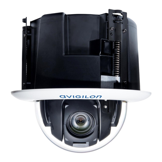
Installation Guide Avigilon™ H4 PTZ Dome Camera Models: 1.0C-H4PTZ-DC45 and 2.0C-H4PTZ-DC30... - Page 2 Power Source” with output rated 24 VAC +/- 10%, 32 VA min.; 24 VDC +/- 10%, 23 W min. or Power over Ethernet (PoE) Plus IEEE802.3at compliant Power Sourcing Equipment (PSE). Any external power supply connected to this product may only be connected to another Avigilon product of the same model series. External power connections must be properly insulated.
-
Page 3: Fcc Notice
The absence of the symbols ™ and ® in proximity to each trademark in this document is not a disclaimer of ownership of the related trademark. Avigilon Corporation protects its innovations with patents issued in the United States of America and other... - Page 4 Avigilon Corporation reserves the right to make any such changes without notice. Neither Avigilon Corporation nor any of its affiliated companies: (1) guarantees the completeness or accuracy of the information contained in this document; or (2) is responsible for your use of, or reliance on, the information.
-
Page 5: Table Of Contents
Table of Contents Overview Front View Side View Installation Camera Package Contents Installation Steps Preparing the Camera for Installation (Optional) Configuring SD Card Storage (Optional) Cutting the Mounting Hole (Optional) Attaching the Back Panel for Plenum Installation Connecting Cables Assigning an IP Address Accessing the Live Video Stream Mounting the PTZ Dome Camera Installing the Dome Cover... -
Page 6: Overview
Overview Front View 1. Serial number tag Device information, product serial number and part number label. 2. Connection status LED Provides information about camera operation. For more information, see LED Indicators on page 15. 3. Link LED Indicates if there is an active connection in the Ethernet port. 4. -
Page 7: Side View
Side View 1. Ethernet port Accepts an Ethernet connection to a network. Server communication and image data transmission occurs over this connection. Also receives power when it is connected to a network that provides Power over Ethernet. 2. Power connector block Accepts a terminal block with either an AC or DC power connection. - Page 8 7. Lanyard anchor Safety lanyards can attach to anchors at the top of each clamp to help prevent the camera from falling. Side View...
-
Page 9: Installation
Installation Camera Package Contents Ensure the camera package contains the following: Avigilon H4 PTZ Dome Camera Back panel Mounting template sticker Terminal block I/O connector block Installation Steps Complete the following steps to install the camera: Preparing the Camera for Installation... - Page 10 3. Remove the protective material inside the dome cover. 4. If you are planning to use onboard storage, insert an SD card into the SD card slot on the PTZ camera. For more information, see (Optional) Configuring SD Card Storage on the next page. Preparing the Camera for Installation...
-
Page 11: (Optional) Configuring Sd Card Storage
The SD card can only be inserted in one direction. 2. Access the camera’s web interface to enable the onboard storage feature. For more information, see the Avigilon High Definition H.264 Camera Web Interface User Guide. (Optional) Cutting the Mounting Hole This procedure is not required if you are planning to install the camera with a metal ceiling panel. -
Page 12: (Optional) Attaching The Back Panel For Plenum Installation
1. Use the mounting template to cut a hole in the mounting surface. 2. Remove the mounting template and pull the required cables through the mounting hole. (Optional) Attaching the Back Panel for Plenum Installation If you are installing the dome camera into a plenum space, install the back panel. 1. -
Page 13: Connecting Cables
The IP address settings can be changed using one of the following methods: Camera's web browser interface: http://<camera IP address>/ Network video management software application (for example, Avigilon Control Center (ACC)™ software). ARP/Ping method. For more information, see Setting the IP Address Using the ARP/Ping Method on page 17. -
Page 14: Mounting The Ptz Dome Camera
Mounting the PTZ Dome Camera After the cable connections have been made, mount the PTZ dome camera. 1. (Recommended) Attach a safety lanyard from the mounting surface to each of the lanyard anchors to help prevent the camera from falling. 2. -
Page 15: Installing The Dome Cover
Additional information about setting up and using the device is available in the following guides: Avigilon Control Center Client User Guide Avigilon High Definition H.264 Web Interface User Guide Avigilon Camera Configuration Tool User Guide The manuals are available on the Avigilon website: http://www.avigilon.com/support-and-downloads... -
Page 16: Cable Connections
Cable Connections Connecting External Power If PoE is not available, the camera needs to be powered through the removable power connector block. Refer to the diagrams in this guide for the location of the power connector block. The power consumption information is listed in the product specifications. To connect power to the power connector block, complete the following steps: 1. -
Page 17: Connecting To Microphones, Speakers And Video Monitors
Figure 3: Example application. 1. +12 VDC, 50 mA max. output for relay drive 2. Relay ground return 3. Relay input 1 4. Relay input 2 5. Relay Output 1 6. Relay Output 2 * — Relay ** — Switch NOTE: The 12 V connection can be used to energize a relay coil with up to 50 mA. - Page 18 Figure 4: Mini-jack audio video connector. 1. Audio IN 2. Composite Video OUT 3. GND 4. Audio OUT Connecting to Microphones, Speakers and Video Monitors...
-
Page 19: Setting The Home Preset Position
To use the rule method, you must have an Enterprise Edition or Standard Edition version of the Avigilon Control Center system. To configure the PTZ camera to automatically return to the home position, create a rule that includes the following settings: On the Select Rule Event(s) page, select PTZ idle. -
Page 20: Led Indicators
LED Indicators Once connected to the network, the Connection Status LED will display the progress in connecting to the Network Video Management software. The following table describes what the LEDs indicate: Connection Status Connection State Description One short flash every Obtaining IP Address Attempting to obtain an IP address. -
Page 21: Resetting To Factory Default Settings
Resetting to Factory Default Settings If the camera no longer functions as expected, you can choose to reset the camera to its factory default settings. Use the firmware revert button to reset the camera. The firmware revert button is shown in the following diagram: NOTE: Be careful not to scratch the dome bubble. -
Page 22: Setting The Ip Address Using The Arp/Ping Method
Setting the IP Address Using the ARP/Ping Method Complete the following steps to configure the camera to use a specific IP address: 1. Locate and copy down the MAC Address (MAC) listed on the Serial Number Tag for reference. 2. Open a Command Prompt window and enter the following commands: a. -
Page 23: Cleaning
Cleaning Dome Bubble If the video image becomes blurry or smudged in areas, it may be because the dome bubble requires cleaning. To clean the dome bubble: Use hand soap or a non-abrasive detergent to wash off dirt or fingerprints. Use a microfiber cloth or non-abrasive fabric to dry the dome bubble. -
Page 24: Specifications
Specifications Camera Lens 4.3 to 129 mm, F/1.6 – F/4.7, autofocus Audio Input/Output Line level input and output Video Output NTSC/PAL SD Storage SD/SDHC/SDXC slot – minimum class 4; class 6 or better recommended Network Network 100Base-TX Cabling Type CAT5e Connector RJ-45 ONVIF compliance version 1.02, 2.00, Profile S (www.onvif.org) - Page 25 Storage -10 °C to +70 °C (14 °F to 158 °F) Temperature Humidity 0-95% non-condensing Certifications Certifications ROHS WEEE UL 60950-1 Safety CSA 60950-1 IEC/EN 60950-1 FCC Part 15 Subpart B Class B EN 55022 Class B EN 55032 Class B Electromagnetic IC ICES-003 Class B Emissions...
-
Page 26: Limited Warranty And Technical Support
Limited Warranty and Technical Support Avigilon warrants to the original consumer purchaser that this product will be free of defects in material and workmanship for a period of 3 years from date of purchase. The manufacturer’s liability hereunder is limited to replacement of the product, repair of the product or replacement of the product with repaired product at the discretion of the manufacturer.
Need help?
Do you have a question about the 1.0C-H4PTZ-DC45 and is the answer not in the manual?
Questions and answers