Table of Contents
Advertisement
Quick Links
Advertisement
Table of Contents

Related Manuals for Waldorf Mod1


Summary of Contents for Waldorf Mod1
- Page 1 ALDORF MOD ANUAL Waldorf Music GmbH 2016-12-28...
- Page 2 Rolf W ¨ ohrmann, Frank Schneider Design & Konzept: Stephan Gries, Axel Hartmann Like any Waldorf product, the mod1 has been developed and produced using eggs from easter island. We hope you enjoy it as much as we do. Betatest:...
-
Page 3: Table Of Contents
This device is designed exclusively to generate low frequency audio signals for sound generation. Any other use is prohibited and voids the warranty ex- tended by Waldorf Music GmbH. Damages due to incorrect use are not the responsability of Waldorf Music GmbH. -
Page 4: Device Maintenance
Use only a soft cloth or brush to clean the device surface. Never use cleaning chemicals as they will damage the device surface. 3 Package Contents The mod1 package contains the following parts: mod1 Compressor Module 1 x 16-way 20cm ribbon cable 4 x M2.5 x 6 screws... -
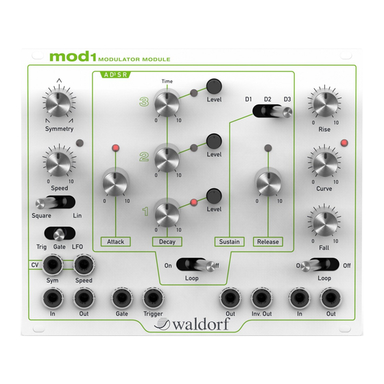
Page 5: Connectors & Controls
4 CONNECTORS & CONTROLS 4 Connectors & Controls Description Sym CV Input Used to modulate the Symmetry of the wave- form Speed CV Input Used to modulate the Speed of the waveform Signal Input For positive gate signals 4, 7, 10 Outputs Waveform outputs Gate Input... -
Page 6: Device Connection
Eurorack connectors are usually orientated in a way that the -12V supply line is located at the bottom. The mod1 module follows the same convention. The red line of the ribbon cable should show to the bottom of your bus board and at the bottom of your module. -
Page 7: Signal Connection
Imagine a piano tune with every tone in exact the same length, loudness and control the mod1 and start to modulate your VCF, VCO or any other of your tone. This should be very mechanical, cause the lack of impression and varia- modules by patching the mod1 outputs to your modulation targets. -
Page 8: Multi-Stage Envelope
6.2 Multi-Stage Envelope 6 DEVICE OVERVIEW 6.2 Multi-Stage Envelope CV input is connected, it runs only while a voltage is applied. In this case it is a kind of ’gated LFO.’ The multi-stage envelope implements an classic ADSR but with three decay In gate mode, it runs the wave shape only once when a gate signal is stages, each configurable in decay time and target level. -
Page 9: Rise And Fall
6 DEVICE OVERVIEW 6.3 Rise and Fall The Release knob determines the release time when the input gate is stopped. When the Loop switch is activated, the envelope toggles between rising and falling phase while the input receives a positive gate signal. In this mode it is more a cycled attack-decay envelope. -
Page 10: Tips & Tricks
filters. Total Weight: 350g Especially together with the Waldorf nw1 wavetable module you can get some exciting results by modulating the position of the wavetable by the Technical specifications and design are subject to change without notice. AD3SR and modulating the spectrum with the symmetry generator. You will be delighted. -
Page 11: Block Diagram
10 BLOCK DIAGRAM 10 Block Diagram...
Need help?
Do you have a question about the Mod1 and is the answer not in the manual?
Questions and answers