Table of Contents
Advertisement
Use, features
Use
Features
CC1N7101en
29.06.2006
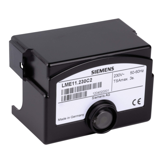
Gas Burner Controls
Gas burner controls for the supervision of 1- or 2-stage gas burners of small to
medium capacity (typically up to 350 kW), in intermittent operation.
The LME... and this Data Sheet are intended for use by OEMs which integrate the
burner controls in their products.
LME... burner controls are used for the startup and supervision of 1- or 2-stage gas
burners in intermittent operation. The flame is supervised by an ionization probe or
flame detector QRA... with ancillary unit AGQ3... or blue–burning flames with blue-
flame detectors QRC...
In terms of housing dimensions, the LME... are identical with the LGB... and LMG...
burner controls (refer to «Type summary»).
Burner controls conforming to EN 298
-
For gas burners with fans conforming to EN 676
-
Undervoltage detection
-
Air pressure supervision with functional check of the air pressure switch during
-
startup and operation
Electrical remote reset facility
-
Multicolor indication of fault status and operational status messages
-
Limitation of the number of repetitions
-
Accurate control sequence thanks to digital signal handling
-
Controlled intermittent operation after 24 hours of continuous operation
-
7
101
LME...
Building Technologies
HVAC Products
Advertisement
Table of Contents


Need help?
Do you have a question about the LME11 series and is the answer not in the manual?
Questions and answers