Advertisement
Quick Links
Use
CC1N7153en
22.05.2014
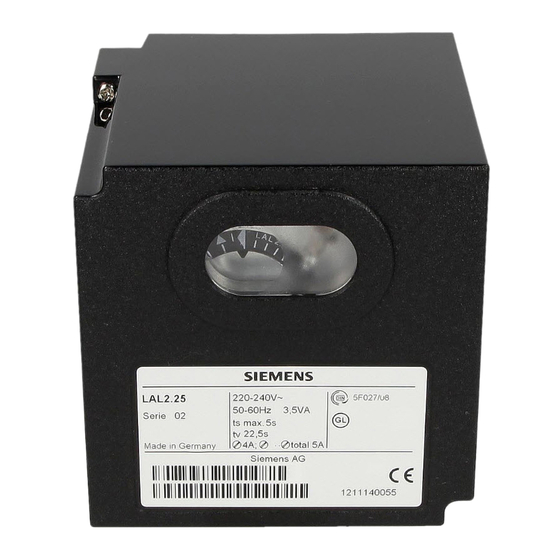
Oil Burner Controls
Oil burner controls
With or without air pressure supervision for checked air damper control
Flame supervision
– with photoresistive detector QRB...
– or blue-flame detector QRC1...
– or silicon photocell detector RAR9...
The LAL... and this Data Sheet are intended for OEMs which integrate the oil
burner controls in their products!
-
For the control and supervision of oil atomization burners
-
For burners of medium to high capacity
For intermittent operation (at least one controlled shutdown every 24 hours)
-
Can be universally used with multistage or modulating burners
-
-
Suited for use with stationary air heaters
LAL1...
- Yellow- and blue-flame burners without air pressure supervision
LAL2...
- Yellow-flame burners with air pressure supervision
LAL3.25
- For special applications, e.g. burners of incinerator plant
(for details, refer to «Type summary» and «Notes»)
For burner controls used in connection with burners for continuous operation, refer to
Data Sheet 7785 (LOK16...).
Building Technologies Division
Infrastructure & Cities Sector
7
153
LAL...
Advertisement


Need help?
Do you have a question about the LAL Series and is the answer not in the manual?
Questions and answers