
Subscribe to Our Youtube Channel
Related Manuals for Hunter GSP9200 Series

Summary of Contents for Hunter GSP9200 Series
- Page 1 OPERATION INSTRUCTIONS Form 5393-T, 11-08 Supersedes Form 5393T, 09-08 GSP9200 Series Computerized LCD Balancer With SmartWeight ® Balancing Technology Software Version © Copyright 2006 - 2008 Hunter Engineering Company...
- Page 3 OWNER INFORMATION Model Number____________________________________________________________________ Software Version Number __________________________________________________________ Serial Number ____________________________________________________________________ Date Installed ____________________________________________________________________ Service and Parts Representative_____________________________________________________ Phone Number ___________________________________________________________________ Sales Representative ______________________________________________________________ Phone Number ___________________________________________________________________ Concept and Procedure Training Checklist Trained Declined † † Safety Precautions ® Quick-Thread ®...
-
Page 5: Table Of Contents
Mounting Error Detection Features..............11 Front/Back Cone Mounting .................. 11 Using Plastic Wheel Mounting Washer..............12 Cone/Flange Plate Mounting ................14 Using the Pressure Ring and Spacers..............15 Pressure Ring....................15 Spacers ......................15 CONTENTS x i GSP9200 Series Wheel Balancer Operation Instructions... - Page 6 5.2 Program Cartridge Removal and Installation............55 5.3 Balancer Set Up......................56 Display Language ....................56 Printer........................56 Printout Language....................56 Printout Paper Size Selection ................56 Hood Autostart Feature..................56 Servo-Stop ......................56 ii x CONTENTS GSP9200 Series Wheel Balancer Operation Instructions...
- Page 7 BDC Laser Adhesive Weight Locator Maintenance or Service ......69 Optional HammerHead™ TDC Laser Clip-On Weight Locator Maintenance or Service ......................... 69 6.6 Mounting Cone Maintenance ................... 70 7. GLOSSARY....................71 CONTENTS x iii GSP9200 Series Wheel Balancer Operation Instructions...
- Page 8 CONTENTS GSP9200 Series Wheel Balancer Operation Instructions...
-
Page 9: Getting Started
1.1 Introduction This manual provides operation instructions and information required to operate the GSP9200 Series Balancer. Read and become familiar with the contents of this manual prior to operating the GSP9200. The owner of the GSP9200 is solely responsible for arranging technical training. The GSP9200 is to be operated only by a qualified trained technician. -
Page 10: Important Safety Instructions
Keep all instructions permanently with the unit. Keep all decals, labels, and notices clean and visible. To prevent accidents and/or damage to the balancer, use only Hunter GSP9200 Series Vibration Control System recommended accessories. Use equipment only as described in this manual. -
Page 11: Electrical
Decal 128-605-2-00 cautions the user that spindle rotation may occur with foot pedal ® depression and to keep clear of clamping components during Quick-Thread shaft rotation. Auto-Clamp models will have decal 128-1123-2 instead. 1. Getting Started x 3 GSP9200 Series Wheel Balancer Operation Instructions... -
Page 12: Left Side View
Decal 128-229-2 and decal 128-905-2 work in conjunction to caution the user to not remove the screw because of the risk of electrical shock. 4 x 1. Getting Started GSP9200 Series Wheel Balancer Operation Instructions... -
Page 13: Specific Precautions/Bdc Laser Indicator
NEMA L6-20P. This machine must be connected to a 20 amp branch circuit. Please refer all power source issues to a certified electrician. Refer to “Installation Instructions for GSP9200 Series Vibration Control System,” Form 5110T. -
Page 14: Turning Power On/Off
This equipment contains no user serviceable parts. All repairs must be referred to a qualified Hunter Service Representative. NOTE: To replace program cartridge, refer to “Program Cartridge Removal and Installation,” page 55. 6 x 1. Getting Started GSP9200 Series Wheel Balancer Operation Instructions... -
Page 15: Equipment Specifications
These symbols may appear on the equipment. Alternating current. Earth ground terminal. Protective conductor terminal. ON (supply) condition. OFF (supply) condition. Risk of electrical shock. Stand-by switch. Not intended for connection to public telecommunications network. 1. Getting Started x 7 GSP9200 Series Wheel Balancer Operation Instructions... -
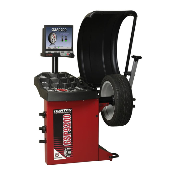
Page 16: Gsp9200 Components
1.3 GSP9200 Components 8 x 1. Getting Started GSP9200 Series Wheel Balancer Operation Instructions... - Page 17 Adhesive Weight Scraper 223-68-1 Pressure Ring 65-72-2 Calibration Weight NOTE: Hunter wheel balancers do not include a standardized set of mounting adaptors. For optional accessories, refer to Wheel Balancer Brochure, Form 3203T. Standard Accessories for Optional Auto-Clamp™ Kit 20-2077-1 106-82-2...
-
Page 18: Operating The Console
The control knob is located to the right of the softkeys. The control knob accesses the on-screen switches and manually inputs data. The available on-screen switches are dependent upon the setup configuration of the balancer. 10 x 1. Getting Started GSP9200 Series Wheel Balancer Operation Instructions... -
Page 19: Primary Balancing Display
This prevents a single accidental keystroke from resetting the system. When the balancer is reset, the information collected for the wheel balance in progress is erased and the display returns to the “Logo” screen. 1. Getting Started x 11 GSP9200 Series Wheel Balancer Operation Instructions... -
Page 21: Balancing Overview
This is not a recommended practice and usually insures the assembly is not properly dynamically balanced. The assembly may then experience side-to-side imbalance while in motion, causing a shimmy condition and objectionable vibration. 2. Balancing Overview x 1 GSP9200 Series Wheel Balancer Operation Instructions... -
Page 22: Balancing Theory - Couple Imbalance
Dynamic balancers direct the operator to place correction weights on the inside and outside correction locations of the rim so that both imbalance shake (static) and imbalance wobble (couple) will be eliminated. 2 x 2. Balancing Overview GSP9200 Series Wheel Balancer Operation Instructions... -
Page 23: Decal Information And Placement
® NOTE: SmartWeight balancing performs this check automatically. For detailed information on adjustment and setup of modes of wheel balancing sensitivity see Chapter 4, Balancing Features and Options. 2. Balancing Overview x 3 GSP9200 Series Wheel Balancer Operation Instructions... -
Page 24: Smartweight Dynamic Weight Planes
The SmartWeight tire graphs will display red for excessive forces and green for acceptable amounts of force. Prior to measurement the tire graphs will display no color. 4 x 2. Balancing Overview GSP9200 Series Wheel Balancer Operation Instructions... -
Page 25: Switching From Smartweight
The following example is set at the default of 75%. A 75% residual goal ® means that WeightSaver allows 75% of the maximum allowed couple force to remain. This saves more weight, saves time, and saves money. 2. Balancing Overview x 5 GSP9200 Series Wheel Balancer Operation Instructions... -
Page 26: Equipment Installation And Service
If the wheel has no appreciable movement around or about the centerline of the hub, it should be considered hub centric. A hub centric wheel will have very little (0.003 – 0.004”) clearance or a slip fit to the hub. 6 x 2. Balancing Overview GSP9200 Series Wheel Balancer Operation Instructions... -
Page 27: Lug Centric
To verify if the wheel is lug centric: Remove the lug nuts (or bolts) and try to move the wheel up/down and side/side on the hub. A lug centric wheel will display noticeable movement. 2. Balancing Overview x 7 GSP9200 Series Wheel Balancer Operation Instructions... -
Page 29: Standard Accessories For Quick-Thread
Slowly roll the wheel towards you while tightening the wing nut. This improves accurate wheel centering, since the wheel is allowed to roll up the taper of the cone as opposed to forcing it to slide up the cone. 3. Balancing Procedures x 9 GSP9200 Series Wheel Balancer Operation Instructions... -
Page 30: Using Control Knob
To remove the Auto-Clamp assembly, slightly tap the Spindle-Lok® foot pedal twice to release the pneumatically powered spindle. Squeeze the levers to disconnect the Auto-Clamp locks from the spindle, and slide the assembly off the spindle. 10 x 3. Balancing Procedures GSP9200 Series Wheel Balancer Operation Instructions... -
Page 31: Mounting Error Detection Features
STANDARD WHEEL WHEEL MOUNTING CONE SPINDLE SHAFT WING NUT CAPTIVATED SPRING STANDARD STEEL PLASTIC INSIDE WHEEL RIM CLAMPING SURFACE 3. Balancing Procedures x 11 GSP9200 Series Wheel Balancer Operation Instructions... -
Page 32: Using Plastic Wheel Mounting Washer
LARGE OFFSET WHEEL MOUNTING PLASTIC CONE WASHER SPINDLE SHAFT WING NUT CAPTIVATED PLASTIC SPRING NOTE: Use only the wing nut supplied with the GSP9200. 12 x 3. Balancing Procedures GSP9200 Series Wheel Balancer Operation Instructions... - Page 33 (2) use of optional wheel lift to position heavy wheel onto shaft and cone. This helps the wheel to overcome gravity against the hub or spacer. 3. Balancing Procedures x 13 GSP9200 Series Wheel Balancer Operation Instructions...
-
Page 34: Cone/Flange Plate Mounting
This statement is true for many wheels including hub centric wheels. That is why a flange plate and back cone may be more accurate and repeatable, regardless of whether the wheel is lug centric or hub centric. 14 x 3. Balancing Procedures GSP9200 Series Wheel Balancer Operation Instructions... -
Page 35: Using The Pressure Ring And Spacers
Use the smaller cone size, with the spacer, to extend the captivated spring and hold the smaller mounting cone against the wheel opening with greater pressure. 3. Balancing Procedures x 15 GSP9200 Series Wheel Balancer Operation Instructions... -
Page 36: Balance Primary Screen
The “Set Dimensions” view enlarges the dimensional diagram of the wheel assembly. The inch/millimeter selection softkeys are available in this view on the first row menu. The control knob can be used to manually enter the rim dimensions 16 x 3. Balancing Procedures GSP9200 Series Wheel Balancer Operation Instructions... -
Page 37: Wheel Assembly Selection For Saving Spin Data
Balance assembly and continue to the next assembly. The “Store Measurements” screen will automatically progress to the next assembly in a clockwise direction. Repeat “Store Measurements” until all assemblies are complete. 3. Balancing Procedures x 17 GSP9200 Series Wheel Balancer Operation Instructions... -
Page 38: Print Summary
Select “Print” to send before and after balance summary results to the printer. 3.4 Balance Modes Select the correct balance mode for each application using the control knob. Refer to “Using the Control knob,” page 10. 18 x 3. Balancing Procedures GSP9200 Series Wheel Balancer Operation Instructions... -
Page 39: Smartweight Balancing Technology
Dynamic will always display two weight planes. Dynamic balancing provides a more complete balance than static balancing. Dynamic balancing should be selected whenever possible to minimize vehicle vibration. Refer to “Balancing Theory-Couple Imbalance,” page 2. 3. Balancing Procedures x 19 GSP9200 Series Wheel Balancer Operation Instructions... -
Page 40: Static Balancing - Traditional Balancing Mode
The first screen gives the warning: “Avoid STATIC single-plane balancing.” The second screen suggests: “DYNAMIC dual-plane balancing recommended (even for hidden weights).” If STATIC is selected, the reminders show up again at the end of the spin. 20 x 3. Balancing Procedures GSP9200 Series Wheel Balancer Operation Instructions... -
Page 41: Balancing Procedures For Specific Weight Types And Placement
Selecting AUTO MODE will choose the correct weight type and placement for the specific wheel. AUTO MODE incorporates procedures of specific wheel balance methods as outlined on the following pages. 3. Balancing Procedures x 21 GSP9200 Series Wheel Balancer Operation Instructions... -
Page 42: Standard Balancing Procedure Using Clip-On Weights
The GSP9200 will find the TDC for the left weight plane if “Servo-Stop” is enabled. “Servo-Stop” will hold the wheel in the TDC position while the weight is applied. The weight amount will be displayed in green. 22 x 3. Balancing Procedures GSP9200 Series Wheel Balancer Operation Instructions... - Page 43 If necessary, use the right “ ” to split the weight. Refer to “Split Weight Feature,” page 41. Left and right weight plane displays should show “OK” after checkspin. STANDARD balancing procedure is complete. 3. Balancing Procedures x 23 GSP9200 Series Wheel Balancer Operation Instructions...
-
Page 44: Mixed Weights Balancing Procedure Using A Combination Of Clip-On & Adhesive Weights
The GSP9200 will find the TDC for the left weight plane if “Servo-Stop” is enabled. “Servo-Stop” will hold the wheel in the TDC position while the weight is applied. 24 x 3. Balancing Procedures GSP9200 Series Wheel Balancer Operation Instructions... - Page 45 The laser turns off when the wheel is spun again. CAUTION: Use of controls or adjustments or performance of procedures other than those specified herein may result in hazardous radiation exposure. 3. Balancing Procedures x 25 GSP9200 Series Wheel Balancer Operation Instructions...
-
Page 46: Adhesive Weights Balancing Procedure Using Adhesive Weights
Select either grams or ounces by rotating the control knob and highlighting either “g” or “oz.” Select “DYNAMIC” by rotating the control knob to highlight “ .” Refer to “Dynamic ® Balancing,” page 19, if SmartWeight is enabled. 26 x 3. Balancing Procedures GSP9200 Series Wheel Balancer Operation Instructions... - Page 47 LCD. Refer to “Servo-Aided Adhesive Weight Placement,” page 33. If servo is not enabled, BDC placement should be used. Refer to “Manual Weight Position Measurement,” page 31. 3. Balancing Procedures x 27 GSP9200 Series Wheel Balancer Operation Instructions...
-
Page 48: Patch Balance Procedure
Weighted balance patches should be installed only in tread area. Do not install weighted balance patches near sidewall or shoulder of tire. Verify that the wheel is clean and free of debris. 28 x 3. Balancing Procedures GSP9200 Series Wheel Balancer Operation Instructions... - Page 49 Place outer Dataset arm roller directly over the right mark and enter data by depressing the foot pedal. Close safety hood. Press the green “START” button if “Hood Autostart” is disabled. 3. Balancing Procedures x 29 GSP9200 Series Wheel Balancer Operation Instructions...
-
Page 50: Automatic Dataset Arms Operation
Arms are used to input the exact weight position. The exact weight position is entered by holding the arm(s) stable in the desired location and depressing the foot pedal to enter the dimensional data. 30 x 3. Balancing Procedures GSP9200 Series Wheel Balancer Operation Instructions... -
Page 51: Manual Weight Position Measurement
While on the “Set Dimensions” view of the “Balance” primary screen, the control knob can be used to enter rim dimensions manually. ® Hunter Engineering Company recommends using the inner and outer Dataset arms ® to enter dimensions. Refer to “Using the Auto Dataset Arms,”... -
Page 52: Measuring Dimensions For Mixed Weights (Clip-On/Adhesive) Balance
Depress the foot pedal to enter the dimensional data. The GSP9200 will beep to confirm data entry. ® Do NOT return Dataset arm to the home position. 32 x 3. Balancing Procedures GSP9200 Series Wheel Balancer Operation Instructions... -
Page 53: Servo-Aided Adhesive Weight Placement
® ® inner Dataset arm. Pull the inner Dataset arm out from the base until the arm and the weight location are overlapping. 3. Balancing Procedures x 33 GSP9200 Series Wheel Balancer Operation Instructions... -
Page 54: Manual Adhesive Weight Placement
The BDC laser locator automatically displays a vivid line at bottom dead center after a wheel has been spun. The laser turns off when the wheel is spun again. The weight should be placed at BDC at that distance. 34 x 3. Balancing Procedures GSP9200 Series Wheel Balancer Operation Instructions... -
Page 55: Centeringcheck
On-screen prompts lead you through the procedure. Select “Perform Centering Check” from the menu. Follow the on-screen prompts. Position the valve stem at 12 o’clock, and then press “Enter Valve Stem.” 3. Balancing Procedures x 35 GSP9200 Series Wheel Balancer Operation Instructions... - Page 56 If the rim is centered properly, the following screen will appear briefly. The GSP9200 will then proceed to the “Balance” screen. If a centering problem is detected, the following screen will appear. 36 x 3. Balancing Procedures GSP9200 Series Wheel Balancer Operation Instructions...
- Page 57 Correct mounting cone/adaptor for this wheel design. Wheel defect such as a metal burr interfering with the cone/adaptor. Dirt or debris interfering with the cone/adaptor. Follow the on-screen prompts, and then press “Restart Procedure.” 3. Balancing Procedures x 37 GSP9200 Series Wheel Balancer Operation Instructions...
-
Page 59: Balancing Features And Options
® the spindle and to allow maximum Quick-Thread wing nut travel. Place the wing nut on the spindle and rotate one full turn onto the spindle threads. 4. Balancing Features and Options x 39 GSP9200 Series Wheel Balancer Operation Instructions... -
Page 60: Auto-Clamp™ Wheel Clamping (Optional)
Servo-Stop can be enabled or disabled from the “Set Up” primary screen. Refer to “Servo-Stop,” page 56. 40 x 4. Balancing Features and Options GSP9200 Series Wheel Balancer Operation Instructions... -
Page 61: Spindle-Lok Feature
4. Balancing Features and Options x 41 GSP9200 Series Wheel Balancer Operation Instructions... -
Page 62: Split Weight Operation
2.25 ounce weight. Then place the two indicated ounce weights on either side of the 2.25 ounce weight using the TDC indicators. 42 x 4. Balancing Features and Options GSP9200 Series Wheel Balancer Operation Instructions... -
Page 63: Split Spoke ® Feature
Enter the data by pressing the foot pedal. ® Return the inner Dataset arm to the home position. Close safety hood. Press the green “START” button if “Hood Autostart” is disabled. 4. Balancing Features and Options x 43 GSP9200 Series Wheel Balancer Operation Instructions... -
Page 64: Re-Entering Similar Wheel After Split Spoke Is Enabled
“Set New Spoke Location” key to input the spoke orientation of the other three rims from a set to avoid re-measuring the weight plane dimensions each time. 44 x 4. Balancing Features and Options GSP9200 Series Wheel Balancer Operation Instructions... -
Page 65: Placing Hidden Weight Inside Of Hollow Spokes
This distance must be in millimeters (convert inches to millimeters by multiplying by 25.4). Measure the weight plane diameter manually, using caliper or tape measure. 4. Balancing Features and Options x 45 GSP9200 Series Wheel Balancer Operation Instructions... -
Page 66: Rimscan™ Wheel Profile Scanner
® RimScan is available only if SmartWeight is enabled. RimScan is designed for adhesive weights or mixed weight balancing methods. 46 x 4. Balancing Features and Options GSP9200 Series Wheel Balancer Operation Instructions... -
Page 67: Setting Dimensions With Rimscan
RimScan. ® To initiate RimScan, pull the inner Dataset arm away from the weight tray and turn to the down position. 4. Balancing Features and Options x 47 GSP9200 Series Wheel Balancer Operation Instructions... - Page 68 When the scan is complete, release the foot pedal and a rim illustration will appear with weight planes automatically placed at correct positions for tapers or steps. 48 x 4. Balancing Features and Options GSP9200 Series Wheel Balancer Operation Instructions...
- Page 69 Select “Find Best Location” to let the balancer decide what is the optimum corrective weight location. If by chance the user-selected weight positions are unacceptable, “Find Best Location” will return the weights to the optimum positions. 4. Balancing Features and Options x 49 GSP9200 Series Wheel Balancer Operation Instructions...
-
Page 70: Real-Time Predictions With Rimscan And Smartweight
As ® the position changes, the SmartWeight force graphs will display a prediction of the force results corresponding to the weight. 50 x 4. Balancing Features and Options GSP9200 Series Wheel Balancer Operation Instructions... -
Page 71: Bdc Laser Adhesive Weight Locator
The HammerHead™ TDC Laser System automatically displays a vivid line at top dead center after a wheel has been spun. The laser turns “off” when the wheel is spun again. 4. Balancing Features and Options x 51 GSP9200 Series Wheel Balancer Operation Instructions... - Page 72 Operation accessible radiation fields: Wavelength 635-660nm Laser Power for Classification <1mW via 7mm aperture Beam Diameter <5mm at aperture Divergence <1.5mrad x <2rad Transverse Beam Mode TEM00 52 x 4. Balancing Features and Options GSP9200 Series Wheel Balancer Operation Instructions...
-
Page 73: Specific Precautions / Hammerhead™ Tdc Laser System
Specific Precautions / HammerHead™ TDC Laser System Use caution in regard to reflective materials around the laser and never look into the laser beam 4. Balancing Features and Options x 53 GSP9200 Series Wheel Balancer Operation Instructions... -
Page 74: Print Summary
Imbalance condition is printed. Split and Spoke weight values are printed as the single weight equivalent (better indication of imbalance since weight angles are not printed). 54 x 4. Balancing Features and Options GSP9200 Series Wheel Balancer Operation Instructions... -
Page 75: Equipment Information
Press “Store Setup” to complete “Setup” procedures. NOTE: If indicated after installation, the GSP9200 must be completely re-calibrated after program cartridge installation. Refer to “Calibration Procedures,” page 61. Calibration tool, 221-672-1, is required. 5. Equipment Information x 55 GSP9200 Series Wheel Balancer Operation Instructions... -
Page 76: Balancer Set Up
This will immediately return the user to the main screen and “Service Mode” will then be displayed at the top of the screen. “Service Mode” enables the selection of advanced customized settings and hardware specific setup. 56 x 5. Equipment Information GSP9200 Series Wheel Balancer Operation Instructions... -
Page 77: Set Date And Time
Selects the amount to which gram weights are rounded. Gram Round Amount options include 1 gram, and 5 grams. Setting the Limits Displayed ® Limits Displayed switches the SmartWeight settings between Normal Assemblies and Large Assemblies. 5. Equipment Information x 57 GSP9200 Series Wheel Balancer Operation Instructions... -
Page 78: Non-Smartweight Options
The Residual Goal has a default of 75% of the maximum allowed shimmy force to maximize weight savings. Prompt for Wheel Assembly ID Enables or disables prompting of the user to enter the current assembly before saving. 58 x 5. Equipment Information GSP9200 Series Wheel Balancer Operation Instructions... -
Page 79: Spindle Type
Spindle Type Sets the spindle to the correctly installed spindle type. Select either the standard threaded spindle or the optional Auto-Clamp pneumatic spindle. HammerHead™ Setup options for the HammerHead option. 5. Equipment Information x 59 GSP9200 Series Wheel Balancer Operation Instructions... -
Page 81: Calibration And Maintenance
® Dataset arm require the optional calibration tool, 221-672-1. 6. Calibration and Maintenance x 61 GSP9200 Series Wheel Balancer Operation Instructions... -
Page 82: Balancer (3 Spin Procedure)
If calibration succeeds, the LCD will display a “Calibration Complete” message. If calibration fails, such as if the weight was placed incorrectly during the procedure, the GSP9200 will keep previous balancer calibration data. 62 x 6. Calibration and Maintenance GSP9200 Series Wheel Balancer Operation Instructions... -
Page 83: Inner Dataset ® Arm (Calibration Tool, 221-672-1, Required)
Press “OK” when calibration tool is installed. Rotate the calibration tool slowly by hand, clockwise until the GSP9200 beeps. NOTE: You may have to rotate the tool up to 1 1/2 turns. 6. Calibration and Maintenance x 63 GSP9200 Series Wheel Balancer Operation Instructions... - Page 84 “4.” Tap the foot pedal once or press “Enter Cal Step.” ® Place the inner Dataset arm at downward position “5.” Tap the foot pedal once or press “Enter Cal Step.” 64 x 6. Calibration and Maintenance GSP9200 Series Wheel Balancer Operation Instructions...
-
Page 85: Outer Dataset ® Arm (Calibration Tool, 221-672-1, Required)
With the hood in the raised position, verify that the outer arm is in the “home” position and that the arm and hood are not moving. Tap the foot pedal once or press “Enter Cal Step.” 6. Calibration and Maintenance x 65 GSP9200 Series Wheel Balancer Operation Instructions... - Page 86 Place the outer Dataset® arm at position “5.” Tap the foot pedal once or press “Enter Cal Step.” Place the outer Dataset® arm at position “6.” Tap the foot pedal once or press “Enter Cal Step.” Outer Dataset® arm calibration is complete. 66 x 6. Calibration and Maintenance GSP9200 Series Wheel Balancer Operation Instructions...
-
Page 87: Quick Calibration Check Procedure
GSP9200. Begin diagnostic procedures by selecting “Begin Selected Test.” To exit a diagnostic procedure, select “End This Test.” 6. Calibration and Maintenance x 67 GSP9200 Series Wheel Balancer Operation Instructions... -
Page 88: Force Sensors
Most of the diagnostic data is available for the sole purpose of conveying information to your Hunter Service Representative. Your service representative may request information from these screens to diagnose service concerns. The ability to convey diagnostic data to the representative prior to servicing the GSP9200 will expedite service to your equipment. -
Page 89: Maintenance
Do not operate the laser if the cover or seal is damaged. There is no required maintenance or service to keep the HammerHead™ TDC Laser System in compliance. The laser is not a field serviceable or an adjustable part. 6. Calibration and Maintenance x 69 GSP9200 Series Wheel Balancer Operation Instructions... -
Page 90: Mounting Cone Maintenance
Do not use cones in any way that is not described in this operation manual. This could cause damage to the mounting cone and not allow for proper mounting of the wheel. 70 x 6. Calibration and Maintenance GSP9200 Series Wheel Balancer Operation Instructions... -
Page 91: Glossary
Dynamic Balance A procedure that balances the wheel assembly by applying correction weights in two planes so that up and down imbalance and side to side imbalance are eliminated. 7. Glossary x 71 GSP9200 Series Wheel Balancer Operation Instructions... - Page 92 Allows the operator to match up four identical tires on identical rims, to achieve the optimal combination of match mounting. Natural Frequency The point at which an object will vibrate the easiest. 72 x 7. Glossary GSP9200 Series Wheel Balancer Operation Instructions...
- Page 93 Measurement. The load roller places up to 1400 pounds of force on the spinning tire, and automatically measures the effects of loaded runout and tire stiffness to emulate tire/wheel assembly force variation. 7. Glossary x 73 GSP9200 Series Wheel Balancer Operation Instructions...
- Page 94 The measured distance between the mounting face of the wheel and the centerline of the rim. Wheel Width Dimension measured on the inside of the rim between the bead seats. 74 x 7. Glossary GSP9200 Series Wheel Balancer Operation Instructions...
- Page 96 Busses and RVs are discussed. Hunter University’s eLearning courses are designed for all student levels and can be used as an integral supplement to instructor-led training courses. In-depth information, detailed graphics, video and modular segments assist the participant in expanding their knowledge base at a self-determined level.
Need help?
Do you have a question about the GSP9200 Series and is the answer not in the manual?
Questions and answers