Leica TPS1100 Professional Series User Manual
Hide thumbs
Also See for TPS1100 Professional Series:
- Reference manual (240 pages) ,
- User manual (1154 pages)
Advertisement
Quick Links
Advertisement

Subscribe to Our Youtube Channel
Related Manuals for Leica TPS1100 Professional Series


Summary of Contents for Leica TPS1100 Professional Series
- Page 2 Congratulations on your purchase of a TPS1100 Professional Series instrument. This manual contains important safety directions ( refer to chapter "Safety directions" ) as well as instructions for setting up the product and operating it. Read carefully through the User Manual before you switch on the...
- Page 3 The instrument model and the serial number of your product are indicated on the label in the battery compartment. Enter the model and serial number in your manual and always refer to this information when you need to contact your agency or authorized service workshop.
- Page 4 The symbols used in this User Manual have the following meanings: DANGER: Indicates an imminently hazardous situation which, if not avoided, will result in death or serious injury. WARNING: Indicates a potentially hazardous situation or an unintended use which, if not avoided, could result in death or serious injury. CAUTION: Indicates a potentially hazardous situation or an unintended use which, if not avoided, may result in minor or moderate injury and / or...
- Page 5 Contents Introduction Description of the system Preparation, setting up Checking and adjusting Systemic functions Systems parameters Data format Care and transport Safety directions Technical specifications Index...
- Page 6 RCS (Remote Controlled Surveying) ......16 Tripod ................41 System concept ............17 Bull's eye bubble on instrument ........41 Leica SurveyOffice PC software package ....19 Bull's eye bubble on the tribrach ........41 Batteries and chargers ..........20 Optical plummet ............. 42 Laser plummet ..............
- Page 7 Displaying and editing GSI data (SEARC) ...... 51 Manual distance entry ............. 72 Placeholder (wild cards) in searching for points ....52 Positioning the last point stored (LAST) ......73 Manual input of coordinates (INPUT) ......53 Release of V-angle (V RUN) ........... 73 Converting data ..............
- Page 8 Measurement parameters ......... 92 System parameters ........87 Pt. Id. mode ..............92 General parameters ..........87 Offs. Mode ..............92 Date ................87 Increment ............... 93 Date form................ 87 Work settings ............94 Time ................87 Meas Job ................ 94 Time form.
- Page 9 Care and transport ........106 Technical specifications ......124 Transport ..............106 EGL Guide Light ............128 Storage ..............107 Automatic Target Recognition ATR ......129 Cleaning and drying ..........107 Application programs ..........130 Scale correction (ppm) ..........131 Safety directions ........
- Page 10 In ATR mode the fine- pointing is automatic. In LOCK mode Leica Geosystems offers The R versions have a laser with a an already-targeted point is tracked applications programs for many dif- visible red beam. The EDM can be automatically.
- Page 11 • User manual: General text applies to all types. This includes all directions for Leica Survey Office is a using the instrument and provides PC-program package which supports For purposes of pictorial illustration, an overview of the system together...
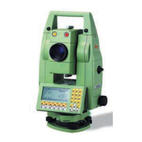
- Page 12 1 Carrying handle 2 Optical sight 3 Telescope with integrated EDM, ATR and EGL 4 EGL flashing diode (yellow) 5 EGL flashing diode (red) 6 Coaxial optics for angle- and distance measurement; Exit port of visible laser beam (only R-model instruments) 7 Vertical drive screw 8 Focusing ring 9 PC-card housing...
- Page 13 A laser distancer (EDM) is This will occur because reflectorless incorporated into the instruments of measurements are made to the first the new TPS1100 series. surface returning sufficient energy to allow the measurement to take place. In all versions, the distance can be For example, if the intended target determined by using an invisible surface is the surface of a road, but a...
- Page 14 TCA and TCRA instruments are As with all other instrument LOCK mode motorized and equipped with errors, the collimation error Automatic Target Recognition (ATR) of the automatic target recognition Lock mode will enable TCA coaxially in the telescope. The guide (ATR) must be redetermined instruments to follow a moving prism.
- Page 15 The optionally available Guide Light At a target distance of 100 metres EGL consists of two coloured (330 ft) a red/yellow flashing cone of flashing lights in the telescope of the light with a width of 6m (20 ft) is total station.
- Page 16 The RCS option (Remote Controlled Combined operation, partly at the For further information, refer Surveying) permits all models to be TPS1100 and partly at the prism, is to the RCS1100 user controlled from the target area. also possible. manual. Especially qualified for this purpose As a result, surveys can be are the TCA and TCRA instruments.
- Page 17 If you need a particular Using the Leica SurveyOffice language version, please ask your software provided, both the system agency about its availability. software and the applications...
- Page 18 Storage concept and data flow GeoBasic Instead of using the PC card, the data can be output in GSI format at The GeoBasic development the serial data interface. environment permits the professional development of additional applications for the TPS1100. When data is transferred across the serial interface for storage in an external PC, no data from the applications is output in the...
- Page 19 • Data Exchange Manager: please refer to the Installing in the PC Exchange of data between the comprehensive on-line help. The installation program for Leica instrument and the PC. SurveyOffice is located on the • Codelists Manager: TPS1100 CD-ROM supplied with the Creates code lists.
- Page 20 Adapter plate Adapter plate GEB121 GDI121 GDI121 Your Leica Geosystems instrument is The Professional charger (GKL122) The adapter plate can be connected powered by rechargeable battery will charge up to four batteries, either to the Pro charger (GKL122) or to the modules.
- Page 21 Take the instrument out of the transport container and check that it is complete: 1 PC cable (optional) 2 Eyepiece for steep sights / Zenith eyepiece (optional) 3 Counterweight for eyepiece for steep sights (optional) 4 Charger GKL111 (optional) 5 PC card (optional) 6 Pocket knife (optional) 7 Auxiliary lens (optional) 8 Spare battery (optional)
- Page 22 To attain full battery Charger capacitance, it is essential to GKL122 subject new GEB111 / GEB121 batteries to between three and five complete charge/discharge cycles. Adapter plate Charger GKL111 GDI121 The battery chargers GKL111 or The battery chargers are GKL122 are used to charge the intended for indoor use only.
- Page 23 Insert battery correctly (note pole markings on the inside of the battery cover). Check and insert battery holder true to side into the housing. 1. Remove battery holder. 3. Insert battery into battery holder. 2. Remove battery and replace. 4. Insert battery holder into instrument.
- Page 24 If you need additional ferrite cores, The Lemo plug with the please contact your local Leica Geo- ferrite core always has to be systems agency. The spare-part attached at the instrument side. number of the ferrite core is 703 707.
- Page 25 5/8"-thread Tribrach GDF121 or GDF122 Tripod GST120 1. Target the ground point or activate 3. Using the footscrews of the 5. Level-up precisely, using the the laser plummet. tribrach, centre the plummet to the electronic bubble ( see the chapter "Levelling-up with the electronic 2.
- Page 26 Graphical and Using the footscrews, the instrument When the bubble is centred, the numerical display of the can be levelled-up without having to TPS1100 has been perfectly levelled longitudinal and transverse tilt of the turn it through 90° (100 gon) or 180° instrument’s vertical axis.
- Page 27 All instruments basically have The instrument errors listed on the The determination of the inherent mechanical defects which left can change over time and with instrument errors can be can affect the measurement of temperature. started in any telescope face. angles.
- Page 28 Activating the "Instrument calibration" Joint determination of the V- The instrument errors reported are function. index errors, line-of-sight displayed in the sense of an error. errors and, if required, tilting- When measurements are being axis errors. corrected, they are used in the sense of corrections and have the opposite Determines the collimation sign to the error.
- Page 29 Activate the calibration If the tilt cannot be measured, e.g. Vertical axis procedure. ( Refer to display due to an unstable instrument, the on page 28) error message ERROR: 557 is displayed and the following keys are The longitudinal and transverse axes defined: (l, t) are displayed afterwards in the following dialog.
- Page 30 After the first measurement of tilt, the If the differences between the hori- menu for non-motorized instruments zontal and vertical angles lie within is the following: ±4° 30' (±5 gon), the display can be quitted with The user is made aware by an acoustic signal that the -key is ∆...
- Page 31 ca. 100m +/-9° Starts the measurement for the vertical circle. Afterwards, the display shows a The V-index error is the zero-point To determine the V-index error, aim message asking for the telescope to error of the vertical encoding circle in the telescope at a target about 100m be turned to the other face.
- Page 32 If the differences between the hori- zontal and vertical angles do not exceed ±27' ( ±0.5 gon ), the display shows that the instrument is ready to measure. The user is made aware by an acoustic signal that the is redefined as 'OK'. Sight the target accurately again.
- Page 33 The line-of-sight error c is the To determine the line-of- divergence of the line of sight from a sight error, aim the line perpendicular to the tilting axis. telescope at a target about The line-of-sight error is adjusted and 100m distant. The target reduced to "0.00"...
- Page 34 Line of sight, continued When the new line-of-sight error has After successful completion of the second measurement, the older and been confirmed, the tilting-axis error can be determined. the newly-determined line-of-sight ∆ ∆ ∆ ∆ ∆ errors are displayed. ∆ ∆ ∆ ∆ ∆ Confirms readiness for measurement and goes to the measuring menu.
- Page 35 The tilting-axis error a is the deviation To determine the tilting- of the tilting axis from a line axis error, aim the perpendicular to the vertical axis. telescope at a target about The tilting-axis error is adjusted to 100m distant. The target "0.00"...
- Page 36 ∆ ∆ ∆ ∆ ∆ ∆ ∆ ∆ ∆ ∆ Sight the target accurately. Stores the new values. Confirms readiness to measure and the display Performs the second Repeats the complete tilting- changes as follows. measurement of the horizon- axis error determination tal angle.
- Page 37 Also the mechanical instrument-error By using the key in the display correction can be deactivated if the on page 23, it is possible to need is to display and record only determine the errors for vertical raw data. To deactivate, set the index, line of sight and tilting axis (i/c/ compensator correction and the k) with a single operation.
- Page 38 (Available for TCA and TCRA To define the ATR collimation error, a Starts the calibration. versions only) prism must be accurately targeted at The ATR collimation error is the a distance of about 100 m. The target The two-axis compensator is turned combined horizontal and vertical an- must lie within ±9°...
- Page 39 Toggles between simple Changes face automatically If the differences between the hori- and combined error directly after completing the initial zontal and vertical angles exceed determination. measurement. ±27' ( ±0.5 gon ), the display gives an error message. The user is made YES = Simultaneous aware of this by an acoustic signal...
- Page 40 If the value of the ATR hori- zontal and vertical σ σ σ σ σ collimation errors exceeds 2' 42" σ σ σ σ σ σ σ σ σ σ (0.05 gon), repeat the measurement σ σ σ σ σ procedure.
- Page 41 The connections between timber and Level-up the instrument in advance Level the instrument and then metal must always be firm and tight. with the electronic bubble. The remove it from the tribrach. If the bubble must be centred. If it extends bubble is not centred, adjust it using •...
- Page 42 Checking by plumb-bob: Checking by turning the tribrach Adjustment 120° 120° 1. Level-up the instrument using the electronic bubble. Mark the ground point. Using a soft, well-sharpened pencil, mark the outline of the Set-up and level the instrument on Use a screwdriver to turn the two set tribrach on the tripod plate.
- Page 43 Inspection of the laser plummet marked, an adjustment may be The maximum diameter of the should be carried out on a bright, required. Inform your nearest Leica circular movement described by the smooth and horizonal surface (e.g. a Geosystems service workshop.
- Page 44 The red laser beam used for Inspection measuring without reflector is arranged coaxially with the line of A target plate is provided. Set it up If the dot on the more reflective side sight of the telescope, and emerges between five and 20 metres away of the plate is too bright (dazzling), from the objective port.
- Page 45 Adjusting the direction of the beam Throughout the adjustment procedure, keep the Pull the two plugs out from the telescope pointing to the target plate. adjustment ports on the top side of the telescope housing. To correct the height of the beam, After each adjustment, insert the screwdriver into the rear replace the plugs in the ports...
- Page 46 This section describes the system functions of the TPS1100 instruments. A distinction is made between: The data can be output in GSI format The presentation of the dialogs, and • Input data, which are generally to the serial interface instead of on to the sequence and names of the fixed-point coordinates, and the PC card.
- Page 47 The following dialog (e.g. Jumps to the first file in measurement file) can be basically the list. This key is not used to create, edit and delete files. assigned if the file displayed is already at the beginning of the list. Jumps to the last file in the list.
- Page 48 This function enables to create a Only so-called "standard codelists" This function enables a codelist to be standard codelist. Existing standard can be created on the instrument. copied from one data carrier to codelists, point codelists and mixed another. codelists can be edited, deleted and copied.
- Page 49 Displays the points in a The following three general dialogs Display of point data found sequence going towards the are also then reused in the end of the file. descriptions of the functions "OPEN", "VIEW", "SEARC" and "INPUT". Repeats the search for the point number, going towards Selecting and searching for file / point the beginning of the file, in order to...
- Page 50 Number of GSI data found function: This function searches in the current data job for the coordinates of the Deletes the displayed data block point required. It accepts the first from the file. A data set found after the start of the message is called to file, but does not display this data set.
- Page 51 This function searches in the current If no point data is found, a message This function searches in the current data job for the coordinates of the appears with the note that no points measurement file for data relating to required point.
- Page 52 If no point or code is found, a The search for stored data can be made easier if a placeholder is used message is displayed along with the instead of the complete point number. In the TPS1000, a decimal point "." is note that no point or code was found used instead of the more usual star "*", because it is more easily entered.
- Page 53 Three different file formats are also input of the name of the target supported: file (output file) and its format. • GSI (Leica Geosystems standard format) = *.GSI • ASCII (normal ASCII text files) = *.ASC • TDS (Tripod Data Systems) = *.CR5...
- Page 54 Conversion dialog Output Path Configuration dialog Selects the directory for the output file. Output File Enters the name of the output file. Format Source Path Selects the file format. Selects the directory for the source Source file settings file. Search extens. Starts the conversion.
- Page 55 Configuration dialog (continued) Closing dialog Starts new conversion and Settings for output file The closing dialog indicates the end calls the conversion dialog. Search extens. of the conversion and shows the user Determines the extension for the how many lines were converted and output file.
- Page 56 Formatting the PC-card (FORMT) Formatting the PC-card (FORMT), contd. Inspecting the PC-card (PROOF) \Format PC-Card Format PC-Card Check PC-Card WARNING: 1151 Formatting finished. Card type : ATA-Flash Card name : TPS-1100 Formatting deletes all data Memory space of PC-card Total 523776 Byte on the PC-Card.
- Page 57 Activates the function "REC-Mask If Point Codes and Attributes Definition". need to be stored , it must be defined in the recording mask. If Five REC masks can be defined for attributes are defined in the display recording measurement data, and mask, they can directly be entered in one REC mask for setting the station the measuring dialog.
- Page 58 Activates the function from the "DIS- Each line can display any and all of PLAY MASK" dialog. the available display data. Three DSP masks can be defined. Sets the current DSP mask to "Standard", i.e. to the DSP The 12 lines can be set up by using masks originally defined.
- Page 59 Complete list of display and recording parameters (*) = only on the record screen WI-No. Parameters Description \empty Empty line Displ.Mask Current display mask (*) 58 Add.const. Prism constant Backs. Id Current backsight Id (*) 72 Attrib. 1 Attributes (1-8) can be used to store additional information in the field. Each of the editable parameters can contain up (*) 73 Attrib.
- Page 60 WI-No. Parameters Description Offs. Elev. Elevation offset of target point Offs. Lngth Length offset of target point Offs.Cross Cross offset of target point Offs.Mode View and select offset mode, reset after REC or keep Half line space Half empty line (*) 32 Horiz.dist.
- Page 61 WI-Nr. Parameters Description (*) 81 East East coordinate of traget point ppm atm. Atmospheric ppm value ppm geom. Geometric ppm value (*) 59 ppm total Total ppm-correction (*) 51 ppm/mm Total ppm-correction and prism constant PtC.Descr. Description for the current Code (*) 71 Point Code Current Point Code...
- Page 62 Display and recording If values "East" and then parameters can be defined "North" are defined in the independently. Therefore make sure display mask and if the coordinate that the recording mask contains all display shows "Easting/Northing" parameters necessary for evaluation. then also the Easting value followed by the Northing value appears in the measurement mode.
- Page 63 Single-point orientation (quick After the instrument height and the Using the keyboard, enter the station setup) reflector height have been entered, coordinates for the station or target the backsight point and measure for the tie point. See chapter "Data IThis function brings together in a sin- the distance and/or the direction.
- Page 64 Distance Meas. EDM Prog. Standard IR Set Hz direction to 0° 00' 00" (0.0000 Target the tie point exactly. Refl.Name : Leica 360° prism gon) or enter a known value. Add.const. : 23.1 mm Releases the circle. ppm total \ Set Hz to any angle ->Ref ->TRK...
- Page 65 Activates the tracking mode if Tracking Fast IR the measuring program Continuous measurement. "Standard distance measurement" Accuracy 10mm+2ppm. was selected, or the rapid-tracking Measuring time <0.15 seconds. mode if the measuring program "Fast distance measurement" was Average IR selected. Repeat measurements in standard measuring mode with display of the Calls the EDM test (signal number of distance measurements...
- Page 66 [mm]. It is appropriate additive constant is set advisable to determine the additive automatically at the same time. Calls the function "Reflector constant for "non Leica Geosystems selection". prisms" on a baseline by means of an Define reflectors appropriate procedure.
- Page 67 Displays the signal strength or A distinction is made between atmospheric (ppm) and geometric (ppm) measurement frequency. corrections, the sum of which is used as the final distance correction. Atmospheric correction The atmospheric distance Settings for the refraction corrections are derived from the dry- correction.
- Page 68 Geometrical correction The geometrical distance correction The distance without any The individual scale correction can is derived from the projection projection distortion is used be used to enter a total geometrical distortion and the height above the to determine the height difference. correction.
- Page 69 Refraction correction For standard applications the distance is corrected only on account The refraction correction is taken into of atmospheric influences. account during the calculation of the The geometrical correction and the height difference. projection distortions are set to "0.00". Heights are reduced with the standard refraction coefficient Activate the function "PPM Atmospheric"...
- Page 70 This procedure offers the option of For calculations which depend on If, after the distance has been realigning the telescope on another distance, the V-angle after measured, changes are made to the point after measuring the distance completion of the distance target-point data which have an and before measuring the angle.
- Page 71 The station data (point number, Positioning in the other face. Display easting, northing, station height, of DHz and DV. If the instrument is reflector height and instrument turned so that these values are at Hz-angle measurement is carried out height) are recorded in the "0.000", the target becomes visible in after the distance has been measurement job.
- Page 72 Enter the last point number to be This function deletes the last GSI Enter the horizontal distance, which stored and use it as the current point block of the current measuring job. was measured with a tape for number. With "Del B", a measuring block instance.
- Page 73 (Applies only to motorized This function deletes the last The Offset function allows offset instruments) distance set and so releases the points to be determined, for instance locked vertical angle. when the reflector cannot be set up directly on a point. Transverse, longi- The telescope is automatically Available only with special tudinal and/or elevation offsets can...
- Page 74 This function is for switching between This function is for switching between Standard coding (without codelist) the display masks. If no mask is the individual [INDIV] and running defined, or only one, this function key [RUN] point numbers. does not appear. Code blocks are used to record addi- tional information for subsequent processing of the measurement data.
- Page 75 Standard codes (Code, info 1 to 8) Point coding (without codelist) calls up the standard coding are recorded in separate blocks in (Code, Info 1 to 8) if no codelist was GSI format behind the last In the TPS1000 instruments, the so- selected.
- Page 76 Standard coding with codelist Point coding with codelist This function enables a measurement block and a code block This function becomes active if a This function becomes active if a for a predefined code to be stored by point code list has been selected. In standard codelist has been selected.
- Page 77 For more detailed information about command- and data-structure, please refer to the handbook "GeoCOM Reference Manual" (document no. G- 560-0en), a copy of which is available (in English only) from your local Leica Geosystems agency. The standard parameters are shown above.
- Page 78 The setting for the interface With on-line operation (GeoCOM), Activates the "On-line mode". parameters is valid for the instrument is switched to a mode The operation of the communication in remote-control which permits communication with, or instrument is now totally controlled mode.
- Page 79 TCA and TCRA instruments are As with all other instrument The built-in Automatic Target motorized and equipped with errors, the collimation error Recognition ATR1 transmits a laser Automatic Target Recognition (ATR) of the automatic target recognition beam. The reflected light is received coaxially in the telescope.
- Page 80 If excessive offsets optical sight to target the prism time (Stop and Go mode). occur frequently, contact your Leica approximately so that it is located Geosystems agency. within the telescopic field of view.
- Page 81 The displayed angles refer to the The LOCK mode is interrupted At the completion of the distance crosshair direction during search. (LOCK Interrupt), e.g. to measure measurement or after pressing L.GO, Once the prism is static, a distance inbetween to faraway targets without the LOCK mode is reactivated and measurement can be activated using prism (eg.
- Page 82 (Valid only for motorized instruments) The telescope is automatically pointed at the latest point to be This function displays the most Please refer to the description in the stored. This function is available only important systems information. section "Levelling-up with the if a point was stored after the electronic bubble".
- Page 83 Switches on the back lighting Switches the eyepiece diode laser on and crosshair. and off; key assignment "DIOD+". Settings for: Switches the visible red laser • Back lighting (display) on/off on and off (only for TCR/ • Heating of display on/off TCRM instruments).
- Page 84 If an accessory such as the eyepiece A starting value and a finishing value prism or an additional lens for are displayed. These determine the measuring to retro foils is used, then limits of movement of the telescope the movement for motorized for motorized instruments.
- Page 85 PC-card are still rotate itself towards the target. described below. For transfer via Eyepiece V end Finishing value RS232 the Leica SurveyOffice PC for V-angle of software is generally used, in which eyepiece. event the instrument is remote-...
- Page 86 If no file can be found, the message Stores the current system- 659 appears along with the note that parameters. no configuration file was found. The following display appears: A precautionary interrogation (message 658) appears before the actual loading and asks for confirmation of the intention to load a new configuration.
- Page 87 This section describes the system- parameters of the TPS1100 instruments. Sets the date. The alphanumeric input can be either Choice of layout: 09-11-98 or through the function keys or through 11.09.98. the numeric keys. If numeric keys are used, there is a choice between "Numeric keys"...
- Page 88 Selects the application, which will Units of distance measurement: Units of angle measurement: then be started automatically Metre Metres (m) 400gon immediately after switching on. Int.Ft International feet, 360° ' " The list includes the following storage in US feet [fi] 360°...
- Page 89 Units of temperature Sequence of coordinates in Sense of Hz-circle system ° C Degrees Celsius display North Azimuth(+) Clockwise angle ° F Degrees Fahrenheit North / East (X, Y) measurement (+) East / North (Y, X) starting at North North anticlw (-) Anticlockwise angle For further information, please refer measurement (-) to the section "GSI parameters".
- Page 90 Switches on the Switches on the Hz 2. Compensator ON, Hz corrections compensator, which correction. measures the longitudinal The Hz measurements are The V-angles are relative to the and transverse tilts of the corrected for the following plumb line. The Hz measurements vertical axis.
- Page 91 Hz sector beep Selects the V-angle display Sets automatic switchoff criteria. Sets the beep (ON/OFF) for angle These become effective after the set sectors. • Zenith angle time has elapsed, provided that the V = 0 in zenith keyboard and interface have not •...
- Page 92 Selects switchoff time in minutes: In the measurement dialog and in the Determines whether the values for Enters the time after which the programs, the Point Id is defined as a target eccentricity are to be retained instrument is to go into power-saving running point number with after storage or are to be set to zero mode or to switch off.
- Page 93 Incrementation of point numbers Examples: Numeric and alphanumeric Pt.Id. 12z001 12A999 12Az100 components of the running point number can be incremented Increment 1000 000001 1001000 individually, enabling the Explanation no transfer of no transfer of no transfer of incrementation to be defined as a letters to numbers numbers to letters letters...
- Page 94 Displays the measuring jobs which Displays the code lists which are are available and selects the available and selects the appropriate appropriate one. one. Displays the data jobs which are Stores the code block before or after available and selects the appropriate the measurement if the quick-code one.
- Page 95 There is a choice between storing 8 GSI-8 format structure and organization of the characters (places) or 16. 84..10+12345123 Leica Geosystems GSI (Geo Serial Interface). The GSI data structure is From Version 2.20 onwards, there is WI ZS used for all data transferred between...
- Page 96 Data transmitted by instruments over Each data block has a block A data block consists of words, each the GSI interface is composed of number. The block numbers start with 16 (24) characters. The blocks. Each one of these data with 1 and are incremented by 1 each maximum number of words in the blocks is treated as a whole, and...
- Page 97 The words of a measurement block are determined by the format which is The terminator is sent by the set on the survey instrument. instrument after data blocks, after the response sign (?) and after other Example: Measurement block with TPS1000 default values messages.
- Page 98 Each word has a fixed length of 16 Each word has a two-digit word index Word identification table (24) characters. to identify it. These two digits occupy Word Description the first two positions of the word. index Word index numbers lie in the range W1 w2 .
- Page 99 Positions 3 to 6 contain information which relates to the Word index Description data in positions 7 to 15 (23). Distance (additional Position Explanation Applicable to information) Constants (ppm,mm) in word Number of measurements, standard deviation Extension for word index Digital level Signal strength Compensator information...
- Page 100 Position Explanation Applicable to Position Explanation Applicable to in word in word Units All words Extension of word identification All words 0 Metre (last digit = 1mm) containing 8-15(23) The data comprises 8 (16) All words 1 US-Feet (last digit = 1/1000ft) measured data numeric or alphanumeric containing data...
- Page 101 Each data block is allocated a block number by the Position Explanation Applicable to recording device. Block numbers start at 1 and increment in word automatically. 16 (24) Blank (separating character) all words The block number is contained in the first word of the block.
- Page 102 The GSI data format does not contain a decimal point. This section describes the types of On transferring data to the computer, the decimal point must be inserted by data measured and transmitted by an the computer in accordance with the units indicated in position 6 of the word. electronic theodolite.
- Page 103 Word 1 Word 2 Word 3 Word 4 Word 5 Point no Hz circle V circle Slope distance The following table shows the structure of a measurement block for 8 characters: Word Position Explanation Characters Point 1 - 2 Word index for point number number 3 - 6 Block number (set by recording device)
- Page 104 Word Position Explanation Characters V circle 33 - 34 Word index for V circle Reserved Automatic index information 2, 3 Input mode 0 - 4 Units 2,3,4,5 Sign 40 - 42 Degrees 43 - 44 Minutes (or 1/100 grad) 45 - 47 Seconds (or 1/10000 grad) Blank = separating character Slope distance...
- Page 105 Word 1 Word 2 Word 5 Point No Hz circle ppm / mm The table below shows in detail the layout of a code block: Word Position Explanation Characters Codenumber 1 - 2 Word index for code number 3 - 6 Block number (set by recording instrument) Sign α...
- Page 106 After transport, or after long instrument, always use the road vehicle. It can be affected by periods of storage, inspect complete original Leica Geosystems shock and vibration. Always carry it in the field adjustment parameters packaging (case and cardboard box).
- Page 107 Temperature limits Objective, eyepiece and Cables and plugs (-40°C to +70°C / -40°C to prisms Keep plugs clean and dry. +158°F) Respect the temperature • Blow dust off lenses and prisms. Blow away any dirt lodged in the limits when storing the instrument, •...
- Page 108 • Automatic target recognition (with • Use with accessories from other ATR) manufacturers without the prior • Visualizing the aiming direction express approval of Leica Geosy- (with EGL guide light) stems • Visualizing the vertical axis (with • Aiming directly into the sun the laser plummet).
- Page 109 • Controlling machines, or WARNING: Environment: controlling moving objects or Suitable for use in an atmosphere Adverse use can lead to similar, with the automatic target appropriate for permanent human injury, malfunction, and damage. It is recognition ATR. habitation: not suitable for use in ag- the task of the person responsible for gressive or explosive environments.
- Page 110 The absence of instruction, as Leica Geosystems): the instrument must ensure or the inadequate imparting Leica Geosystems is responsible for that it is used in accordance with the of instruction, can lead to incorrect or supplying the product, including the instructions.
- Page 111 Do not open the charger yourself. the devices are damp, do not use manual, particularly after the Only a Leica Geosystems -approved them. instrument has been subjected to ab- service technician is entitled to repair normal use and before and after important measurements.
- Page 112 DANGER: WARNING: WARNING: Because of the risk of By surveying during a During target recognition or electrocution, it is very thunderstorm you are at risk stakeout procedures there is dangerous to use reflector poles and from lightning. a danger of accidents occurring if the extensions in the vicinity of electrical user does not pay attention to the en- Precautions:...
- Page 113 Precautions: Leica Geosystems instruments. or fingers. When setting-up the instrument, Precautions: make sure that the accessories (e.g.
- Page 114 WARNING: Precautions: CAUTION: If the equipment is Dispose of the equipment Only Leica Geosystems - improperly disposed of, the appropriately in accordance with the authorized workshops are following can happen: regulations in force in your country. entitled to repair these products.
- Page 115 The EDM module built into the total stations produces an invisible infra- red beam which emerges coaxially from the telescope objective. The product is a Class 1 LED product Exit for in accordance with: infrared beam • IEC 825-1: 1993 "Radiation safety (invisible) Beam divergence: 1.8 mrad...
- Page 116 As an alternative to the infrared WARNING: Labelling beam, the EDM incorporated into the It can be dangerous to look total station produces a visible red into the beam with optical laser beam which emerges from the equipment (e.g. binoculars, M ax.
- Page 117 The integrated automatic target WARNING: Beam divergence: 0.15 x 0.35 mrad recognition produces an invisible It can be dangerous to look Pulse duration: 800 ps laser beam which emerges coaxially into the beam with optical equipment Maximum radiant from the telescope objective. (e.g.
- Page 118 The integrated guide light produces a visible LED beam from the upper front side of the telescope. The product is a Class 1 LED product *) in accordance with: • IEC 825-1: 1993 "Radiation safety of laser products" • EN 60825-1: 1994 "Radiation safety of laser products" *) Within the specified working range of >...
- Page 119 The laser plummet built into the total Labelling Flashing LED yellow station produces a visible infrared Beam divergence: 2.4 ° 2.4 ° beam which emerges from the Pulse duration: 2 x 10⁵ ms 1 x 10⁵ ms bottom of the instrument. M ax.
- Page 120 Beam divergence: 0.16 x 0.6 mrad Pulse duration: c.w. Maximum radiant power: 0.95 mW Maximum radiant power per pulse: Measurement uncertainty: ± 5% LASER RADIATION - DO NOT STARE INTO BEAM 620-690nm/0.95mW max. CLASS II LASER PRODUCT 1/4s A V O ID E X P O S U R E L a ser ra diation is em itte d fr om th is ap ertu re Exit for laser beam...
- Page 121 Leica Geosystems cannot completely batteries. exclude the possibility that other Precautions: equipment may be disturbed. Use only the equipment and accessories recommended by Leica Geosystems.
- Page 122 Leica Geosystems cannot completely Precautions: exclude the possibility that the total station may be disturbed by very While the total station is in use, intense electromagnetic radiation, connecting cables (e.g.
- Page 123 WARNING: with the instructions, may cause Changes or modifications not harmful interference to radio expressly approved by Leica communications. However, there is Geosystems for compliance could no guarantee that interference will void the user's authority to operate not occur in a particular installation.
- Page 124 Distance measurement (infrared) Range: • Type infrared (normal and rapid measurement) • Carrier wave 0.780 µm Standard 3 prisms 360° Reflector tape Mini • Measuring system special frequency system prism (GPH3) reflector 60mm x 60mm prism basis 100 MHz = 1.5 m 1800 m 2300 m 800 m...
- Page 125 Distance measurement (long range, or without Distance measurement (long range) reflector) • Range of measurement: from 1000m up • Type visible red laser • Display unambiguous: to 12 km • Carrier wave 0.670µm Range (without reflector) • Measuring system special frequency system basis 100 MHz = 1.5 m Atmospheric No reflector...
- Page 126 Angle measurement Telescope Sensitivity of • Magnification: bubble or of level • Bull's-eye bubble: 6'/2 mm Typen Accuracy Display • Image: upright Hz, V (least • Plate level: none • Clear objective diameter: 40 mm (DIN18723) count) • Electronic bubble: resolution 2"...
- Page 127 Battery Keyboard and display Weight • Type Nickel-metal hydride (NiMH) Keyboard with 30 keys, six of them Type Weight function keys and 12 of them • Capacitance TC/TCR 4.7 kg (10.4 lbs) alphanumeric keys. GEB121 (Standard) 3.6 Ah TCM/TCRM/ GEB111 (Optional) 1.8 Ah 4.9 kg (10.8 lbs) TCA/TCRA...
- Page 128 Durability/ Temperature range Recording • Working range: 5m - 150m • Measuring: -20° to +50° C • RS232 interface (15 ft - 500 ft) (-4° to +122° F) • Internal memory: • Positioning range Total capacity: 5 Mbytes at 100 m: 50mm •...
- Page 129 Positioning accuracy Range Follow a moving prism (TCA1102 / Standard prism, static, (under average conditions without (LOCK mode) ATR single measurement) interruption of view) Tracking Distance Max. tang. speed LOCK Measuring Distance Accuracy at 20 m 5 m/sec. mode mode time at 100 m 25 m/sec.
- Page 130 Hidden point Key: Single-point orientation available as option Local Resection Data converter Data converter functions between Reference Line Leica Geosystems *.GSI, TDS*.CR5 Road Plus and ASCII*.ASC formats. Sets of angles Traverse Standard programs Automatic storage Free station Automatic storage of points without Up to 10 tie points are usable, with or operating the instrument.
- Page 131 Survey program package 1 By entering a scale correction, Survey program package 2 reductions proportional to distance All standard programs, (e.g. atmospheric correction, All standard programs, Areas, reduction to mean sea level, or Survey program package 1, COGO, projection distortion) can be taken Road Plus, Free station, into account.
- Page 132 ∆ ∆ ∆ ∆ ∆ The distance displayed is correct only The air humidity influences the The index n for the infrared EDM if the scale correction in ppm (mm/ distance measurement if the climate (carrier wave 780nm) = 1.0002830. km) which has been entered is extremely hot and damp.
- Page 133 ∆ ∆ ∆ ∆ ∆ ∆ ∆ ∆ ∆ ∆ ∆ ∆ ∆ ∆ ∆ ∆D The values for ∆D = atmospheric correction [ppm] are always negati- The magnitude of the projection ve and are derived from the following distortion is in accordance with the = air pressure [mbar] formula: projection system used in a particular...
- Page 134 Atmospheric correction in ppm with °C, mb, H (metres) Atmospheric correction in ppm with °F, inch Hg, H at 60% relative humidity (feet) at 60% relative humidity...
- Page 135 In the distance-measuring program · (1 + ppm · 10 ) + mm Reflector "Averaging", the following values are displayed: = displayed slope distance [m] = slope distance as arithmetic ζ = uncorrected distance [m] mean of all measurements ppm = scale correction [mm/km] = standard deviation of a single mm = prism constant [mm] measurement...
- Page 136 Configuration parameters ........88 Accessories ............84 Contents ..............6 Alpha mode ............87 Converting data ............. 53 Angle Dec............. 88 Coord. Seq............89 Angle Unit ............. 88 Copying a code list (COPY) ........48 Atmospheric correction ......67, 132, 133 Creating a new code list (NEW-J) ......
- Page 137 Increment .............. 93 EDM test ............... 67 Individual point number (INDIV / RUN) ....74 Electronic bubble ..........26 Inserting / replacing battery ........23 Electronic bubble (LEVEL) ........82 Inspecting the memory card (PROOF) ....56 External power supply ........... 24 Instrument designation and software version (INFO)82 Intended use of instrument ........
- Page 138 Product identification ..........3 Manual distance entry ........... 72 Projection distortion ..........133 Manual input of coordinates (INPUT) ..... 53 Pt. Id. mode ............92 Meas. Job ............. 94 Meas. job (M JOB) ..........46 Measurement & recording (REC) ......69 Quick code ............
- Page 139 Storage concept and data flow ......18 Storing station data (REC) ........71 Structure of a block ..........96 Structure of a word ..........98 Switching between display templates (>DSP) ..74 Symbols used in this manual ........4 Systemic functions ..........46 Systems parameters ..........
- Page 140 710477-1.2.1en Printed in Switzerland - Copyright Leica Geosystems AG, Heerbrugg, Switzerland 1999 Translation of original text (710476-1.2.1de)
Need help?
Do you have a question about the TPS1100 Professional Series and is the answer not in the manual?
Questions and answers