Table of Contents
Advertisement
Quick Links
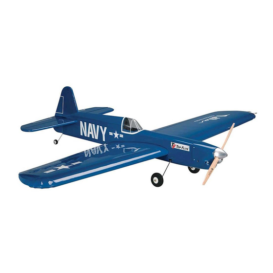
Wingspan: 50.5 in [1,285mm]
Wing Area: 500 sq in [32.2 dm
Weight: 42 – 50 oz [1,190 – 1,420g]
Wing Loading: 12 – 14 oz/sq ft
[37 – 43 g/dm
2
Length: 38.5 in [980mm] (tip of rudder
to tip of spinner)
Engine: .35 – .46 cu in [5.5 – 7.5cc]
2-stroke glow
WARRANTY.....
does not cover any component parts damaged by use or modification. In no case shall Top Flite's liability exceed the original cost of the purchased kit. Further, Top Flite
reserves the right to change or modify this warranty without notice. In that Top Flite has no control over the final assembly or material used for final assembly, no liability shall
be assumed nor accepted for any damage resulting from the use by the user of the final user-assembled product. By the act of using the user-assembled product, the user
accepts all resulting liability. If the buyer is not prepared to accept the liability associated with the use of this product, the buyer is advised to return this kit immediately
in new and unused condition to the place of purchase.
Top Flite Models
Champaign, IL
READ THROUGH THIS INSTRUCTION BOOK FIRST. IT CONTAINS IMPORTANT INSTRUCTIONS AND WARNINGS CONCERNING THE ASSEMBLY AND USE OF THIS MODEL.
Entire Contents © Copyright 2003
2
]
]
Top Flite
®
Models guarantees this kit to be free from defects in both material and workmanship at the date of purchase. This warranty
Telephone (217) 398-8970, Ext. 5
airsupport@top-flite.com
TOPZ9300 for TOPA1005 V1.0
Advertisement
Table of Contents

Subscribe to Our Youtube Channel
Related Manuals for Top Flite NOBLER ARF


Summary of Contents for Top Flite NOBLER ARF
- Page 1 In no case shall Top Flite’s liability exceed the original cost of the purchased kit. Further, Top Flite reserves the right to change or modify this warranty without notice. In that Top Flite has no control over the final assembly or material used for final assembly, no liability shall be assumed nor accepted for any damage resulting from the use by the user of the final user-assembled product.
-
Page 2: Table Of Contents
Aldrich in the 1950’s, the Nobler is now recognized 1. Your Top Flite Nobler ARF should not be considered Optional Supplies & Tools ....4... -
Page 3: Engine & Line Recommendations
ARF. Our test models performed superbly with finished model depends on how you build it; the O.S. ® MAX .40 LA-S and a Top Flite 11 x 4 Adhesives & Building Supplies therefore, we cannot in any way guarantee the Power Point ®... -
Page 4: Optional Supplies & Tools
Optional Supplies & Tools ORDERING REPLACEMENT PARTS The Top Flite Control Line Nobler ARF is factory covered with Top Flite MonoKote Sapphire blue These are some of the items used while building the Top Flite offers replacement parts for all of its film (6' [1.8m] roll–TOPQ0226). -
Page 5: Kit Contents
KIT CONTENTS PARTS PHOTOGRAPHED 1. Flaps 2. Wing 3. Horizontal Stabilizer with Elevators 4. Fuselage 5. Belly Pan 6. Vertical Stabilizer (Fin) with Rudder 7. Fiberglass Cowl 8. Canopy 9. Main Landing Gear (2) 10. 2-1/2" [65mm] Main Wheels (2) 11. -
Page 6: Important Building Notes
IMPORTANT BUILDING NOTES ASSEMBLE THE WING Hinge the Flaps • There are two types of screws used in this kit: Sheet metal screws are designated by a number and a length. For example #6 x 3/4" long [19mm] This is a number six screw that is 3/4" [19mm] long. 4. -
Page 7: Make The Flap Pushrod
blade to cut a small slit in the wing and flap on both sides of all the hinges. These slits will mark the ends of the hinge slots. 10. Without using any glue temporarily rejoin the flaps to the wing with the hinges. There should be little or no hinge gap and the flaps should move up and down freely. -
Page 8: Join The Flaps To The Wing
3. Test fit one of the metal clevises in the holes in Join the Flaps to the Wing both control horns on both joiner wires. If the clevis pins don’t go in, enlarge the holes in the joiner wires with a 1/16" [1.6mm] drill. Clean the joiner wires with denatured alcohol, and then thoroughly roughen them with coarse sandpaper so epoxy will adhere. -
Page 9: Finish The Wing
join the flap to the wing with the joiner wire. Wipe Finish the Wing away excess epoxy as it squeezes out. 6. Without using any glue, temporarily join the other flap to the wing and the joiner wire. This will align the joiner wire while the epoxy on the other side is hardening. -
Page 10: Assemble The Fuselage
Refer to this photo for the following two steps. 3. Remove the belly pan from the bottom of the 2. Separate the elevators from the stab by peeling fuselage. Temporarily bolt the wing to the fuselage off the tape. Use a pin to poke three or four holes with two 4-40 x 1-1/2"... - Page 11 5. Cut the covering from the fuselage over the 7. Now that the stab is level with the wing, center 9. Fold a piece of masking tape over the string slots for the stab and fin. the trailing edge of the stab in the fuselage by near the other end and draw an arrow on it.
-
Page 12: Make The Elevator Pushrod
down through the fuselage. Connect the clevis on the Make the Elevator Pushrod 4. Immediately after the solder has solidified, but pushrod to the middle hole in the flap control horn. while it is still hot, carefully use a cloth to quickly 1. -
Page 13: Join The Wing & Stab To The Fuselage
to the wing where it contacts the fuselage. Install the Join the Fin & Tail Wheel Refer to this photo for the following wing and bolt it into position. Use small balsa sticks two steps. and/or your paper towel squares to wipe up excess Refer to this photo for the following epoxy. -
Page 14: Mount The Main Landing Gear
2. Mount the wheels to the landing gear with a 1/8" Mount the Engine [3mm] wheel collar fastened by a 6-32 set screw on both sides. Add a drop of oil to both sides of the wheels so they spin freely. 5. -
Page 15: Mount The Cowl
2. Place the cowl on the fuselage and mount the 6. Remove the cowl screws and cowl. Add a spinner and propeller. Align the cowl with the spinner. couple of drops of thin CA to the screw holes–don’t There should be approximately 3/32" [2mm] between add too much CA, or you will seal the holes. - Page 16 9. Mount the needle valve and cut an access hole for it in the cowl. Note: On the model featured in this manual, the needle valve was mounted inverted. If mounting the needle sideways (as the engine is provided from the factory), a slot must be cut in the cowl to accommodate the needle valve body.
-
Page 17: Final Details
3. Position the decal on the model where desired. FINAL DETAILS Holding the decal down, use a paper towel to wipe away most of the water. Mount the Canopy 4. Use a piece of soft balsa or something similar to 1. -
Page 18: Wing Tip Weight
Use #2 We use a Top Flite Precision Magnetic Prop sheet metal screws, RTV silicone or epoxy to Balancer ™... -
Page 19: Control Check
Make all engine adjustments from behind the rotating CONTROL LINE Control Check propeller. 1. I will subject my complete control system (including safety thong, where applicable) to an With the lines connected to the leadouts and your The engine gets hot! Do not touch it during or right inspection and pull test prior to flying. -
Page 20: Flying
FLYING Preflight Flying Precautions Note: The Top Flite Nobler ARF is not a beginner’s For the first half-circle (during the brief period when model. It is intended for beginning to advanced stunt the pilot has the least control before the model is “up pilots who have had some previous control line to speed”) the wind will push the model outward to... -
Page 21: Takeoff
While the pilot is holding the lines, the assistant The pilot should be ready–especially during takeoff–to should walk the model once around the circle to be briefly step back to maintain line tension until the certain the flight path is clear and to double-check that model has gained enough air speed to achieve line there are no obstructions that could snag the lines. -
Page 22: Landing
when they become more experienced, wrist Clean the model using paper towels and household movement may be increased to increase control cleaner to wipe off exhaust residue. Inspect the response. All control inputs should be smooth. model thoroughly, looking for loose fasteners and Continue flying the model in a level attitude, getting signs of damage or fatigue. - Page 23 AMA STUNT MANEUVERS Here are some of the AMA Stunt Maneuvers. Refer to the AMA Rule Book for full descriptions. Consecutive Outside Square Loops Inverted Flight Takeoff Consecutive Inside Triangular Loops Consecutive Outside Loops Reverse Wingovers Consecutive Inside Loops Consecutive Inside Square Loops Horizontal Eights - 23 -...
-
Page 24: Flight Log
FLIGHT LOG DATE COMMENTS Started Construction Finished Construction First Flight First Loop First Inverted Flight First Wingover FLAP PUSHROD TEMPLATE...
Need help?
Do you have a question about the NOBLER ARF and is the answer not in the manual?
Questions and answers