Table of Contents
Advertisement
B53-0932-00
2 S ERVICE MANUAL
2012
WA022<Rev.001>
DDX3021, DDX3049, DDX3051, DDX319, DDX4021BT,
DDX4031, DDX4031BT, DDX4031BTM, DDX4031M,
Escutcheon
(B07-3263-02)
Screw set
(N99-1822-05)
* It uses it by some models. Refer to the parts list.
COPYRIGHT © 2012 JVC KENWOOD Corporation
B53-0932-00
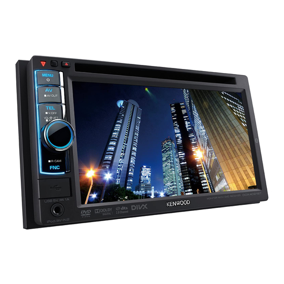
SERVICE MANUAL
MONITOR WITH DVD RECEIVER
DDX4049BT, DDX4051BT, DDX419
*
Escutcheon
(B07-3363-02)
*
Car cable (ST REMO)
(W01-2004-15)
COPYRIGHT © 2012 JVC KENWOOD Corporation
DC cord
(E30-8233-08)
Microphone
(W01-2009-08)
(3m)
*
Mounting hardware assy
(J22-0657-03)
*
Remote controller assy
(A70-2083-15)
RC-DV340
This product complies with the RoHS directive for the European market.
*
DC cord
(E30-8232-08)
*
Car cable (PRK)
(E30-8234-08)
*
Lever
(D10-7012-04) x2
*
Size AAA battery
(Not supplied)
This product uses Lead Free solder.
No.WA022<Rev.001>
*
*
*
PbF
2012/2
Advertisement
Table of Contents


Need help?
Do you have a question about the DDX3021 and is the answer not in the manual?
Questions and answers