Table of Contents
Advertisement
Advertisement
Table of Contents

Related Manuals for Smiths Medical CADD-Prizm PCS II


Summary of Contents for Smiths Medical CADD-Prizm PCS II
- Page 1 CADD-Prizm PCS II ® Ambulatory Infusion Pump Model 6101 Technical Manual...
-
Page 2: Table Of Contents
Table of Contents 1. Introduction ..........1 6. Safety Features and Fault Detection ..15 Limited Warranty ..........1 Hardware Safety Features ......15 Exposure to Radiation or Magnetic Resonance Watchdog Timer Circuit ......... 15 Imaging (MRI) ........... 1 Motor Driver/Motor Watchdog Circuit ... 15 Cassette ‘Type’ Sensor Circuit ....... 16 2. CADD‑Prizm PCS II Pump ...... 2 ® Latch/Lock Sensor Circuit ......16 Delivery Modes ..........2 Voltage Detector Circuit ......... 16 Specifications (Nominal) ........4 Software Safety Features ....... -
Page 3: Introduction
CADD-Prizm PCS II pump must be performed ® The best procedure to follow is to remove the by Smiths Medical or its authorized agents. pump from the patient during therapeutic The manufacturer’s warranty agreement shall radiation sessions or diagnostic levels of become null and void if the pump is not used radiographic and fluoroscopic radiation. -
Page 4: Cadd-Prizm ® Pcs Ii Pump
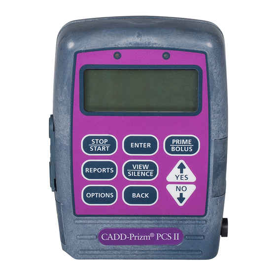
2 CADD-Prizm PCS II pump ® Delivery Modes PCA Delivery Profile The CADD‑Prizm PCS II pump provides The PCA (patient‑controlled analgesia) ® measured drug therapy to patients. delivery mode is used for therapies that CADD‑Prizm PCS II pumps are indicated for require a continuous rate of infusion, patient‑ ® controlled demand doses or both, such as intravenous, intra‑arterial, subcutaneous, intraperitoneal, epidural space or subarachnoid patient‑controlled analgesia. (See Figure 2.) space infusion. Epidural administration is limited to short‑term infusion of anesthetics and either long‑ or short‑term infusion of analgesics. Subarachnoid administration is limited to short‑term infusion of analgesics. (See Figure 1.) Indicator Lights Amber Green Polemount Display Bracket Recess Keypad ‹ ⁄ ¤ 2000-03-07 D. - Page 5 Continuous Rate Scroll Ranges Units Starting Increment Maximum Milliliters 0.10 0.10 30.00 Mg only Values between 0.01 and 0.5 Concentration Milligrams & 10% of 0.01 Micrograms concentration Mcg only Values between 0.1 and 0.5 0.1 x 30 Values between 0.5 and 100 Values between 100 and 1000 1.0 Values greater than 1000 10.0 Table 1. PCA delivery mode continuous rate scroll ranges. Milligrams Micrograms Concentration Demand Dose Clinician Bolus Concentration Demand Dose Clinician Bolus mg/ml increment max.
-
Page 6: Specifications (Nominal)
Specifications (Nominal) General Pump Specifications System Operating Temperature +2°C to 40°C (36°F to 104°F) Resolution System Storage Temperature CADD medication cassette reservoir ™ or CADD administration set, 0.050 ml ‑20°C to 60°C (‑4°F to 140°F) ® per pump stroke nominal Power Pack Charging Temperature Size +10°C to 35°C (50°F to 95°F) 4.4 cm x 10.4 cm x 14.1 cm [1.7 in x 4.1 in System DeliveryAccuracy x 5.6 in] excluding cassette or other accessories ± 6% (nominal) Weight System Definition 568 g [20 oz.] including 9 volt battery and empty System is defined as a CADD‑Prizm PCS II ® 100 ml CADD medication cassette reservoir, ™... - Page 7 Demand Dose Time 0 to 9.9 ml* 0000 to 2359 Delivery rate (Continuous Rate + Demand Air Detector Dose) programmable from 40 to 125 ml/hr. Turned On or Turned Off. Default: On Default: 0 ml (See Table 2, 3 & 4 for Scroll ranges) Biomed Toolbox Specifications *The Maximum Demand Dose is 20 with software revision E or higher. Custom Concentrations All individual mg or mcg concentration Demand Dose Lockout settings may be enabled or disabled (at least 5 minutes to 24 hours in the following one concentration must be enabled). increments: Default: All On • 1 minute for values between Program Limits* 1 and 20 minutes Maximum program limits may be • 5 minutes between 20 minutes programmed for Demand Dose, and 24 hours Continuous Rate, and Clinician Bolus. Default: 5 min Default: maximum program limits. Set Delivery Limit Dosing Limit* 0.5 ml to 1000 ml (or the mg or mcg Delivery Limit, a Maximum Doses per Hour, or...
- Page 8 Date Format Default:ing the Lock Level Code & US Standard (mm/dd/yy) or European Clinician Bolus Code Standard (dd/mm/yy). Default: U.S. Standard The standard Lock Level Code (061) can be Custom Main Display changed to a customized code using the Display: Biomed Toolbox Custom Lock Code feature. • Res Vol or Continuous Rate See the Operator’s Manual supplied with the • Power Source Always or Low 9 volt battery only pump for instructions on customizing the Lock Default: Res Vol and Low 9V Level Code. If it becomes necessary to change a customized code back to the standard Lock Auto Review* Level Code, do the following: Select the automatic program review feature 1. Press the OPTIONS key until the Lock Level during the pump’s power‑up sequence. screen appears Default: On 2. Press the ENTER key twice • Dose Counters (0 to 999 Given and/or 3. Scroll to 911 Attempted). Default: On 4. Press the OPTIONS key...
-
Page 9: Batteries
3 Batteries Battery Compatibility Recommended storage conditions are 10°C to 25°C (50°F to 77°F) with no more than 65% Recommended Batteries relative humidity noncondensing. Nine‑volt alkaline or lithium batteries are The following tables are based on laboratory recommended for use in the CADD‑Prizm ® tests conducted at room temperature using fresh PCS II pump. Carbon‑zinc, mercury, nickel‑ DURACELL alkaline batteries and a CADD ® ® cadmium, or zinc‑air 9‑volt batteries should administration set. Actual battery life will vary not be used. depending on the brand of battery, battery shelf life and temperature conditions. Battery Life The CADD‑Prizm PCS II pump has been ® ULTRALIFE Lithium Battery Life ® designed to provide optimal battery life. The expected battery life in the CADD‑Prizm PCS ® The following tables may be used to predict II pump depends on the following factors: typical lithium battery life at different delivery rates when a lithium battery is used in the • Programmed delivery rate... - Page 10 Continuous and PCA Delivery Battery Life (Max Delivery Rate PCA Mode 30 ml/hr) Note Results are without air detector. Rate Life Volume 0.4 ml/hr 120 hrs 48 ml 10 ml/hr 86 hrs 860 ml 30 ml/hr 37 hrs 1110 ml 50 ml/hr 26 hrs 1300 ml 100 ml/hr 13 hrs 1300 ml 200 ml/hr 14 hrs 2800 ml 350 ml/hr 7 hrs 2450 ml...
-
Page 11: Construction
4 Construction The pump’s housing is made of a special high The custom Liquid Crystal Display (LCD), also impact plastic designed to reduce interference located on the front housing, shows the pump from electromagnetic fields and to dissipate status and programmed settings. The dot matrix electrostatic discharge. It is composed of two display consists of 21 character columns with sections the base and cover housing. The pump 4 rows of characters, and is selected by the housing is sealed to ensure that the pump is pump’s microprocessor according to status water resistant. The battery compartment is not conditions and keyboard entries. water resistant. The microprocessor and other circuitry which control the pump are located on two printed NOTE circuit boards. The microprocessor board The CADD-Prizm PCS II ambulatory infusion ® contains the Central Processing Unit (CPU) and pump is water resistant, but not waterproof. its associated circuitry, motor driver circuitry, and other miscellaneous circuitry. The LCD The battery compartment is accessed through a board contains the Liquid Crystal Display with its removable door on the side of the base housing. -
Page 12: Theory Of Operation
5 Theory of Operation Keyboard Circuitry Time Base Circuitry The CADD‑Prizm PCS II pump is controlled An accurate 3.6864 MHz timebase is provided ® by a microprocessor. The actions of the by a quartz crystal. The 3.6864 MHz signal is microprocessor are controlled by a program, connected to the microprocessor, where it which is contained in the memory. is frequency‑divided to access the program memory at a cycle rate of 921 kHz. Commands are issued to the microprocessor from the user via the nine keys on the In addition, an accurate 32.768 kHz timebase is keyboard and the Remote Dose cord. The keys provided by a second quartz crystal. The 32.768 on the keyboard feed individually into the Gate kHz signal is used for the real time clock. Array on the microprocessor board. A key closure applies a ground to the associated LCD Circuitry input of the Gate Array. Key debounce The high‑impedance, low‑power, special circuitry resident in the Gate Array provides drive signals for the liquid crystal display are a clean output signal to the microprocessor provided by the LCD‑drivers. Each alpha or for the duration of the key closure. The numeric character on the LCD is formed by microprocessor reads keyboard status by darkening combinations of dots. Commands to accessing special memory locations in the display dots are issued via data bus commands... -
Page 13: Led Status Indicators
Flash PROM Technology to test the watchdog circuit on every power‑ up. By setting a flag in memory and not Program memory for the pump is stored in strobing the watchdog, the microprocessor Flash Programmable Read Only Memory can force a watchdog time‑out. After being (Flash PROM). This type of memory allows reset, the microprocessor checks the status modification of the contents without physically flag to see if this was a time‑out test. If so, removing the device from the circuit board. the microprocessor continues normal power‑ Under certain circumstances, the program up activities. If the reset occurred when the can also be downloaded through the I/O microprocessor was not expecting it, the port on the side of the pump. Several layers microprocessor traps the event, sounds the of redundancy in the programming system audible alarm and displays an error message prevent accidental erasing or modification of on the LCD. the PROM. Motor Driver/Motor Watchdog Circuit Gate Array Circuitry Motor drive circuitry is composed of a The Gate Array contains circuitry which series of power FET transistors, passive controls memory address decoding, components, and two voltage comparators. keyboard debounce, Light Emitting Diode Built into the motor drive circuitry is an RC (LED) indicator status, LCD command timer which times how long the motor runs buffering, Battery Backed RAM interface, and... -
Page 14: Power Circuitry
Power Circuitry Voltage Reference Circuit Power for the pump is normally supplied by a A voltage reference circuit provides a constant 9‑volt alkaline battery, 9‑volt lithium battery, DC voltage to the microprocessor Analog to or AC adapter. These types of batteries have Digital Converter (ADC). By reading this input a fairly low internal resistance over their and comparing the value to a predetermined discharge range, which will keep power supply range, the microprocessor can validate the noise low. Other types of batteries, such as accuracy of the 5‑volt power supply. Variations carbon‑zinc, exhibit high internal resistance, in the 5‑volt supply left undetected can result in especially near depletion. A voltage drop across inaccuracy in the low battery alarm set points the internal resistance occurs when current is and variations in other calculated values. drawn by the motor during pump activations. This current is demanded in short pulses when Voltage CADD Pump Status ® the motor is first turned on and generates large Trip Point* spikes in the battery voltage. This noise can >7.0V No alarm cause the low battery detection circuit to shut 6.4–7.0V* Transition to low battery down the pump. condition; battery low The motor driver circuit power is taken directly message appears; 3 beeps from the battery, but the microprocessor and its every 5 min. -
Page 15: Pumping Mechanism
Pumping Mechanism To deliver the amount of drug specified by the parameter settings, the pump’s microprocessor The pumping mechanism is linear peristaltic causes the pump mechanism to deliver 0.05 ml with two active valves. Pumping occurs when fluid “pulses” timed according to the desired the expulsor presses on the reservoir pump rate. At rates higher than 3 ml/hr, 2 pulses in tubing in sequence with the inlet and outlet succession will be given. Thus, to deliver 20 valves. At rest, the outlet valve is pressing down ml/hr, for example, the microprocessor solves fully on the tubing and the expulsor and inlet these equations: valve are retracted. (See Figure 7.) Mechanism activations per hr: When the microprocessor commands the mechanism to pump, the camshaft begins to = 20 ml per hr/0.1 ml per activation rotate, thus controlling the following pump cycle: = 20/0.1 1. The inlet valve closes. = 200 2. In synchrony with the expulsor moving down Time (seconds) between activations: to compress the tubing, the outlet valve opens, expelling 0.050 ml of fluid. = 3600 sec per hr/number of activations per hr 3. The outlet valve closes. = 3600/200 4. The inlet valve opens as the expulsor is = 18 retracted, causing fluid from the reservoir to... -
Page 16: Air Detector
Air Detector Theory of Operation The air detector is designed to detect air in The air detector consists of sensor electronics the outlet tubing fluid path. The air detector is and two ultrasonic transducers positioned on detachable if not needed. The CADD‑Prizm opposite sides of the tubing. One transducer ® PCS II pump automatically detects the presence acts as an acoustic transmitter and the other of the air detector and will automatically turn as an acoustic receiver. Air detection occurs the sensor on when powered up in LL0. when air in the fluid path causes a reduction in the signal level to the receiver. When the When the optional air detector is installed, the signal is interrupted for a preset length of Biomed Toolbox feature allows the air detector time, the sensing circuitry sends a signal to to be “required” or “not required.” When the air the microprocessor indicating air in the fluid detector is not required, it can be “turned on” or path. To maximize the reliability of the system “turned off” using the Options menu. When the and to reduce false alarms, the transmitted air detector is required, the option for turning signal is swept over a frequency range. This the air detector on or off will not be available. accommodates varying resonance frequencies When the air detector is turned on, the pump of the transducer and reduces sensitivity will detect the presence of air in the outlet to tubing tolerances and other mechanical tubing fluid path. If the air detector settings are variations. “not required” and “turned off,” it will Default: to “turned on” each time the pump powers up in Upstream Occlusion Sensor Lock Level 0. -
Page 17: Safety Features And Fault Detection
6 Safety Features and Fault Detection Hardware Safety Features flag to see if this was a time‑out test. If so, the microprocessor continues normal power‑ Key hardware safety features include a up activities. If the reset occurred when the watchdog timer circuit, motor driver and microprocessor was not expecting it, the motor watchdog circuits, cassette ‘type’ microprocessor traps the event, sounds the sensor circuit, latch/lock sensor circuit, and audible alarm and displays an error message a voltage detector circuit. Each safety circuit on the LCD. performs a unique function to insure the overall safety of the device. (See Figure 8.) Motor Driver/Motor Watchdog Circuit Watchdog Timer Circuit Motor drive circuitry is composed of a series of power FET transistors, passive The microprocessor must send an appropriate components, and two voltage comparators. signal to the watchdog circuit at least once Built into the motor drive circuitry is an RC per second. If the microprocessor does not, timer which times how long the motor runs the watchdog circuit will time out and shut each time it is turned on. If the motor runs down the pump controller. -
Page 18: Cassette 'Type' Sensor Circuit
Cassette ‘Type’ Sensor Circuit Voltage Detector Circuit The cassette ‘Type’ sensor system consists of Low voltage detection is performed by three pins protruding from the button of the part of the watchdog circuit and by the pump mechanism that interface to the attached microprocessor via software. Three low administration set and associated circuitry. voltage levels are detected. The first two Each type of administration set designed to levels are detected by software and the third work with the CADD‑Prizm PCS II pump by hardware. The first level to be reached is ® contains a unique ‘code’ programmed into the the Low Battery Warning threshold which set via nubs molded into the plastic. When a set occurs when the battery voltage decays is latched to the pump, the nubs press against to a nominal value of 6.8 volts. An Analog the pins in the pump mechanism in a pattern to Digital Converter (ADC) built into the unique to that set type. Optical detectors and microprocessor allows the microprocessor, electronic circuitry on the circuit board encode via software, to monitor the battery voltage. this pattern and report the information to the At the Low Battery Warning threshold, the microprocessor. This feature allows automatic microprocessor enables a periodic series rate selection dependent on the type of set of beeps and displays a low battery warning attached. This system also acts as a safety message on the LCD. As the battery voltage feature to detect a damaged or detached set. -
Page 19: Software Safety Features
Software Safety Features Hardware-related Software Data Handling Safety Features Software Safety Features Program Memory Check Data Stored in RAM At power up and at regular intervals Before use, data associated with delivery and thereafter, the program memory is tested stored in RAM is tested by calculating a CRC by calculating a Cyclic Redundancy Code on the data and then comparing it with the (CRC) on the program and then comparing it CRC stored with the data. If the stored and with the CRC stored with the program. If the calculated CRCs do not match, the software stored and calculated CRCs do not match, the will turn on a continuous two‑tone audible software will turn on a continuous two‑tone alarm and stop all drug delivery. audible alarm and stop all drug delivery. Data Stored in EEPROM RAM Memory Check Before use, data associated with delivery and At power up, the random access memory is stored in EEPROM is tested by calculating a... -
Page 20: Hardware And Software Fault Detection
7 Hardware and Software Fault Detection Overview Order of Error Code Events 1. There is a continuous two‑tone audible If the CADD‑Prizm PCS II pump displays an ® alarm, a continuous amber indicator light, error code, a hardware or software fault has and the display will read: been detected by the microprocessor, and the pump should be returned for servicing. When hardware or software faults are detected by the microprocessor, pump Error Detected operation stops and a continuous, audible alarm will be activated as well as the amber E(XXXXX) warning LED. An error message will be displayed. On the next power up, the error code will again be displayed with the software level (see illustration below). If the error NOTE detected was a data fault, the pump will be “XXXXX” is a 5-digit code. in Lock Level 2, and all other programmed 2. To silence the error code alarm, remove functions will have Default: values. (See the battery. -
Page 21: Cleaning And Inspection Procedures
All service and repair of CADD ® • Check the battery door for proper operation. pumps must be performed by Smiths Medical It should not be broken or damaged. The or its authorized agents. mating tabs on the pump housing should not be broken or damaged. Cleaning • Examine the battery compartment for CAUTION damage. If the battery contacts appear... -
Page 22: Testing Procedures
9 Testing Procedures Functional Testing If the Epidural mode is NOT turned on in the Options Menu The Power‑up Check, Latch/Lock Check Reservoir Latched VIEW to continue and Cassette Sensor Check using a CADD ™ medication cassette reservoir or CADD ® administration set can be performed with the pump in any of the four delivery modes. Admin set Latched Upstream Sensor On. Power-up Check VIEW to continue • Insert a battery in the pump and observe the LCD during power up. If the Epidural mode is turned on in the Options Menu Pump model number Error code... - Page 23 • Unlock the cassette. The display should • Reprogram the reservoir volume to 1.0 ml. show “Cassette Unlocked.” Unlatch the Press the VIEW/SILENCE key until Reservoir Administration Set. The display should Volume is displayed on the LCD. Press the show “Cassette Unlatched/Close Clamp To YES or NO key until 1.0 ml is displayed. Then Prevent Free Flow.” press the ENTER key. The following three checks (LCD, motor and NOTE gear train, and Reservoir Volume is Zero alarm) The remaining testing procedures should should be performed in the sequence shown. be performed using a 50- or 100-ml CADD ™ medication cassette reservoir containing fluid LCD Check and a primed extension set with anti-siphon • Remove and reinsert the battery. After a few valve or a primed CADD administration set...
-
Page 24: Air Detector Test (If Applicable)
Remote Dose Cord Check Air Detector Test (if applicable) • Check the Remote Dose Cord button This test will verify the function of the optional operation by programming the pump with air detector. To perform this test, the the following values: CADD‑Prizm PCS II pump must have an air ® Units Milligrams detector installed and the air detector must Concentration 1.0 mg/ml be turned on. The previous program from Continuous Rate 0.0 mg/hr the DOSE key check can be used to perform Demand Dose 1.0 mg this test. Demand Dose Lockout 0 hrs 5 min • Attach an empty CADD medication ™ Delivery Limit No Limit cassette reservoir or CADD administration ®... - Page 25 Downstream Occlusion Pressure Range • Pressure regulator, 30 psi Test (Option 1) • 50 or 100 ml CADD medication cassette ™ reservoir containing water Description Procedure Pressure is generated by activating the 1. Insert a battery and wait for the pump to pumping mechanism with an attached filled, power up. clamped CADD medication cassette reservoir. ™ 2. Attach a CADD medication cassette ™ The pump is started and a Demand Dose is reservoir to the pump. Latch and lock given until the high pressure alarm sounds. the cassette. Equipment needed NOTE 50‑ or 100‑ml CADD medication cassette ™ The pressure from the source must be zero reservoir containing water when the cassette is attached.
-
Page 26: Accuracy Testing
3. Program the pump to deliver a continuous Procedure rate of 30 ml/hr 1. Fill the 50‑ or 60‑ml syringe with 40 ml of 4. Start the pump water. Transfer the water into a CADD medication cassette reservoir. ™ 5. Clamp the tubing halfway between the fluid reservoir and the pump 2. Remove any air from the CADD Medication ™ Cassette reservoir by aspirating the air with 6. The pump should alarm within three the syringe. Attach the CADD extension set ® activations after clamping the tubing with anti‑siphon valve. Prime the tubing so it is filled with fluid to the end of the extension set NOTE luer lock connector. Make sure the upstream occlusion sensor is 3. Secure the clamp as close to the extension set turned on in the Biomed Toolbox. luer lock connector as possible. This should assure a minimum water loss from the tubing Accuracy Testing... - Page 27 EXAMPLE Procedure 1. Fill the 50‑ or 60‑ml syringe with 40 ml of Predelivery Weight 61.1 g water. Transfer the water into a Postdelivery Weight ‑ 41.6 g CADD medication cassette reservoir. ™ Weight of Amount Delivered 19.5 g 2. Remove any air from the CADD medication ™ = 19.5 ml cassette reservoir by aspirating the air with Volume of Amount Delivered 19.5 ml the syringe. Attach the CADD extension set ® Intended Delivery Volume ‑ 20.0 ml with anti‑siphon valve. Prime the tubing so it Inaccuracy Volume – 0.5 ml is filled with fluid to the end of the extension set luer lock connector. Inaccuracy Volume – 0.5 ml Intended Delivery Volume ÷ 20.0 ml 3. Attach the end of the extension set to the fluid collection device.
-
Page 28: Cleaning And Functional Testing Checklist
CADD-Prizm PCS II pump Cleaning and Functional Testing Checklist ® The following checklist is provided as a guide only to assist in establishing documentation of cleaning and functional testing for the CADD‑Prizm PCS II pump. If service is provided, fill out ® this sheet and return it with the device. Serial # _______________ Reference Number _______________________ Date _______________________ (Refer to the Technical Manual procedures.) I. Cleaning Completed Yes No II. Visual Inspection LCD Lock Data In/Out Jack Occlusion Sensor Seals Cassette Sensors (3) Air Detector or Port Cover Valves and Expulsors Keyboard Pump Housing Reservoir Hinge Area... - Page 29 Smiths Medical ASD, Inc. Smiths Medical Canada Ltd. EC Authorized Representative Smiths Medical International Ltd. St. Paul, MN 55112, USA Markham, Ontario, Canada, L3R 4Y8 TN25 4BF, UK Phone 1‑214‑618‑0218 Phone 905‑477‑2000 Phone +44 (0) 1233 722100 Toll‑Free USA 1‑800‑258‑5361 Toll‑Free 1‑800‑387‑4346 www.smiths‑medical.com Smiths Medical is part of the global technology business Smiths Group plc. Product(s) described may not be licensed or available for sale in Canada or other countries outside of the United States. CADD, CADD‑Prizm and the Smiths Medical and CADD design marks are trademarks of Smiths Medical. The symbol ® indicates the trademark is registered in the U.S. Patent and Trademark Office and certain other countries. ©2010 Smiths Medical. All rights reserved. 11t/10 IN19779...
Need help?
Do you have a question about the CADD-Prizm PCS II and is the answer not in the manual?
Questions and answers