
Related Manuals for Adtec EN-30


Summary of Contents for Adtec EN-30
-
Page 1: User Guide
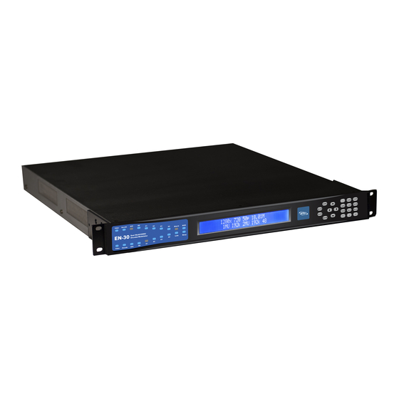
EN-30 Dual Channel Capable HD/SD MultiCODEC DSNG Encoder w/ optional IF/LB/10Mhz Modulation USER GUIDE 2.01.10... - Page 2 Table of Contents Table of Contents Trademarks & Copyrights Electrical Device Compliance Notices Safety Warnings and Cautions Compliance Notices Industry Canada European Union EMC Directive Conformance Statement Chapter 1 - Product Overview Product Introduction Chapter 2 - Getting Started Front Panel Panel Diagram Model Indicator Decals Front Panel LCD Quick Views...
- Page 3 EN30-MP2-01 Video Specs (MPEG2): EN30-MP4-01 Video Specs (AVC): IF, L-Band Modulator + 10MHz (option) - IF/LB/10M-01 Appendix C - DB9-M Analog audio input pinout Appendix D - Adtec Digital Support & Service Telephone and Email Support Preparing for Support SLA Options...
- Page 4 Trademarks & Copyrights Copyright: ( c) 2012-Present: Adtec Digital. All rights reserved. This document may not, in whole or in part, be copied, photocopied, reproduced and translated, or reduced to any electronic medium or machine-readable form without prior written consent from Adtec Digital.
- Page 5 Electrical Device Compliance Notices Safety Warnings and Cautions For your safety and the proper operation of the device: ● This unit must be installed and serviced by suitably qualified personnel only. ● Do not break the warranty seals on the device or open the lid. Only approved service technicians are permitted to service this equipment.
-
Page 6: Industry Canada
● Consult the dealer or an experienced radio/TV technician for help. Warning: C hanges or modifications to this device not expressly approved by Adtec Digital could void the user’s authority to operate the equipment. Industry Canada This Class B digital apparatus meets all requirements of the Canadian Interference Causing Equipment Regulations. - Page 7 The EN30 can be ordered with optional satellite modulation for contribution and distribution applications. It inherits Adtec’s broadcast quality compression, advanced feature set, service performance, and reliability in the new dense two-channel platform targeted towards broadcasters, cable and IP compression applications.
- Page 8 Chapter 2 - Getting Started Front Panel The Function Buttons and Directional Keypad of the EN-30 are used to configure and monitor the signal input and output of the device. Panel Diagram Model Indicator Decals Front Panel LCD Quick Views There are 9* Quick Views that can be accessed by the front panel LCD by pressing the up and down arrows.
- Page 9 3) V ideo Input State: This quick view displays the resolution, input signal source, and input signal mode for both encoder modules. 4) V ideo Encoding State: T his quick view displays the Video Bit Rate, CODEC, and Chroma type for both encoder modules.
- Page 10 8) ASI Remux State: This quick view displays the status of ASI Remux status if the feature is enabled. 9) *Modulator State: This quick view displays the status of RF Tx status if the unit is equipped with optional modulator. Transport LED Indicators - Channel 1 &...
- Page 11 System Indicators Indicator Function Alarm Off - No system alarms. On - System alarm. (Typically NTP alarm) BISS Off - No encryption set On - Encryption active Link Off - No network detected On - Network communication active Busy Off - No network activity On - Network traffic present Controls Using the Mode, Select, Enter, Escape, and directional buttons, the user can control the unit...
- Page 12 Modulator Lineup This feature enables the operator to quickly view and/or configure select modulator RF output parameters. The parameters available in this menu are; 1. Carrier Mode: [ PURE_CARRIER or MODULATED] 2. Transmit: [ ENABLED or DISABLED] 3. Output Power: [ in 0.5dB increments ] 4.
- Page 13 Front Panel Menu Structure Services Menu The following diagram illustrates the structure and flow of the S ervices Menu on the Adtec EN-30 device. TX MUX Rate, Table, and TSID are global configurations, while items under the denoted << >> parallel menu are unique to each encoder :...
- Page 14 Service 1 - 65535 The Service Number or Program Number in PAT & PMT packets identifies which program Number is associated with which Video & Audio PIDs. This value should be entered in decimal format Logical This setting allows you to set the logical 1 - 9999 *.ECMD# LCN Channel...
- Page 15 RF Tx Menu The following diagram illustrates the structure and flow of the R F Tx Menu on the Adtec EN-30 device. This menu will not be available on units without the optional RF modulators. Item Function Options Transmit...
- Page 16 8PSK-5/6 32APSK-7/9 8PSK-8/9 32APSK 2/3 8PSK-9/10 64APSK-32/45-L 8PSK-23/36 64APSK-11/15 8PSK-25/36 64APSK-7/9 8PSK-13/18 64APSK-4/5 8PSK-7/15 64APSK-5/6 8PSK-8/15 128APSK-3/4 8PSK-26/45 128APSK-7/9 8PSK-32/45 256APSK-29/45-L 16QAM-3/4 256APSK-2/3-L 16QAM-7/8 256APSK-31/45-L 16APSK-2/3 256APSK-32/45 16APSK-3/4 256APSK-11/15-L 16APSK-4/5 256APSK-3/4 Local Determines the Local Oscillator User defined Oscillator Frequency (in Mhz) variable in the embedded Uplink Calculator.
- Page 17 ** The monitor output frequency for the EN-XX IF is fixed at 1.080GHz. The monitor output frequency for the EN-XX L-Band tracks with the main RF output frequency. Power Allows the operator to configure the 7039: -50 to -7dBm LBAND output power of the main RF output 7139: -35 to +5dBm LBAND port.
- Page 18 approximately 3.0%. Rate Priority The Rate Priority control allows the Symbol operator to designate which rate will Interface be kept constant. When the Symbol Rate is entered and Rate Priority is Symbol, the symbol rate is held constant and the Interface rate is calculated.
- Page 19 MODULATOR This feature enables the operator to Carrier Mode: LINEUP quickly view and/or configure select PURE_CARRIER or MODULATED modulator RF output parameters. Transmit: ENABLED or DISABLED Output Power: User defined in 0.5dB incr. Uplink Frequency: User defined in 1.0MHz incr.
- Page 20 IP Tx Menu The following diagram represents the structure of the I P Tx Menu Menu: Control Function Options API Command Mode switches multicast function on *.ECMD0 MMO and off Send Tx IP Address The IP Address of which the user-defined;...
- Page 21 the network should make Minimize Cost negotiate queuing between Maximize throughput, delay, reliability, and Reliability cost. Maximize Throughput Minimize Delay Time to live is a numeric value 1 - 255 *.ECMD0 TTL # from 1 to 255 that specifies the number of iterations or transmissions the packet can undergo before it is discarded.
- Page 22 Video Menu The following diagram illustrates the structure and flow of the V ideo Menu on the Adtec EN-30 device: Control Function Options API Command Input Video Input designates the type of *.ECMD# INP video signal being received, either COMPOSITE SDI or Composite.
- Page 23 H.264 (MP4): 2 - 30 Mb/s Aspect Ratio Aspect Ratio can be set to 16x9 or 16x9 *.ECMD# ARA 4x3 when the input is a SD resolution Active Format Descriptor is data *.ECMD# AFD that can be sent in a MPEG video View AFD API stream that provides information 2 - 11...
- Page 24 Audio Menu The following diagram illustrates the structure and flow of the A udio Menu on the Adtec EN-30 device: Control Function Options API Command << 1 - 2 >> Parallel Menus. Surround Determines the surround sound OFF, DD, DD-06, *.ECMD# SMO 0...
- Page 25 offset. The valid range is +/- 800 milliseconds. Non functional for Musicam Encode Format Determines the format of the STEREO *.ECMD# MCM ( 0-3) audio CODEC MONO DUALMONO This is a low latency audio path *.ECMD# AIF (0-3) for communications to a remote van or studio using the same GHOST distribution path.
- Page 26 PIDs Menu The following diagram illustrates the structure and flow of the P IDs Menu on the Adtec EN-30 device: Control Function Options API Command PMT PID Configures PID marked for Hex value 0x0020 - *.ECMD# PPI the PMT...
- Page 27 VBI Menu The following diagram illustrates the structure and flow of the V BI Menu o n the Adtec EN-30 device: Control Function Options API Command VBI Source VBI Source allows selection of *.ECMD# VBS Composite or SDI for as vbi data source.
- Page 28 Profile Menu The following diagram illustrates the structure and flow of the P rofile Menu on the Adtec EN-30 device: Control Function API Command Select Select a previously saved profile to RUN / LOAD as *.SYSD PROFILE the current configuration. Press <select>, then use up/down arrows to browse through available profile names.
- Page 29 CAS Menu The following diagram illustrates the structure and flow of the C AS Menu on the Adtec EN-30 device: Control Function Options API Command Channel 1 Turns Service 1 *.ECMD0 ECR Encryption ON/OFF Channel 2 Turns Service 2 *.ECMD1 ECR...
- Page 30 System Menu The following diagram illustrates the structure and flow of the S ystem Menu on the Adtec EN-30 device: Login Units ship with the front panel logged in by default. If you become logged out and are prompted for a password, use the following key sequence for access.
- Page 31 Backlight Dim Delay Action Press <Select> Using the <Up> and <Down> arrows, select the value you wish. Press <Enter> to save your selection Network Sub Menu Item Function Options Ethernet IP Address This is the address of your device user-defined using the numeric on your network specific to the keypad Ethernet Port.
- Page 32 Controls the status (ON/OFF) of the Simple Network Management Protocol (SNMP) CLEAR feature. We support SNMPv2c version. Read-only The Simple Network user-defined community Management Protocol (SNMP) Read-Only Password. Default Value: "adtec" Read-write The Simple Network user-defined community Management Protocol (SNMP) Read-Write Password. Default...
- Page 33 Value: "none" Trap The Simple Network user-defined community Management Protocol (SNMP) trap community. Default Value: "public" Trap sink The Simple Network Enter the IP address of your SNMP trap Management Protocol (SNMP) sink server. trap sink. Default Value: "127.0.0.1" Com2 Item Function Options...
- Page 34 Firmware Item Function Options Firmware Displays the currently running Read-Only firmware version...
- Page 35 Back Panel Diagram Processor Connectors Connection Function AC Power AC Power- standard 3-pin plug (70-240 VAC 50-60 Hz), 5VDC Power (x2) - External Power Only GigE GigE Interface- TS Output over RTP/UDP COM2 API Serial Communication Interface COM1 Serial Port used for Troubleshooting Ethernet 10/100BASE-T - Ethernet interface DVC Parport...
- Page 36 HD/SD-SDI Input 2 BNC 75 Ohm Input CVBS Composite Input 2 BNC 75 Ohm Input Analog Audio Input 2 EAS Video In RCA 75 Ohm EAS Video Loop Out RCA 75 Ohm EAS Audio In Vertical single RCA jack EAS Audio Loop Out Vertical single RCA jack ASI Input BNC 75 Ohm...
- Page 37 Access the application by pointing your web browser to the unit's IP address. Log in to the application by clicking the " Proceed to Login" button and typing in the user name ' adtec' and the password ' none' in the pop-up box that appears.
- Page 38 The application has two operating windows, the S tatus Window and the M ain Window : Status Window: The Status Window is fixed on the left-hand side of the screen- it will display regardless of what function is being displayed in the Main Window. The current status parameters of the unit's are always in view and are updated in real time.
- Page 39 You can upgrade your Adtec device's firmware via built-in web-based application, described in the U pgrade Tab section, or via a Telnet/FTP session, described in this article. To update your Adtec device 's firmware via a Telnet session, perform the following: Manual Upgrade Process Step Action Obtain the desired firmware version file from www.adtecftp.com...
- Page 40 When prompted for a username, enter adtec. When prompted for a password, enter none. Once you see "User 'adtec' connected", the session is open and you may issue API commands to the unit. For the EN-30 device, there are specific commands for the modulator, encoder, and the unit's operating system.
- Page 41 Note that firmware and profile loading is one click easy through the web user interface. How to Use API Commands The Adtec EN-30 device is unique in that it handles two physical encoders. To accommodate commands for controlling both encoders, you will need to specify which encoder you are working with for each command you issue.
- Page 42 How Video Rates are Configured (Example is pertinent to MPEG2 (MP2)) Video rates can be configured manually or automatically. The factory default is to automatically set the video rate based on TMR. This option is referred to as VAF (Video Autofill). VAF determines what the TMR is.
- Page 43 GO button. To disable EAS mode press the large STOP button. How to configure Network EAS Triggering By default, the EN-30 is configured to send an EAS trigger over the local network to all Adtec dual channel encoders (HDMI2QAM, YUV2QAM, EN-20 or EN-30). This feature can be disabled by unchecking the box next to “Network EAS Triggering”, then pressing the apply...
- Page 44 How passthru audio functions - Dolby E / 5.1 / 2.0, Dolby D, LPCM The Adtec EN-30 encoder supports four pairs of audio encoding or two pairs of passthru per service. An audio passthru consists of a compressed bitstream ( Dolby E 20 Bit / Dolby E 16 Bit / Dolby Digital / Linear Acoustic Stream Stacker 2 ) or an uncompressed stereo pair ( LPCM ) from embedded SDI passed into the egress transport stream ( IP, *RF, ASI ).
- Page 45 not being presented on the corresponding input. The SDI matrix can be changed to each pair without restarting the encode session. Once hash is heard, then a compressed bitstream should be present. Set the mode back to Passthru for the automatic detection mechanism to configure the Dolby type and bitrate.
- Page 46 ○ Even if Service 2 is set to OFF, Service 1 can still only allocate 50% of the Audio resources Encoding: The EN-30 has the following Audio Encoding capabilities and resources. Different CODECs require a different amount of resources. The EN-30 has logic built-in so that the user cannot exceed the audio resources. CODEC MODE...
- Page 47 The important thing is to be aware of different configurations and how resource intensive they are. If an EN-30 is not accepting the settings being submitted, then check the other pairs of audio and ensure the threshold is not being exceeded.
- Page 48 How to use ASI Remux Terminology: “ASI Remux” refers to the ability for an Adtec EN to accept a Transport Stream (TS) via ASI input, and multiplex the incoming service or services with it’s locally encoded service. The result is that the transport stream output becomes a MPTS containing the services from the ASI input in addition to the locally encoded service.
- Page 49 PMT - Program Map Table. This MPEG-2 table specifies PID values for components of programs. The Adtec EN-3X and EN-100 encoders have an ASI input available for the ASI remux feature. Further information can be read about ASI Remux in the ASI Remux article. In some cases, users may want to add custom PID’s from third party generators, such as a DVB Subtitles, into...
- Page 50 As EN encoders do not perform PID conflict resolution at this time, the PID’s inserted into the system should not conflict with other PID’s utilized by the EN-30. To configure ASI Passthrough of DVB subtitles, visit the Manual PIDs tab. This tab contains PMT template entries that will be used to insert into the PMT.
- Page 51 The user will then need to map the entry into the associated PMT by visiting the Manual PID Mapping tab. The Italian DVB Subtitle PID was entered into the first manual PID configuration. This can be mapped by moving the associated PID from the ‘Unmapped PIDs’ box into the ‘Mapped PIDs’...
- Page 52 MPEG1_Layer2 MPEG2_Part3 ISO_IEC_13818_PRIVATE ISO_IEC_13818_PES_PRIVATE DVB_AC3_AUDIO ISO_IEC_13522_MHEG DSM_CC ITU_T_REC_H222_1 ISO_IEC_13818_6_Type_A ISO_IEC_13818_6_Type_B ISO_IEC_13818_6_Type_C ISO_IEC_13818_6_Type_D ISO_IEC_13818_1_Aux ISO_IEC_13818_7_AUDIO_ADTS H264_VIDEO AVC_VIDEO DCII_VIDEO DOLBY_AC3 DCII_SUBTITLES DVB Specification for Service Information (SI) in DVB systems. Descriptor information can be reviewed here. https://www.dvb.org/resources/public/standards/a38_dvb-si_specification.pdf...
- Page 53 Vertical Interval Time Code Vertical Interval Time Code (VITC) is typically used in transmissions that require time code from the originating source to be preserved. It was originally developed for analog television recording systems, but has new standards for transmitting in digital systems (SMPTE-12M-1 / SMPTE-12M-2).
- Page 54 Chapter 5 - Appendix Appendix A - GNU General Public License Version 2, June 1991 Copyright (C) 1989, 1991 Free Software Foundation, Inc. 59 Temple Place, Suite 330, Boston, MA 02111-1307 USA Everyone is permitted to copy and distribute verbatim copies of this license document, but changing it is not allowed.
- Page 55 The "Program", below, refers to any such program or work, and a "work based on the Program" means either the Program or any derivative work under copyright law: that is to say, a work containing the Program or a portion of it, either verbatim or with modifications and/or translated into another language.
- Page 56 a) Accompany it with the complete corresponding machine-readable source code, which must be distributed under the terms of Sections 1 and 2 above on a medium customarily used for software interchange; or, b) Accompany it with a written offer, valid for at least three years, to give any third party, for a charge no more than your cost of physically performing source distribution, a complete machine-readable copy of the corresponding source code, to be distributed under the terms of Sections 1 and 2 above on a medium customarily used for software interchange;...
- Page 57 section is held invalid or unenforceable under any particular circumstance, the balance of the section is intended to apply and the section as a whole is intended to apply in other circumstances. It is not the purpose of this section to induce you to infringe any patents or other property right claims or to contest validity of any such claims;...
- Page 58 POSSIBILITY OF SUCH DAMAGES. END OF TERMS AND CONDITIONS How to Apply These Terms to Your New Programs If you develop a new program, and you want it to be of the greatest possible use to the public, the best way to achieve this is to make it free software which everyone can redistribute and change under these terms.
- Page 59 Appendix B - Technical Specifications EN30-MP2-01 Video Specs (MPEG2): Encoder Video Profiles MPEG 2 SD Profile 1: Adaptive Field Frame (AFF) ISO13818-2 MP@ML MPEG 2 SD Profile 2: AFF ISO13818-2 422P@ML MPEG 2 HD Profile 1: ISO13818-2 MP@HL (1920/1440x1080 or 1280 x 720) Video Encoding Data Rates (Manual) MPEG 2 MP@ML SD: 1 Mb/s - 15 Mb/s (NTSC and PAL) MPEG 2 422P@ML SD: 1 Mb/s - 50 Mb/s (NTSC and PAL)
- Page 60 Interface: SD/HD-SDI Auto frame rate and resolution detection SD-SDI (SMPTE 259M - 270 Mb/s) with embedded audio per SMPTE 272M HD-SDI (SMPTE 272M - 1.485 Gb/s) with embedded audio per SMPTE 299M Connector: BNC 75 Ohm Interface: SD Composite (CVBS) A nalog Composite NTSC and PAL Audio Input: Connector/Interface:...
-
Page 61: Conditional Access
Connector: RCA jack 75Ohm Interface: Terminated NTSC or PAL D1 Composite Input with loop EAS Audio: Connector: Vertical single RCA jack Interface: mono audio channel with loop EAS Triggering Interface: Web UI Conditional Access: BISS 1/E Transport Outputs: All outputs operate concurrently. Connector: BNC x2 ISO13818-1 MPEG 2 Transport Stream per EN 50083-9:1997 (188 byte only). - Page 62 Specifications Disclaimer: Specifications subject to change without written notice. Copyright 2013 Adtec Digital. EN-30 is a trademark of Adtec Digital. Other product and company names may be trademarks or registered trademarks of their respective companies. This information may not, in whole or in part, be copied, photocopied, reproduced and translated, or reduced to any electronic medium or machine-readable form without prior consent in writing from Adtec Digital.
- Page 63 Appendix C - DB9-M Analog audio input pinout Signal Left + (Audio 1) Left - (Audio 1) Ground Right - (Audio 1) Right + (Audio 1) Left + (Audio 2) Left - (Audio 2) Right - (Audio 2) Right + (Audio 2)
- Page 64 All inquiries will be processed in the order in which they are received and by the criteria outlined in the Call Response Order. Inquiries and inquiry responses made after 5:00 PM (CST) weekdays, Saturday, Sunday or on an Adtec-recognized holiday will be processed the next business day in the order received.
- Page 65 Include the approximate time and day the problem occurred, the spot ID of the material being inserted and what the operator reported about the incident. It is also helpful to note any recent changes to the system. More information is always better than too little information.
- Page 66 ** Excludes equipment that has been subject to misuse, negligence, or accident All SLAs are subject to terms and conditions of Sale and Support. For details, see Adtec Digital Terms of Sale of Sale and Adtec Digital Terms of Standard Limited Support...
Need help?
Do you have a question about the EN-30 and is the answer not in the manual?
Questions and answers