
Related Manuals for Firepower FP 125


Summary of Contents for Firepower FP 125
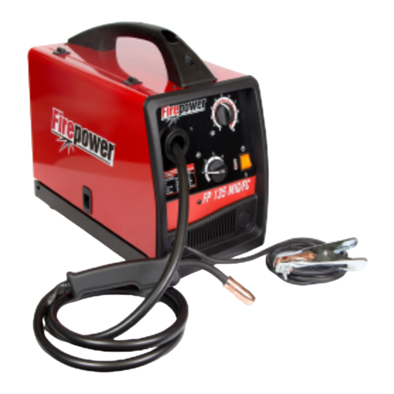
- Page 1 Firepower ® FP 125, FP 135, FP165 PORTABLE MIG/FLUX CORED WELDER Operating Manual Révision : AC Issue Date: April 6, 2016 Manual No.: 0-5123 www.firepoweronline.com...
- Page 2 WE APPRECIATE YOUR BUSINESS! Congratulations on your new Firepower product. We are proud to have you as our customer and will strive to provide you with the best service and reliability in the industry. This product is backed by our extensive warranty and world-wide service network.
- Page 3 While the information contained in this Manual represents the Manufacturer's best judgement, the Manufacturer assumes no liability for its use. Firepower FP 125, 135, 165 MIG/Flux Cored Welder Operating Manual Number 0-5123 Published by: ESAB 2800 Airport Rd.
- Page 4 Be sure this information reaches the operator. You can get extra copies through your supplier. CAUTION These INSTRUCTIONS are for experienced operators. If you are not fully familiar with the principles of operation and safe practices for arc welding and cutting equip- ment, we urge you to read our booklet, “Precautions and Safe Practices for Arc Welding, Cutting, and Gouging,”...
-
Page 5: Table Of Contents
Establishing the Arc and Making Weld Beads ..........4-7 4.10 Pre-Weld Procedure ..................4-7 4.11 Welding Procedure ..................4-7 4.12 Reference Tables .................... 4-8 4.13 Firepower FP 125 Welding Setting Selection Guide ........4-9 4.14 Firepower FP 135 Welding Setting Selection Guide ........4-10... - Page 6 TABLE OF CONTENTS 4.15 Firepower FP 165 Welding Setting Selection Guide ........4-11 4.16 Gas Selection for Gas Metal Arc Welding ............4-12 SECTION 5: SERVICE ....................5-1 5.01 Cleaning of the Unit ..................5-1 5.02 Cleaning of the Feed Rolls ................5-1 5.03...
-
Page 7: Section 1: Safety
FIREPOWER FP 125,135,165 SECTION 1: SAFETY Safety Precautions Users of ESAB welding and plasma cutting equipment have the ultimate responsibility for ensuring that anyone who works on or near the equipment observes all the relevant safety precautions. Safety precautions must meet the requirements that apply to this type of welding or plasma cutting equipment. - Page 8 FIREPOWER FP 125,135,165 Arc welding and cutting can be injurious to yourself and others. Take WARNING precautions when welding and cutting. Ask for your employer's safety practices which should be based on manufacturers' hazard data. ELECTRIC SHOCK - Can kill.
-
Page 9: Précautions De Sécurité
FIREPOWER FP 125,135,165 Précautions de sécurité Les utilisateurs du matériel de soudage et de coupage plasma ESAB ont la responsabilité ultime d'assurer que toute personne qui opère ou qui se trouve dans l'aire de travail observe les précautions de sécurité pertinentes. Les précautions de sécurité doivent répon- dre aux exigences applicables à... - Page 10 FIREPOWER FP 125,135,165 LE SOUDAGE ET LE COUPAGE À L'ARC PEUVENT CAUSER DES BLESSURES À L'OPÉRATEUR OU LES AUTRES PERSONNES SE TROUVANT DANS L'AIRE DE TRAVAIL. ASSUREZ-VOUS DE AVERTISSEMENT PRENDRE TOUTES LES PRÉCAUTIONS NÉCESSAIRES LORS D'UNE OPÉRATION DE SOUDAGE OU DE COUPAGE. DEMANDEZ À...
-
Page 11: Introduction
2. FCAW – Flux-cored arc welding – Does not require the Electronic copies of this manual can also be downloaded at no use of a shielding gas. charge in Acrobat PDF format by going to the Firepower web site listed below http://www.firepoweronline.com... -
Page 12: Specifications
(Based on Article 630, National Electrical Code) Firepower continuously strives to produce the best product possible and therefore reserves the right to change, improve or revise the specifications or design of this or any product without prior notice. Such updates or changes do not entitle the buyer of equipment previously sold or shipped to the corresponding changes, updates, improvements or replacement of such items. -
Page 13: Volt - Amp Curves
Art # A-09076_AB 35.0 30.0 25.0 20.0 15.0 10.0 OUTPUT CURRENT Figure 2-1: Volt/Amp curves of the Firepower 125 FP 135 FIREPOWER Vin=115V 60Hz Art # A-09077_AB OUTPUT CURRENT Figure 2-1: Volt/Amp curves of the Firepower 135 Manual 0-5123 INTRODUCTION... - Page 14 FIREPOWER FP 125,135,165 FP 165 FIREPOWER Vin=230V 60Hz Art # A-09078_AB OUTPUT CURRENT Figure 2-1: Volt/Amp curves of the Firepower 165 INTRODUCTION Manual 0-5123...
-
Page 15: Duty Cycle
117 amps, for 2 minutes out of every 10 minute period. Dur- ing the other 8 minutes of the 10 minute period, the Firepower FP 135 must idle and be allowed to cool. The thermal cutout will operate if the duty cycle is exceeded. -
Page 16: Mig Gun Maintenance
FIREPOWER FP 125,135,165 2.08 MIG Gun Maintenance Remove dust and metallic particles from the gun conduit by forcing clean, dry compressed air into the conduit once a week. This will minimize wire feeding problems. 2.09 Handle / Feet Assembly Art # A-09094... -
Page 17: Installation
In order to obtain the maximum output capability of the Firepow- receptacle. er FP 125 a branch circuit capable of 40 amperes at 115 to 125 Except for some early models, the Firepower FP 165's power Volts 60 Hz is required. In order to obtain the maximum output... -
Page 18: Installation Of Shielding Gas (Gmaw) Process
FIREPOWER FP 125,135,165 3.06 Installation of Shielding Gas (GMAW) Process Refer to Figure 3-1. NOTE! Shielding Gas is not required if the unit is using self-shielded FCAW (flux cored arc welding) wires. 1. Cylinder Positioning: Chain the cylinder to a wall or other support to prevent the cylinder from falling over. If an optional por- table mounting arrangement is used, follow the instructions that are provided with it. - Page 19 FIREPOWER FP 125,135,165 Shielding Regulator and Flow Meter “Cracking” Shielding Shielding Shielding Art # A-07965 Gas Hose Figure 3-1 Gas Cylinder Installation for Reference Only! Manual 0-5123 INSTALLATION...
- Page 20 FIREPOWER FP 125,135,165 Adjusting Regulator Adjust control knob of regulator to the required flow rate, indicated on gauge dial. (Refer to Figure 3-2 and data charts. Approx. 20 CFH) The gas flow rate should be adequate to cover the weld zone to stop weld porosity. Excessive gas flow rates may cause turbulence and weld porosity.
-
Page 21: Attaching The Gun And Cable Assembly To The Power Source
3.07 Attaching the Gun and Cable Assembly to the Power Source The Firepower FP 125, FP 135, FP 165 are supplied with a 80A MIG gun. The 80A MIG gun is designed with an ergonomic handle and fewer parts to eliminate performance problems. The 80A MIG gun uses standard readily available Firepower consumable parts. -
Page 22: Polarity Changeover
FIREPOWER FP 125,135,165 3.08 Polarity Changeover WARNING ELECTRIC SHOCK CAN KILL! Make certain the machine is unplugged from the power receptacle. Do not plug machine in until told to do so in these instructions As delivered from the factory, the output polarity is set to the polarity which matches the welding wire supplied with the unit. The output terminals are located on the interior panel of the welding power source if you need to change polarity. -
Page 23: Installing Wire Spool
FIREPOWER FP 125,135,165 3.09 Installing Wire Spool 3.10 Feedrolls As delivered from the factory, the unit is set for an 4” (102mm) A feedroll consists of two different sized grooves, .023” (0.6mm) spool. and .030” / .035” (0.8mm / 0.9mm). - Page 24 FIREPOWER FP 125,135,165 Pressure Arm Pressure Adjust Device Pressure Arm Pressure Adjust Device Gun Cable End Gun Cable End Wire Art # A-09083 Wire Spool Inlet Wire Guide Feedroll Art # A-09085 Spool Wire Guide Feedroll Figure 3-10: Inserting Wire...
-
Page 25: Install Wire Into The Welding Gun
Wire Feed 1. Plug the Welding Power Source into the 120VAC recep- Speed tacle for the Firepower FP 125 and FP 135, and into the 230VAC receptacle for the Firepower FP 165. WARNING ELECTRIC SHOCK CAN KILL! With the gun... - Page 26 FIREPOWER FP 125,135,165 This Page Intentionally Blank INSTALLATION 3-10 Manual 0-5123...
-
Page 27: Operation
FIREPOWER FP 125,135,165 SECTION 4: OPERATION 4.01 General Safety Precautions Read and understand the safety instructions at the beginning of this manual prior to operating this machine. WARNING Be sure to put on proper protective clothing and eye safeguards (welding coat, apron, gloves, and welding helmet, with proper lenses installed). - Page 28 Excessive tension on the brake will cause rapid wear of mechanical wire feed parts, overheating of electri- cal components and possibly an increased incidence of wire burnback into the contact tip. Art # A-09065_AB Figure 4-1: Firepower FP 125 Controls Art # A-09066_AB Figure 4-2: Firepower FP 135 and 165 Controls OPERATION Manual 0-5123...
-
Page 29: Gas Metal Arc Welding (Gmaw)
Do not turn the WELD VOLTAGE RANGE SWITCH clockwise past position 4, as damage to the switch may occur. Plug the supply cord into a 120 VAC 40 Ampere receptacle for the FP 125, 120 VAC 50 Ampere receptacle for the 135 and into a 230 VAC 30 Ampere receptacle for the FP 165. - Page 30 WIRE FEED SPEED – 1 to 10 VOLTAGE RANGE SWITCH SETTING – 1 to 4 for FP 135, 165 an two switches and1-2 and Low-High for FP 125. GAS FLOW RATE – 15 to 25 CFH (If shielding gas is required) ELECTRODE WIRE STICK-OUT –...
-
Page 31: Welding Gun Positions
FIREPOWER FP 125,135,165 4.07 Welding Gun Positions The welding gun should be held at an angle to the weld joint (see Secondary Adjustment Variables in Section 4.08). Hold the gun so that the welding seam is viewed at all times. Always wear the welding helmet with proper filter lenses. -
Page 32: Mig Welding (Gmaw) Variables
FIREPOWER FP 125,135,165 4.08 MIG Welding (GMAW) Variables Most of the welding done by all processes is on carbon steel. The following items describe the welding variables in short-arc weld- ing of 24 gauge (0.024”, 0.6mm) to ¼” (6.4mm) mild sheet or plate. The applied techniques and end results in the GMAW process are controlled by these variables. -
Page 33: Establishing The Arc And Making Weld Beads
FIREPOWER FP 125,135,165 Direction of Gun Travel Art # A-05111 90º Trailing or "Pulling" Leading or "Pushing" Angle (Backhand) Angle (Forehand) Figure 4-11: Nozzle Angle, Right-Handed Operator 4.09 Establishing the Arc and Making Weld Beads Before attempting to weld on a finished piece of work, it is recommended that practice welds be made on a sample metal of the same material as that of the finished piece. -
Page 34: Reference Tables
FIREPOWER FP 125,135,165 4.12 Reference Tables The following tables are provided as user aids when performing MIG or FLUX CORED welding. Type of Gas Typical Mixtures Primary Uses Carbon Dioxide (CO2) Mild and low alloy steels Argon (Ar) - Carbon Dioxide (CO2) 75% Ar –... -
Page 35: Firepower Fp 125 Welding Setting Selection Guide
FIREPOWER FP 125,135,165 4.13 Firepower FP 125 Welding Setting Selection Guide Material Type Wire Type Shielding Gas Wire Size and Flow Rate (Diameter) .023" (0.6mm) 100% CO .030" (0.8mm) 25cfh Solid .035" (0.9mm) (or hard) Steel ER70S-6 .023" (0.6mm) 75% Ar .030"... -
Page 36: Firepower Fp 135 Welding Setting Selection Guide
FIREPOWER FP 125,135,165 4.14 Firepower FP 135 Welding Setting Selection Guide Material Type Wire Type Shielding Gas Wire Size and Flow Rate (Diameter) .023" (0.6mm) 100% CO .030" (0.8mm) 25cfh Solid .035" (0.9mm) (or hard) Steel .023" (0.6mm) ER70S-6 75% Ar .030"... -
Page 37: Firepower Fp 165 Welding Setting Selection Guide
FIREPOWER FP 125,135,165 4.15 Firepower FP 165 Welding Setting Selection Guide Material Type Wire Type Shielding Gas Wire Size and Flow Rate (Diameter) .023" (0.6mm) 100% CO .030" (0.8mm) 25cfh Solid .035" (0.9mm) (or hard) Steel ER70S-6 .023" (0.6mm) 75% Ar .030"... -
Page 38: Gas Selection For Gas Metal Arc Welding
FIREPOWER FP 125,135,165 4.16 Gas Selection for Gas Metal Arc Welding Base Plate Transfer Suggested Welding Metal Type Thickness Filler Metal Mode Shielding Gas Positions Comments Carbon Greater than ER70S-X Short Circuit 100% CO All Position High welding speeds. Good penetration and pool... -
Page 39: Service
Do not restrict gas flow by allowing spatter to build If major components are faulty, then the Power Source should be up inside the MIG torch nozzle. returned to an Accredited Firepower Service Agent for repair. WARNING 5.04 Solving Problems Beyond the... -
Page 40: Welding Problems
ESAB FIREPOWER FP-125,135,165 6. Incorrect or worn contact tip. a. The contact tip transfers the weld current to the electrode wire. If the hole in the contact tip is too large, then arcing may occur inside the contact tip resulting in the electrode wire jamming in there. When using soft electrode wire such as aluminum, the wire may become jammed in the contact tip due to expansion of the wire when heated. - Page 41 ESAB FIREPOWER FP-125,135,165 CAUSE REMEDY FAULT 6 Weld cracking A Weld beads too small A Decrease travel speed B Weld penetration narrow B Reduce current and voltage and increase MIG torch and deep travel speed or select a lower penetration shielding gas.
- Page 42 ESAB FIREPOWER FP-125,135,165 This Page Intentionally Blank SERVICE Manual 0-5123...
-
Page 43: Appendix 1: Options And Accessories
FIREPOWER FP 125,135,165 APPENDIX 1: OPTIONS AND ACCESSORIES • Contact your Firepower distributor to order options and accessories. For assistance in locating a Firepower distributor, contact the ESAB office listed in the inside rear cover that is nearest to you. -
Page 44: Appendix 2: Replacement Parts
HELV05000355 HELV05000356 HELV05000357 LOWER PANEL, FP 125/135/165 1444-0490 1444-0490 1444-0490 SWITCH 16A, FP 125 1444-0834 THERMOSTAT, XFMER 1444-0470 CONTACTOR (Not Shown) 1444-0498 1444-0498 BACK PANEL FP SILK-SCREEN PRINTED HELV05000351 HELV05000352 HELV05000353 Table A-1: FP 125 Replacement Parts List APPENDIX Manual 0-5123... - Page 45 FIREPOWER FP 125,135,165 34 & A-09100_AB Figure A-4: FP 125-135-165 Replacement Parts Callout Manual 0-5123 APPENDIX...
-
Page 46: Appendix 3: Firepower 125 System Schematic
FIREPOWER FP 125,135,165 APPENDIX 3: FIREPOWER 125 SYSTEM SCHEMATIC Art # A-09022 APPENDIX Manual 0-5123... -
Page 47: Appendix 4: Firepower 135 System Schematic
FIREPOWER FP 125,135,165 APPENDIX 4: FIREPOWER 135 SYSTEM SCHEMATIC Art # A-09023 Manual 0-5123 APPENDIX... -
Page 48: Appendix 5: Firepower 165 System Schematic
FIREPOWER FP 125,135,165 APPENDIX 5: FIREPOWER 165 SYSTEM SCHEMATIC Art # A-09024 APPENDIX Manual 0-5123... - Page 49 FIREPOWER FP 125,135,165 This Page Intentiolnally Blank Manual 0-5123 APPENDIX...
-
Page 50: Revision History
FIREPOWER FP 125,135,165 Revision History Date Description 03/19/2009 Manual release 10/16/2015 Rebrand updates 04/06/2016 Updated Appx part numbers. APPENDIX Manual 0-5123... - Page 52 ESAB subsidiaries and representative offices North and South America Europe NORWAY SOUTH KOREA AS ESAB ESAB SeAH Corporation AUSTRIA ARGENTINA Larvik Kyungnam ESAB Ges.m.b.H Tel: +47 33 12 10 00 CONARCO Tel: +82 55 269 8170 Vienna-Liesing Buenos Aires Fax: +47 33 11 52 03 Fax: +82 55 289 8864 Tel: +43 1 888 25 11 Tel: +54 11 4 753 4039...
Need help?
Do you have a question about the FP 125 and is the answer not in the manual?
Questions and answers