
Related Manuals for Firepower PC250


Summary of Contents for Firepower PC250
- Page 1 PC250 Plasma Cutting System Instruction Manual FORM NO. 0056-2990 EFFECTIVE January 2004 IMPORTANT Safety and Operating Instructions For Your Safety . . . PLEASE READ CAREFULLY!
-
Page 2: Table Of Contents
Table of Contents Page Introduction ................3 Safety . -
Page 3: Introduction
Read this manual prior to using your Firepower machine. It will enable you to do a better and safer job. You will also learn the machine’s application, limitations and the potential hazards specific to plasma cutting. -
Page 4: Cautions And Warnings
Indicates that the helmet must be worn during the step(s) that follow to protect against eye damage and burns due to flash hazard. Indicates that the possibility of toxic gas hazard exists during operation of the step(s) that follow. Indicates that the possibility of being burned by hot slag exists during operation of the step(s) that follow. - Page 5 FIRE OR EXPLOSION CAN CAUSE DEATH, INJURY AND PROPERTY DAMAGE! Fire and explosion can be caused by hot slag, sparks, or the plasma arc. Be sure there is no combustible or flam- mable material in the workplace. Any material that cannot be removed must be protected. Ventilate all flammable or explosive vapors from the workplace.
- Page 6 FUMES, GASSES AND VAPORS CAN CAUSE DISCOMFORT, ILLNESS AND DEATH! Gases and fumes produced during the plasma cutting process can be dangerous and hazardous to your health. Keep all fumes and gases from the breathing area. Keep your head out of the welding fume plume. Use an air-supplied respirator if ventilation is not adequate to remove all fumes and gases.
-
Page 7: Publications
PUBLICATIONS Refer to the following standards or their latest revisions for more information: 1. OSHA, SAFETY AND HEALTH STANDARDS, 29CFR 1910, obtainable from the Superintendent of Documents, U.S. Government Printing Office, Washington, D.C. 20402 2. ANSI Standard Z49.1, SAFETY IN WELDING AND CUTTING, obtainable from the American Welding Society, 550 N.W. -
Page 8: Statement Of Warranty
Jackson / Morsafe products, Belmont, MI, 800-253-7281. • Firepower welding electrodes, MIG (& flux cored) wire, and brazing rods, although manufactured to AWS Class specifications, are considered perishable items. As, such, these products are sold "as is" and "with faults"... -
Page 9: Product Description
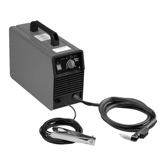
This warranty supersedes all previous warranties. PRODUCT DESCRIPTION The Firepower PC250 Plasma Cutting System includes the following: • 115V Power Supply/ 60 Hz • Power Supply provides 20 amps output cutting current. All electrical, pilot, and gas control circuitry is included. -
Page 10: Specifications And Features
SPECIFICATIONS FOR PC250 PLASMA CUTTING SYSTEM (1445-0927) Power Supply Type 10 - 20 AMP Plasma Cutting System Input Voltage 115V (60Hz) Rated Output 20A / 40% Duty Cycle Input Amperage Agency Approval Maximum Output Cut Capacity Most Materials up to ⁄... -
Page 11: Installation And Operation
INSTALLATION AND OPERATION SITE LOCATION CAUTION Select a clean, dry location with good ventilation and adequate working space around all components. Operation without proper air flow will inhibit proper cooling and reduce duty cycle. To prevent entry of cutting or other metal debris, the power supply must not be operated in the horizontal position. Operate the power supply in the vertical position only with the power supply control panel side up. -
Page 12: Functional Overview
The air pressure regulator assembly integrated in the machine is also an adequate filter and moisture trap. FUNCTIONAL OVERVIEW The Firepower PC250 Plasma Cutting System is designed to provide a plasma cutting system which can cut most metals from gauge thickness up to 1/4 inch (6.4 mm). OPERATING CONTROLS 1. -
Page 13: Getting Started
3. Red LED Is illuminated when there is output voltage. 4. Cutting current potentiometer 5. Yellow LED Indicates there is not enough air pressure. Pressure must be adjusted from 4 to 6 bar maximum (57-86 psi). If 6 bar is exceeded the internal solenoid valve releases air. 6. -
Page 14: Torch Consumables Parts Selection
TORCH CONSUMABLE PARTS SELECTION Part # Description 1445-0928 70deg Torch, 4m (13ft) Leads 1445-0929 Lead Assembly, 4m (13ft) Leads 1445-0930 70deg Torch Head 1445-0931 O-Ring 1445-0932 O-Ring 1445-0933 O-Ring 1445-0934 Electrode, Air/N2 1445-0935 Start Cartridge 1445-0936 Gas Distributor 1445-0937 Tip, Cutting, Air/N2 1445-0938 Coil Spring 1445-0939... -
Page 15: Operating Tips
OPERATING TIPS A. Piloting Piloting is harder on parts life than actual cutting because the pilot arc is directed from the electrode to the tip rather than to a workpiece. Whenever possible, avoid excessive pilot arc time to improve parts life. B. -
Page 16: Hand Torch Operation
HAND TORCH OPERATION A. Cutting with a Hand Torch 1. The torch can be comfortably held in one hand or steadied with two hands. Choose the technique that feels most comfortable and allows good control and movement. Position the index finger or thumb to press the con- trol switch on the torch handle. -
Page 17: General Maintenance
GENERAL MAINTENANCE A. Cleaning Power Supply The only routine maintenance required for the power supply is a thorough cleaning and inspection, with the frequency depending on the usage and the operating environment. Disconnect primary power to the system before disassembling the torch, leads, or power supply. WARNING CAUTION Do not blow air into the power supply during cleaning. -
Page 18: Inspection And Replacement Consumable Parts
3. Excessive Dross Formation a. Cutting speed too slow (bottom dross) b. Cutting speed too fast (top dross) c. Torch standoff too high from workpiece d. Worn torch parts e. Improper cutting current f. Non-Genuine Manufacturer's Parts 4. Short Torch Parts Life a. -
Page 19: Basic Troubleshooting Guide
BASIC TROUBLESHOOTING GUIDE A. General Basic troubleshooting of the Firepower PC250 plasma cutting system can be performed without special equipment or knowledge, and without opening the enclosure. This basic troubleshooting guide covers input power, gas supply, and torch problems. - Page 20 Make sure work lead is connected securely to bare metal. 2. AC input power too low a. Use shortest service to breaker panel possible. Refer to specifications for PC250 for input power cable requirements. 3. Faulty Main PC Board...
-
Page 21: Parts List
PARTS LISTS A. PC250 Power Supply Spare Parts Power Supply Item No. Part Number Description 1444-0482 ON/OFF SWITCH 16A 250V 1445-0952 POTENTIOMETER KNOB D.32 BLACK 1445-0953 FRONT VENT 1445-0954 FRONT FRAME 1445-0955 FRONT PANEL PC.BOARD PC 115V 1444-0434 HANDLE 1445-0957... -
Page 22: Spare Parts
B. PC250 Torch Spare Parts Part # Description 1445-0928 70deg Torch, 4m (13ft) Leads 1445-0929 Lead Assembly, 4m (13ft) Leads 1445-0930 70deg Torch Head 1445-0931 O-Ring 1445-0932 O-Ring 1445-0933 O-Ring 1445-0934 Electrode, Air/N2 1445-0935 Start Cartridge 1445-0936 Gas Distributor 1445-0937...
Need help?
Do you have a question about the PC250 and is the answer not in the manual?
Questions and answers