
Related Manuals for Firepower MST 220i


Summary of Contents for Firepower MST 220i
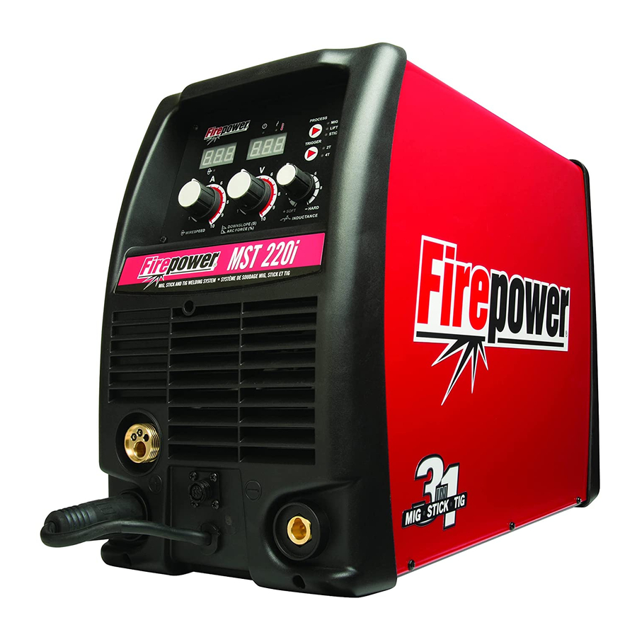
- Page 1 Firepower MST 220i 3-IN-1 Multi Process Welding Systems Operating Manual English Canadien Français Americas Español Revision: AA Issue Date: May 13, 2014 Manual No.: 0-5343 www.Firepower.com...
- Page 2 WE APPRECIATE YOUR BUSINESS! Congratulations on receiving your new Firepower product. We are proud to have you as our customer and will strive to provide you with the best service and support in the industry. This product is backed by our extensive warranty and world-wide service network.
- Page 3 While the information contained in this Manual represents the Manufacturer’s best judgment, the Manufacturer assumes no liability for its use. Operating Manual Number 0-5343 for: Firepower MST 220i Portable system Package Part Number: 1444-0872 Published by: Victor Technologies, Inc.
-
Page 4: Table Of Contents
2.04 Description ..................... 2-1 2.05 Transportation Methods .................. 2-2 2.06 User Responsibility ..................2-2 2.07 Firepower MST 220i Portable System Package (Part No. 1444-0872) .... 2-2 2.08 Duty Cycle ....................... 2-3 2.09 Specifications ....................2-4 2.10 Optional Accessories ..................2-5 2.11... - Page 5 Firepower Fusion 220A MIG Gun ..............6-1 6.02 Power Source Spare Parts ................6-2 APPENDIX 1: FIREPOWER MST 220i CIRCUIT DIAGRAM ..........A-1 FIREPOWER - LIMITED WARRANTY TERMS ........INSIDE REAR COVER GLOBAL CUSTOMER SERVICE CONTACT INFORMATION ......... REAR COVER...
- Page 6 This Page Intentionally Blank...
-
Page 7: Section 1: Safety Instructions And Warnings
FIREPOWER MST 220i SECTION 1: SAFETY INSTRUCTIONS AND WARNINGS WARNING PROTECT YOURSELF AND OTHERS FROM POSSIBLE SERIOUS INJURY OR DEATH. KEEP CHILDREN AWAY. PACEMAKER WEARERS KEEP AWAY UNTIL CONSULTING YOUR DOCTOR. DO NOT LOSE THESE INSTRUCTIONS. READ OPERATING/INSTRUCTION MANUAL BEFORE INSTALLING, OPERATING OR SERVICING THIS EQUIPMENT. - Page 8 FIREPOWER MST 220i 3. Use protective screens or barriers to protect others from flash and glare; warn others not to watch the arc. WARNING 4. Wear protective clothing made from durable, ARC RAYS can burn eyes and skin; NOISE flame-resistant material (wool and leather) and can damage hearing.
- Page 9 FIREPOWER MST 220i 1. Keep your head out of the fumes. Do not breathe 7. Do not weld on closed containers such as tanks the fumes. or drums. 2. If inside, ventilate the area and/or use exhaust at 8. Connect work cable to the work as close to the the arc to remove welding fumes and gases.
- Page 10 FIREPOWER MST 220i 4. To prevent accidental starting during servicing, 8. Read and follow instructions on compressed disconnect negative (-) battery cable from gas cylinders, associated equipment, and CGA battery. publication P-1 listed in Safety Standards. 5. Keep hands, hair, loose clothing, and tools away from moving parts.
-
Page 11: General Safety Information For Victor Cs Regulator
FIREPOWER MST 220i 1.02 General Safety Information For NOTE Victor CS Regulator Considerations About Welding And The Effects of Low Frequency Electric and Fire Prevention Magnetic Fields Welding and cutting operations use fire or combus- The following is a quotation from the General Con- tion as a basic tool. - Page 12 FIREPOWER MST 220i Ventilation Compressed Gas Cylinders The Department of Transportation (DOT) approves the design and manufacture of cylinders that contain WARNING gases used for welding or cutting operations. Ade quately ventilate welding, heating, and 1. Place the cylinder (Figure 1-1) where you will cutting work areas to prevent accumula- use it.
-
Page 13: Principal Safety Standards
FIREPOWER MST 220i 6. Momentarily open and close (called “cracking”) 1.03 Principal Safety Standards the cylinder valve to dislodge any dust or dirt that may be present in the valve. Safety in Welding and Cutting, ANSI Standard Z49.1, from American Welding Society, 550 N.W. LeJeune Rd., Miami, FL 33126. -
Page 14: Symbol Chart
FIREPOWER MST 220i 1.04 Symbol Chart Note that only some of these symbols will appear on your model. Wire Feed Function Single Phase Wire Feed Towards Workpiece With Three Phase Output Voltage Off. Three Phase Static Frequency Converter- Welding Gun... -
Page 15: Precautions De Securite En Soudage A L'arc
FIREPOWER MST 220i 1.05 Precautions De Securite En Soudage A L’arc MISE EN GARDE LE SOUDAGE A L’ARC EST DANGEREUX PROTEGEZ-VOUS, AINSI QUE LES AUTRES, CONTRE LES BLESSURES GRAVES POSSIBLES OU LA MORT. NE LAISSEZ PAS LES ENFANTS S’APPROCHER, NI LES PORTEURS DE STIMULATEUR CARDIAQUE (A MOINS QU’ILS N’AIENT CONSULTE UN MEDECIN). - Page 16 FIREPOWER MST 220i 12. N’utilisez que des équipements en bon état. Répa- rez ou remplacez aussitôt les pièces endomma- gées. AVERTISSEMENT 13. Dans des espaces confinés ou mouillés, n’utilisez LE RAYONNEMENT DE L’ARC PEUT BRÛ- pas de source de courant alternatif, à moins qu’il LER LES YEUX ET LA PEAU;...
- Page 17 FIREPOWER MST 220i 2. Portez des lunettes de sécurité approuvées. Des écrans latéraux sont recommandés. 3. Entourez l’aire de soudage de rideaux ou de cloi- AVERTISSEMENT sons pour protéger les autres des coups d’arc ou LE SOUDAGE PEUT CAUSER UN INCEN- de l’éblouissement;...
- Page 18 FIREPOWER MST 220i pantalon revers, des bottines de sécurité et un 8. Lisez et respectez les consignes relatives aux bouteilles de gaz comprimé et aux équipements casque. connexes, ainsi que la publication P-1 de la CGA, identifiée dans la liste de documents ci-dessous.
- Page 19 FIREPOWER MST 220i 1. Assurez-vous que les portes, les panneaux, les 3. Laissez la pression s’échapper avant d’ôter com- capots et les protecteurs soient bien fermés. plètement le bouchon. 2. Avant d’installer ou de connecter un système, arrêtez le moteur.
-
Page 20: Informations Générales De Sécurité
FIREPOWER MST 220i Entretien des Locaux STIMULATEURS CARDIAQUES : AVERTISSEMENT Les procédures décrites ci-dessus sont Ne laissez jamais l’oxygène en contact habituellement celles recommandées pour avec la graisse, l’huile ou d’autres subs- les porteurs de stimulateurs cardiaques. tances inflammables. Bien que l’oxygène Pour de plus amples renseignements, elle même ne brûle pas, ces substances... - Page 21 FIREPOWER MST 220i Bouteilles de Gaz Comprimé AVERTISSEMENT Le Département des Transports américain (DOT) approuve la conception et la fabrication des bouteilles N’UTILISEZ PAS la bouteille si vous trou- qui contiennent les gaz utilisés pour les opérations de vez de l’huile, de la graisse ou des pièces soudage ou de découpage.
-
Page 22: Principales Normes De Securite
FIREPOWER MST 220i 1.08 Principales Normes De Securite Safety in Welding and Cutting, norme ANSI Z49.1, American Welding Society, 550 N.W. LeJeune Rd., Miami, FL 33128. Safety and Health Standards, OSHA 29 CFR 1910, Superintendent of Documents, U.S. Government Printing Office, Washington, D.C. 20402. -
Page 23: Graphique De Symbole
FIREPOWER MST 220i 1.09 Graphique de Symbole Seulement certains de ces symboles apparaîtront sur votre modèle. Déroulement du Fil Sous Tension Mono Phasé Alimentation du Fil Vers la Pièce de Fabrication Hors Tension Trois Phasé Hors Tension Tri-Phase Statique Torche de Soudage Tension dangereuse Fréquence Convertisseur... - Page 24 FIREPOWER MST 220i This Page Intentionally Blank SAFETY INSTRUCTIONS AND WARNINGS 1-18 Manual 0-5343...
-
Page 25: Section 2: Introduction
Gives information regarding possible electri- 2.04 Description cal shock injury. Warnings will be enclosed The Firepower MST 220i is a self contained single in a box such as this. phase multi process welding system that is capable of performing MIG (GMAW/FCAW), STICK (SMAW) and LIFT TIG (GTAW) welding processes. -
Page 26: Transportation Methods
Accredited Firepower Distributor. This equipment or any of its parts should not be altered from standard specification without prior written ap- proval of Firepower. The user of this equipment shall Art # A-12523 have the sole responsibility for any malfunction which... -
Page 27: Duty Cycle
Figure 2-2: Firepower MST 220i Duty Cycle on 208/230VAC FIREPOWER MST 220i STICK SAFE OPERATING REGION (MIG, TIG & STICK) 100 110 120 130 140 150 Welding Current (AMPS) Art # A-12525 Figure 2-3: Firepower MST 220i Duty Cycle on 115V AC Manual 0-5343 INTRODUCTION... -
Page 28: Specifications
FIREPOWER MST 220i 2.09 Specifications Description Firepower MST 220i Multi Process 3 in 1 Welder Power Source Part No. 1444-0872 Power Source Dimensions H17.12” x W10.47” x D 24.29” (435mm x 266mm x D617mm) Power Source Mass 57.3lb (26.5kg) Cooling... -
Page 29: Optional Accessories
Power Source (Based on Article 630, National Electrical Code) Firepower continuously strives to produce the best product possible and therefore reserves the right to change, improve or revise the specifications or design of this or any product without prior notice. -
Page 30: Volt-Ampere Curves
FIREPOWER MST 220i 2.11 Volt-Ampere Curves Voltage-Amperage Curves shows maximum voltage and amperage output capabilities of welding power source. Curves of other settings fall between curves shown. Art # A-11297 Figure 2-4: Firepower MST 220i Volt-Ampere Curves INTRODUCTION Manual 0-5343... -
Page 31: Section 3: Installation, Operation And Setup
FIREPOWER MST 220i SECTION 3: INSTALLATION, OPERATION AND SETUP F. Place at a distance of 12" (305mm) or more from 3.01 Environment walls or similar that could restrict natural air flow This Power Source is designed for use in environments for cooling. - Page 32 FIREPOWER MST 220i WARNING The Firepower MST 220i must be electrically connected by a qualified electrical trades-person. Dam- age to the PCA (Power Control Assembly) could occur if 265 VAC or higher is applied to the Primary Power Cable. WARNING ELECTRIC SHOCK can kill;...
- Page 33 FIREPOWER MST 220i WARNING An electrical shock or fire hazard is probable if the following electrical service guide recommendations are not followed. These recommendations are for a dedicated branch circuit sized for the rated output and duty cycle of the welding Power Source.
-
Page 34: Electromagnetic Compatibility
FIREPOWER MST 220i 3.05 Electromagnetic Compatibility WARNING Extra precautions for Electromagnetic Compatibility may be required when this Welding Power Source is used in a domestic situation. A. Installation and Use - Users Responsibility The user is responsible for installing and using the welding equipment according to the manufacturer’s instructions. -
Page 35: Firepower Regulator
FIREPOWER MST 220i 2. Maintenance of Welding Equipment The welding equipment should be routinely maintained according to the manufacturer’s recommendations. All access and service doors and covers should be closed and properly fastened when the welding equipment is in operation. The welding equipment should not be modified in any way except for those changes and adjustments covered in the manufacturer’s instructions. - Page 36 FIREPOWER MST 220i NOTE Regulators purchased with open 1/8”, 1/4”, 3/8”, or 1/2” NPT ports must be assembled to their intended system. 1. Note the maximum inlet pressure stamped on the regulator. DO NOT attach the regulator to a system that has a higher pressure than the maximum rated pressure stamped on the regulator.
- Page 37 FIREPOWER MST 220i 7. Before opening the cylinder valve, turn the regulator adjusting screw counterclockwise until there is no pressure on the adjusting spring and the screw turns freely. 8. Relief Valve (where provided): The relief valve is designed to protect the low pressure side of the regulator from high pres sures.
-
Page 38: Leak Testing The System
FIREPOWER MST 220i 3.07 Leak Testing The System Leak test the system before putting into operation. 1. Be sure that there is a valve in the downstream equipment to turn OFF the gas flow. 2. With the cylinder valve open, adjust the regulator to deliver the maximum required delivery pressure. -
Page 39: Firepower Mst 220I Power Source Controls, Indicators And Features
FIREPOWER MST 220i 3.10 Firepower MST 220i Power Source Controls, Indicators And Features SOFT HARD E (S) Art # A-12526 Figure 3-6: Front and Control Panel Figure 3-7: Rear Panel Connections Art # A-10938 Figure 3-8: Wire Feed Compartment Control... - Page 40 FIREPOWER MST 220i 1. Power Indicator The power indicator is illuminated when the correct mains power is applied to the power source and when the ON/OFF switch located on the rear panel is in the ON position. 2. Thermal Overload Indicator (Fault Indicator) This welding power source is protected by a self resetting thermostat.
- Page 41 FIREPOWER MST 220i 4. Wirespeed/Amperage Control In MIG mode, the Wirespeed/Amperage control knob adjusts the speed of the wire feed motor (which in turn adjusts the output current by varying the amount of MIG wire delivered to the welding arc). The optimum wire speed depends upon the material type and the welding application.
- Page 42 FIREPOWER MST 220i 8. Negative Welding Output Terminal The negative welding terminal is used to connect the welding output of the power source to the appropriate welding accessory such as the MIG gun (via the MIG polarity lead), TIG torch or work lead. Negative welding current flows to the power source via this dinse type terminal.
- Page 43 FIREPOWER MST 220i When MIG Mode is Selected In this mode the control knob is used to adjust the output voltage of the unit. The welding voltage is increased by turning the knob clockwise or decreased by turning the knob anti-clockwise. The optimum voltage level required will dependent on the type of welding application.
- Page 44 FIREPOWER MST 220i 13. Process Selection Control The process selection control is used to select the desired welding mode. Three modes are available, MIG (GMAW/FCAW), LIFT TIG (GTAW) and STICK (SMAW) modes. Refer to section 3.19 or 3.20 for MIG (GMAW/ FCAW) set up details, section 3.22 for LIFT TIG (GTAW) set-up details or section 3.23 for STICK (SMAW)
- Page 45 21. Cooling Fan The Firepower MST 220i is designed with an intelligent fan control. When the 220i is switched ON the cooling fan will come ON for approximately 3 seconds then automatically switch the fan OFF. The cooling fan will remain OFF until it is required for cooling purposes.
-
Page 46: Attaching The Firepower Fusion 220A Mig Gun
FIREPOWER MST 220i 3.11 Attaching the Firepower Fusion 220A MIG Gun Fit the MIG Torch to the power source by pushing the MIG torch connector into the MIG torch adaptor and screw- ing the plastic torch nut clockwise to secure the MIG torch to the MIG torch adaptor. -
Page 47: Installing 33/44 Lb Spool (12" Diameter)
FIREPOWER MST 220i 3.12 Installing 33/44 lb Spool (12" diameter) As delivered from the factory, the unit is fitted with a Wire Spool Hub which accepts a Spool of 33/44 lb. or 12" diameter. Installation of wire spool, Refer to Figure 3-11. -
Page 48: Installing 12.5 Lb Spool ( 8" Diameter)
FIREPOWER MST 220i 3.13 Installing 12.5 lb Spool ( 8" diameter) In order to fit a 12.5 lb spool (8" diameter) assemble parts in the sequence shown in Figure 3-9. Installation of wire spool: 1. Remove Wire Spool Hub Retaining Clip. Grasp the loop and pull. -
Page 49: Installing 1 Lb Spool (4" Diameter)
FIREPOWER MST 220i 3.14 Installing 1 lb Spool (4" diameter) In order to fit a 1 lb spool (4" diameter) assemble parts in the sequence shown in Figure 3-13. Installation of wire spool: 1. Remove Wire Spool Hub Retaining Clip. Grasp the loop and pull. -
Page 50: Inserting Wire Into The Wire Feed Mechanism
FIREPOWER MST 220i 3.15 Inserting Wire Into The Wire Feed Mechanism Release the tension from the pressure roller by turning the adjustable wire drive tension knob in an anti-clockwise direction. Then to release the pressure roller arm push the tension screw toward the back of the machine which releases the pressure roller arm (Figure 3-14). -
Page 51: Feed Roller Pressure Adjustment
FIREPOWER MST 220i 3.16 Feed Roller Pressure Adjustment The pressure (top) roller applies pressure to the grooved feed roller via an adjustable pressure screw. These devices should be adjusted to a minimum pressure that will provide satisfactory WIREFEED without slippage. If slipping occurs, and inspection of the wire contact tip reveals no wear, distortion or burn back jam, the conduit liner should be checked for kinks and clogging by metal flakes and swarf. -
Page 52: Wire Reel Brake
C. Fit the MIG gun to the power source. (Refer to section 3.11 Attaching the Firepower Fusion 220A MIG Gun). D. Connect the work lead to the negative welding terminal (-). If in doubt, consult the electrode wire manufacturer. - Page 53 FIREPOWER MST 220i WARNING Before connecting the work clamp to the work make sure the Electricity Supply is switched OFF. Secure the welding grade shielding gas cylinder in an upright position by chaining it to a suitable sta- tionary support to prevent falling or tipping.
-
Page 54: Setup For Mig (Fcaw) Welding With Flux Core (Gasless) Wire
FIREPOWER MST 220i 3.20 Setup For MIG (FCAW) Welding With Flux Core (Gasless) Wire A. Select MIG mode with the process selection control (refer to Section 3.10 for further information). B. Connect the MIG polarity lead to the negative welding terminal (-). If in doubt, consult the electrode wire manufacturer. -
Page 55: Setup For Spool Gun Mig (Gmaw) Welding With Gas Shielded Mig Wire
A-12537 OFF before connecting the welding gun. NOTE If the Firepower MST 220 has already been setup for MIG Welding you will have to re- move the MIG Gun and retract the welding wire out of the wirefeeder before beginning the next step. -
Page 56: Setup For Lift Tig (Gtaw) Welding
FIREPOWER MST 220i 3.22 Setup For LIFT TIG (GTAW) Welding A. Select LIFT TIG mode with the process selection control (refer to Section 3.10 for further information). B. Connect the TIG Torch to the negative welding terminal (-). Welding current flows from the power source via dinse type terminals. - Page 57 FIREPOWER MST 220i Art # A-12538 Connect to shielding gas regulator/flow gauge. Secure the gas cylinder in an upright position by Positive Welding chaining it to a stationary Terminal (+) support to prevent falling or tipping. Work Lead Negative Welding...
-
Page 58: Setup For Stick (Smaw) Welding
FIREPOWER MST 220i 3.23 Setup For STICK (SMAW) Welding A. Connect the Electrode Holder lead to the positive welding terminal (+). If in doubt, consult the electrode manu- facturer. Welding current flows from the Power Source via dinse type terminals. It is essential, however, that the male plug is inserted and turned securely to achieve a sound electrical connection. -
Page 59: Basic Welding Guide
FIREPOWER MST 220i SECTION 4: Shielding Gas Nozzle (Optional) (Optional) BASIC WELDING GUIDE Molten Metal Flux Cored Molten Electrode 4.01 MIG (GMAW/FCAW) Basic Welding Slag Slag Technique Solidified Base Metal Two different welding processes are covered in this sec- Weld Metal... - Page 60 FIREPOWER MST 220i Preselected Variables Preselected variables depend upon the type of material 5° to 15° Longitudinal Angle being welded, the thickness of the material, the welding 30° to 60° position, the deposition rate and the mechanical proper- Transverse Angle ties.
- Page 61 FIREPOWER MST 220i Setting of the Power Source Transverse Angle Power source setting requires some practice by the operator, as the welding plant has two control settings that have to balance. These are the Wirespeed control (refer to section 3.06.4) and the welding Voltage Con- Longitudinal trol (refer to section 3.06.10).
- Page 62 FIREPOWER MST 220i Firepower MIG, Lift TIG, Stick Wire Selection Chart Table 4-1 NOTE Please refer to the inside panel of the machine for the same chart. BASIC WELDING Manual 0-5343...
-
Page 63: Mig (Gmaw/Fcaw) Welding Troubleshooting
FIREPOWER MST 220i 4.02 MIG (GMAW/FCAW) Welding Troubleshooting Solving Problems Beyond the Welding Terminals The general approach to fix MIG (GMAW/FCAW) welding problems is to start at the wire spool then work through to the MIG Gun. There are two main areas where problems occur with GMAW; Porosity and Inconsistent wire feed. - Page 64 FIREPOWER MST 220i Solving Probelms Beyond the Welding Terminals - Inconsistent Wire Feed WARNING Disengage the feed roll when testing for gas flow by ear. Wire feeding problems can be reduced by checking the following points. FAULT CAUSE 1 Feed roller driven by motor in the Wire spool brake is too tight.
- Page 65 9 Poor weld result from Contact tip has arc marks in Replace the contact tip with only a Genuine Firepower setup chart parameters the bore causing excessive Velocity contact tip. drag on the wire.
-
Page 66: Stick (Smaw) Basic Welding Technique
Electrodes are generally connected to the ELECTRODE HOLDER with the Electrode Holder connected positive polarity. The WORK LEAD is connected negative polarity and is connected to the work piece. If in doubt consult the electrode data sheet or your nearest Accredited Firepower Distributor. 4.04 Effects of Arc Welding Various Materials A. - Page 67 FIREPOWER MST 220i Art # A-07687 Art# A-07693 Figure 4-11: Flat Position, Down Hand Butt Weld Figure 4-17: Overhead Position, Butt Weld Art # A-07688 Art # A-07694 Figure 4-12: Flat Position, Gravity Fillet Weld Figure 4-18: Overhead Position, Fillet Weld...
- Page 68 FIREPOWER MST 220i Open Square Butt Single Vee Butt Joint Not less than 70° Joint 1/16” (1.6mm) max Gap varies from 1/16” (1.6mm) to 3/16” (4.8mm) depending on plate thickness 1/16” (1.6mm) Not less than Single Vee Butt Joint Double Vee Butt Joint Not less than 45°...
- Page 69 FIREPOWER MST 220i If the lead is slung over your shoulder, it allows greater Rate of Travel freedom of movement and takes a lot of weight off After the arc is struck, your next concern is to maintain your hand. Be sure the insulation on your cable and...
- Page 70 FIREPOWER MST 220i 45° from vertical 60° - 70° from line of weld Art # A-07698 Figure 4-22: Weld Build up Sequence Art # A-07699_AB Heavy plate will require several runs to complete Figure 4-23: Electrode Position for HV Fillet Weld the joint.
- Page 71 FIREPOWER MST 220i 3. Overhead Welds Art # A-07701 Apart from the rather awkward position neces- sary, overhead welding is not much more dif- ficult that downhand welding. Set up a specimen for overhead welding by first tacking a length of angle iron at right angles to another piece of angle iron or a length of waste pipe.
- Page 72 FIREPOWER MST 220i The Cause of Distortion Upsetting Weld Art # A-07705_AB Distortion is caused by: Expansion with compression A. Contraction of Weld Metal: Cool Molten steel shrinks approximately 11 per cent Figure 4-29: Parent Metal Expansion in volume on cooling to room temperature. This...
- Page 73 FIREPOWER MST 220i E. Preheating Suitable preheating of parts of the structure other than the area to be welded can be sometimes used to reduce distortion. Figure 4-32 shows a simple application. By removing the heating source from b and c as soon as welding is completed, the sec-...
-
Page 74: Stick (Smaw) Welding Troubleshooting
FIREPOWER MST 220i 4.05 STICK (SMAW) Welding Troubleshooting FAULT CAUSE REMEDY 1 Welding current ARC FORCE is set at a val- Reduce the ARC FORCE until welding current is varying ue that causes the welding reasonably constant while prohibiting the elec-... - Page 75 FIREPOWER MST 220i FAULT CAUSE REMEDY 4 A groove has been A Welding current is too A Reduce welding current. formed in the base high. metal adjacent to B Welding arc is too long. B Reduce the length of the welding arc.
-
Page 76: Tig (Gtaw) Basic Welding Technique
FIREPOWER MST 220i 4.06 TIG (GTAW) Basic Welding Technique Gas Tungsten Arc Welding (GTAW) or TIG (Tungsten Inert Gas) as it is commonly referred to, is a welding process in which fusion is produced by an electric arc that is established between a single tungsten (non-consumable) electrode and the work piece. - Page 77 Grey num, magnesium and range, Narrower more their alloys concentrated arc. Table 4-8 NOTE The Firepower MST 220i Inverter is not suited for AC TIG welding. TIG Welding Filler Rods Base Metal DC Current DC Current Tungsten Filler Rod Argon Gas...
-
Page 78: Tig (Gtaw) Welding Problems
FIREPOWER MST 220i 4.07 TIG (GTAW) Welding Problems FAULT CAUSE REMEDY 1 Excessive bead build up or Welding current is too Increase weld current and/or faulty joint poor penetration or poor preparation. fusion at edges of weld. 2 Weld bead too wide and Welding current is too Decrease weld current. - Page 79 FIREPOWER MST 220i FAULT CAUSE REMEDY 7 Dirty weld pool A Electrode contaminated A Clean the electrode by grinding off the by contact with work contaminates. piece or filler rod mate- rial. B Work piece surface has B Clean surface.
- Page 80 FIREPOWER MST 220i This Page Intentionally Blank BASIC WELDING 4-22 Manual 0-5343...
-
Page 81: Section 5: Power Source Problems And Routine Service Requirements
(burn-back jam). tact tip. Replace faulty compo- nents. B Internal fault in power B Have an Accredited Firepower source Service Provider investigate the fault. 4 Welding wire continues to A Trigger mode selection... -
Page 82: Routine Service And Calibration Requirements
There are extremely dangerous voltage and power levels present inside this Inverter Power Source. Do not attempt to open or repair unless you are an accredited Firepower Service Provider. Disconnect the Welding Power Source from the Electricity Supply before disassembling. - Page 83 2. The earth terminal of the associated plug of a transportable power source Note that due to the dangers of stray output currents damaging fixed wiring, the integrity of fixed wiring sup- plying Firepower welding power sources should be inspected by a licensed electrical worker in accordance with the requirements below - 1.
- Page 84 Output current (A) to be checked to ensure it falls within applicable Firepower power source specifications Output Voltage (V) to be checked to ensure it falls within applicable Firepower power source specifications Motor Speed (RPM) of wire drive motors to be checked to ensure it falls within required Firepower power source / wire feeder specifications...
-
Page 85: Cleaning The Welding Power Source
FIREPOWER MST 220i 5.03 Cleaning the Welding Power Source WARNING There are dangerous voltage and power levels present inside this product. Do not attempt to open or repair unless you are a qualified electrical tradesperson. Disconnect the Welding Power Source from the Electricity Supply before disassembling. -
Page 86: Cleaning The Feed Rolls
FIREPOWER MST 220i 5.04 Cleaning the Feed Rolls Clean the grooves in the drive rolls frequently. This can be done by using a small wire brush. Also wipe off, or clean the grooves on the upper feed roll. After cleaning, tighten the feed roll retaining knobs. -
Page 87: Section 6: Key Spare Parts
Handle / Trigger Repair Kit 1444-0883 Universal Conduit Liner* Conductor Tube, Firepower Fusion 16201108 140A/180A/220A MIG Gun, 60 Deg Table 6-1: Firepower Fusion 220A MIG Gun Parts ** Patent Pending * Refer to your Firepower Catalog for additional options. Figure 6-1 Manual 0-5343... -
Page 88: Power Source Spare Parts
FIREPOWER MST 220i 6.02 Power Source Spare Parts Figure 6-2 REPLACEMENT PARTS Manual 0-5343... - Page 89 Label, Identification, FP MST220i (not shown) 1444-0928 Setup chart, English version, FP MST220i (not shown) 1444-0912 Large Spring, for One Pound Spool (not shown) W7005635 Latch, Door, Slide (not shown) Table 6-2: Firepower MST 220i Parts Manual 0-5343 REPLACEMENT PARTS...
- Page 90 FIREPOWER MST 220i This Page Intentionally Blank REPLACEMENT PARTS Manual 0-5343...
-
Page 91: Appendix 1: Firepower Mst 220I Circuit Diagram
FIREPOWER MST 220i APPENDIX 1: FIREPOWER MST 220i CIRCUIT DIAGRAM 1 +24VDC BLACK BLACK +24CDC 1 N/A 2 WHITE WHITE WHITE WHITE +24VDC WHITE WHITE 1 +5VDC INPUT 230V/115V YELLOW OUTPUT CONTROL SIGNAL 2 TO U15 PIN6 1 PWM RETURN... - Page 92 FIREPOWER MST 220i This page intentionally blank APPENDIX Manual 0-5343...
-
Page 93: Firepower - Limited Warranty Terms
“Purchaser” that its products will be free of defects in workmanship or material. Should any failure to conform to this warranty appear within the time period applicable to the FIREPOWER products as stated below, FIREPOWER shall, upon notification thereof and substantiation that the product has been stored, installed, operated, and maintained in accordance with FIREPOWER’s specifications, instructions, recommendations and... - Page 94 This page intentionally blank...
-
Page 95: Warranty Schedule
* 2 years on Power Supply Components 2 Years Parts / No Labor Auto-Darkening Welding Helmet (electronic Lens), ** 1 Month Harness Assy Firepower Regulator for Firepower MST 220i (No labor) 90 days parts / No Labor Remote Controls MIG and TIG Torches (Supplied with power sources) - Page 96 THE AMERICAS Denton, TX USA U.S. Customer Care Ph 1-800-426-1888 (tollfree) Fax: 1-800-535-0557 (tollfree) International Customer Care Ph 1-940-381-1212 Fax: 1-940-483-8178 Miami, FL USA Sales Office, Latin America Ph 1-954-727-8371 Fax: 1-954-727-8376 Oakville, Ontario, Canada Canada Customer Care Ph 1-905-827-4515 Fax: 1-800-588-1714 (tollfree) EUROPE Chorley, United Kingdom...
Need help?
Do you have a question about the MST 220i and is the answer not in the manual?
Questions and answers
BLINKING GREEN LIGHT IN FRONT POWER NOT COMING ON