
Related Manuals for Firepower FP-120


Summary of Contents for Firepower FP-120
- Page 1 FP-120, FP-130 and FP-160 MIG Welding System Instruction Manual FORM NO. 0056-1842 EFFECTIVE July 2001 Safety and Operating Instructions For Your Safety . . . PLEASE READ CAREFULLY!
-
Page 2: Table Of Contents
Troubleshooting Guide for Firepower FP-200 MIG Gun ........ - Page 3 Firepower Limited Warranty ........
-
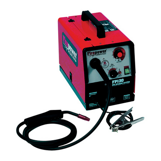
Page 4: Introduction
SAFETY INFORMATION The following safety information is provided to you as a guideline. Use it to operate your new Firepower Welding System under the safest possible conditions. Any equipment that uses electrical power is potentially dangerous to use when the safety or safe handling instructions are not known and/or are not followed. - Page 5 Indicates that the helmet must be worn during the step(s) that follow to protect against eye damage and burns due to flash hazard. Indicates that the possibility of toxic gas hazard exists during operation of the step(s) that follow. Indicates that the possibility of being burned by hot slag exists during operation of the step(s) that follow.
-
Page 6: General Welding Safety Instructions
IMPROPER HANDLING AND MAINTENANCE OF COMPRESSED GAS CYLINDERS AND REGULATORS CAN RESULT IN SERIOUS INJURY OR DEATH! Reduce the risk of injury or death from compressed gasses and equipment hazards. Read, understand and follow the following safety instructions. Additionally, make certain that anyone else who uses this welding equipment, or who is a bystander in the welding area, understands and follows these safety instructions as well. -
Page 7: Ventilation
5. Remove all combustible materials from the work site. If you can not remove them, protect them with fire- proof covers. NEVER perform welding operations on a container that has held toxic, com- bustible or flammable liquids or vapors. NEVER perform welding operations in an area con- taining combustible vapors, flammable liquids or explosive dust. -
Page 8: Health Hazards
WELDER SPECIFICATIONS Your new Firepower Wire MIG (GMAW) and Flux Core (FCAW) Wire Welding System is designed for main- tenance and sheet metal fabrication. The unit consists of a single-phase power transformer power source, arc stabilizer, rectifier and heavy-duty wire feed system. -
Page 9: Welder Operating Characteristics
Power Cord ..........6 foot 15 Amp NEMA 5-15 Power Plug MIG Gun ....10 foot FIREPOWER ® with ON/OFF Contactor Control-Gas Valve in Handle Ground Cable and Clamp . -
Page 10: Specifications For Fp 130 Wire (Gmaw/Fcaw) Welding System (1444-0306)
Power Cord ..........6 foot 15 Amp NEMA 5-15 Power Plug MIG Gun ....10 foot FIREPOWER ® with ON/OFF Contactor Control-Gas Valve in Handle Ground Cable and Clamp . -
Page 11: Duty Cycle
DO NOT OPERATE THE FP-120 OR FP-130 WELDER if the ACTUAL power source voltage is less than 110 Volts AC or greater than 132 Volts AC. Contact a qualified electrician if this problem exists. Improper per- formance and/or damage to the welder will result if operated on inadequate or excessive power. -
Page 12: Mig Gun Installation
MIG GUN INSTALLATION This unit uses a Firepower MIG Gun furnished with rear connections that fit directly into the wire drive assem- bly. These guns are referred to as “Direct Connect” MIG Guns and are easy to install. Firepower “Direct Connect”... -
Page 13: Installation Of The Welding Wire
INSTALLATION OF THE WELDING WIRE The power source is supplied with a spool of .030 MIG Welding Wire. Install the wire into the feeding system by following the instructions below and referring to Figure 3. MIG (GMAW) welding applications require argon shielding gas. -
Page 14: Gas Cylinder And Regulator Connection
When changing the wire diameter being used, or replacing the wire feed roll, be sure that the correct groove for the wire diameter selected is inside, closest to the machine. The wire is driven by the inside groove. Feed rolls are marked on the side identifying the nearest groove. -
Page 15: Gasless Welding
DO NOT use the cylinder if you find oil, grease or damaged parts. Inform your gas supplier of this condition immediately. 1. Connect the FP-160 welding machine to a 230V, 60 Hz line. Connect the FP-120 or FP-130 to a 120V, 20 AMP, 60 Hz line. -
Page 16: Welding Procedures
IMPORTANT Make sure that the polarity of torch and ground cable is correctly set. For gasless welding, the ground cable must be connected to the positive ter- minal (+), while the torch must be connected to the neg- ative terminal (-) (see Figure 4). 3. -
Page 17: Replacement Of The Wire Spool
Spot welding is possible by replacing the welding nozzle with a spot welding nozzle. You can buy the spot welding nozzle from any supplier of Firepower Welding Systems. Spot welding can be performed on carbon steel sheets of 18 gauge thickness. -
Page 18: Additional Safety Information
The torch switch must be pressed thoroughly to perform its three functions: gas flow, wire feed and welding current.) Start welding and decrease the wire speed gradually. Continue to decrease the wire speed and listen to the sound. The sound will change from a crackling noise to a regular and strong buzzing (similar to the sound of frying bacon). -
Page 19: Troubleshooting Information
TROUBLESHOOTING INFORMATION Use this chart to assist you in resolving common problems you may encounter. These are not all of the possible solutions. ROBLEM OSSIBLE AUSE EMEDY 1. Dirty, porous or brittle weld. Plugged welding nozzle. Clean or replace welding nozzle. 2. -
Page 20: General Operating Tips
Regularly inspect the conductor tube, handle, cable hose, and other parts of the MIG gun for abrasion, cuts, or undue wear. Replace or repair any parts found deficient. TROUBLESHOOTING GUIDE FOR FIREPOWER FP-200 MIG GUN ROBLEM OSSIBLE... -
Page 21: Fp-200 Wire Liner Replacement
FP-200 WIRE LINER REPLACEMENT To remove the wire liner: 1. Lay the MIG gun out on a table or on the floor in a straight line. Make sure the gun is fully extended and all twists in the cable are removed. 2. -
Page 28: Figure 11: Fp 120 Wiring Diagram
Figure 11: FP 120 Wiring Diagram... -
Page 29: Figure 12: Fp 130 Wiring Diagram
Figure 12: FP 130 Wiring Diagram... -
Page 30: Figure 13: Fp 160 Wiring Diagram
Figure 13: FP 160 Wiring Diagram... -
Page 31: Firepower Limited Warranty
Notwithstanding the foregoing, • Firepower oxygen / acetylene products will be covered by a two-year product replacement warranty • Firepower plasma cutting equipment will be covered by a one-year (parts & labor) warranty. • Firepower electric welding machines will be covered by the Firepower 5-2-1 limited warranty. - Page 32 LIMITED WARRANTY CLAIM METHOD: To make a claim under this warranty, Purchaser must notify Seller of the details of such claim within thirty days of discovering a defect in material or work- manship. If the claim is covered by this warranty, Seller will direct Purchaser to return the product to an authorized warranty repair center.
Need help?
Do you have a question about the FP-120 and is the answer not in the manual?
Questions and answers