
Subscribe to Our Youtube Channel
Related Manuals for Firepower FP-100


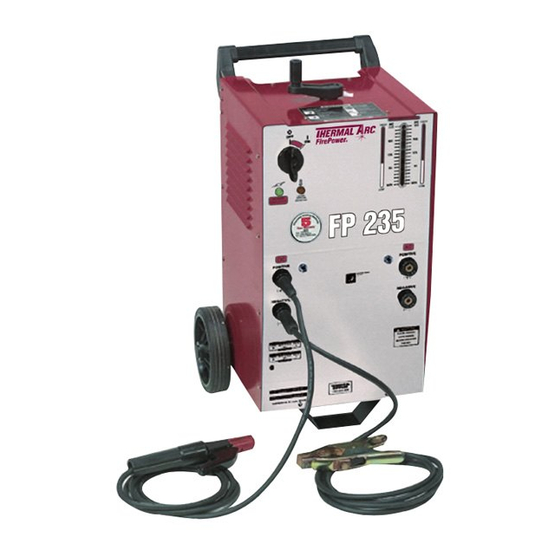
Summary of Contents for Firepower FP-100
- Page 1 FP-100, FP-235 and FP-235AC/DC Arc Welding System Instruction Manual FORM NO. 0056-1841 EFFECTIVE July 2001 Safety and Operating Instructions For Your Safety . . . PLEASE READ CAREFULLY!
-
Page 3: Table Of Contents
Internal Thermal Overload Protection (FP-100 ONLY) ......... .5 Specifications for FP-100 Arc(SMAW) Welding System (1443-0402) ......6 Specifications for FP-235 Arc(SMAW) Welding System (1443-0404) . - Page 4 Figure 12: FP-100 Parts Breakdown ........
-
Page 5: Introduction
SAFETY INFORMATION The following safety information is provided to you as a guideline. Use it to operate your new Firepower Welding System under the safest possible conditions. Any equipment that uses electrical power is potentially dangerous to use when the safety or safe handling instructions are not known and/or are not followed. - Page 6 Indicates that the helmet must be worn during the step(s) that follow to protect against eye damage and burns due to flash hazard. Indicates that the possibility of toxic gas hazard exists during operation of the step(s) that follow. Indicates that the possibility of being burned by hot slag exists during operation of the step(s) that follow.
-
Page 7: General Welding Safety Instructions
IMPROPER HANDLING AND MAINTENANCE OF COMPRESSED GAS CYLINDERS AND REGULATORS CAN RESULT IN SERIOUS INJURY OR DEATH! Reduce the risk of injury or death from compressed gasses and equipment hazards. Read, understand and follow the following safety instructions. Additionally, make certain that anyone else who uses this welding equipment, or who is a bystander in the welding area, understands and follows these safety instructions as well. -
Page 8: Ventilation
5. Remove all combustible materials from the work site. If you can not remove them, protect them with fire- proof covers. NEVER perform welding operations on a container that has held toxic, com- bustible or flammable liquids or vapors. NEVER perform welding operations in an area con- taining combustible vapors, flammable liquids or explosive dust. -
Page 9: Welder Specifications
Firepower 120 volt and 230 volt Welding Systems have duty cycle ratings based on 20 amp and 50 amp input currents. Please refer to the data plate located on the front of the unit for the specific rating that applies to your unit. -
Page 10: Specifications For Fp-100 Arc(Smaw) Welding System (1443-0402)
WELDER. Leave the welder turned on and the fan running. After the welder is properly cooled, the thermal protector automatically resets and your welder will function properly. SPECIFICATIONS FOR FP 100 ARC(SMAW) WELDING SYSTEM (1443-0402) Type ............100 Amp ARC Welding System Input Voltage . -
Page 11: Welder Installation
POWER SOURCE CONNECTION Power Requirements This welder (FP-100) is designed to operate on a properly grounded 120 volt, 60 HZ, single-phase alternating current (AC) power source fused with a 20 amp time-delayed fuse or circuit breaker. (FP-235 and FP-235 AC/DC requires 230 Volt, 60 Hz, single phase AC with a 50 amp delayed fuse or circuit breaker. Please consult local codes for proper plug and receptacle applications.) A qualified electrician should verify the ACTUAL... -
Page 12: Arc Welding
Figure 1: Wheel and Handle Installation 2. Wheels and Pull Handle - Slide the axle through the opening in the bottom of the welder cabinet. Insert axle into wheels. Use a hammer to attach pal nuts on the axle by simply tapping them into position. 3. -
Page 13: Machine Operation
MACHINE OPERATION AC OUTPUT CONNECTIONS (FP-235 AND FP-235 AC/DC) This welder has two AC outlet plugs that are clearly marked with the electrode and ground clamp symbols. NEVER reverse cable connections as this could cause injury to the user as well as the equipment!) Connect the electrode output cable to the electrode connections and the ground cable to the ground connection. -
Page 14: Direct Current Welding
DIRECT CURRENT WELDING Direct current DC welding is performed when the welding cables are connected to the DC+ (Positive) and DC- (Negative) output receptacles. The FP 235 AC/DC offers you two DC welding options, straight or reverse polarity. To weld with straight polarity place the electrode cable plugged into the receptacle market DC negative and the ground cable or work cable plugged into the receptacle marked DC positive. -
Page 15: Welding Positions
5. Select the appropriate electrode. 6. Turn on the power switch of your welder. Arc rays can injure eyes and burn skin! Prolonged exposure to arc rays can cause blindness and burns. NEVER strike an arc or begin welding without ade- quate eye and skin protection. -
Page 16: Ground Clamp Connection
GROUND CLAMP CONNECTION Be certain you have a solid ground connection. The ground clamp connection is part of the current circuit. A poor connection at the ground clamp will result in wasted power and heat. Scrape away any dirt, rust, scale, oil or paint you may find on the workpiece. -
Page 17: Selecting The Proper Amperage
SELECTING THE PROPER AMPERAGE The electrode type and thickness of the metal work-piece determine the amount of heat needed in the welding process. See Figure 5 for bead examples of heat based on rod size. Heavier and thicker metals require more heat or amperage. -
Page 18: Dc Straight Polarity Welding
DC STRAIGHT POLARITY WELDING The electrode in DC straight polarity (DCSP) welding is negative and the work surface is positive. The current flow is from the electrode to the work. Ideal Current for: • Hard Facing. • Build Up - Heavy Deposits. •... -
Page 19: Striking The Arc
E6013 Sheet Metal 1/16” Min. - 60 amps Min. - 1/16” General Purpose 3/32” 30 - 80 amps 1/16” - 1/8” E7014 General Purpose Sheet Metal 5/64” Min. - 100 amps Min. - 1/4” Iron Powder STRIKING THE ARC Exposure to a welding arc is extremely harmful to the eyes and skin. -
Page 20: Types Of Commonly Used Weld Beads
Exposure to a Welding arc is extremely harmful to the eyes and skin. Prolonged exposure can cause blindness and burns. NEVER strike an arc or begin welding until you are adequately protected. Wear flameproof welding gloves, a heavy long-sleeved shirt, cuffless trousers, high-topped shoes and a welding helmet. To prevent ELECTRIC SHOCK, DO NOT perform any welding while standing, kneeling or lying directly on the grounded work. -
Page 21: Special Applications
The intense heat produced at the arc sets up strains in the metal joined by welding. Peening the weld (striking the weld with a welding hammer) not only removes the scale left behind in the welding but relieves the internal strains developed by the heating and cooling process. -
Page 22: Color Test
Generally, all ferrous metals are affected by magnetism while the nonferrous metals are not. However, some stainless steels are not magnetic. COLOR TEST The two main divisions of metal include the irons and steels which are indicated by their typical gray-white color and the nonferrous metals which come in two general color classifications of yellow and white. - Page 23 • CGA Pamphlet P-I - SAFE HANDLING OF COMPRESSED GASSES IN CYLINDERS - obtainable from the Compressed Gas Association, 5005th Avenue, New York, NY 10038. • OSHA Standard 29 CFR, Part 1910, Subpart 0. - WELDING, CUTTING AND BRAZING - obtainable from your state OSHA office.
-
Page 30: Figure 15: Fp-100 Wiring Diagram
Figure 15: FP 100 Wiring Diagram Figure 16: FP 235 Wiring Diagram... -
Page 31: Figure 17: Fp-235 Ac/Dc Wiring Diagram
Figure 17: FP-235 AC/DC Wiring Diagram... - Page 32 Notwithstanding the foregoing, • Firepower oxygen / acetylene products will be covered by a two-year product replacement warranty • Firepower plasma cutting equipment will be covered by a one-year (parts & labor) warranty. • Firepower electric welding machines will be covered by the Firepower 5-2-1 limited warranty.
-
Page 33: Firepower Limited Warranty
LIMITED WARRANTY CLAIM METHOD: To make a claim under this warranty, Purchaser must notify Seller of the details of such claim within thirty days of discovering a defect in material or work- manship. If the claim is covered by this warranty, Seller will direct Purchaser to return the product to an authorized warranty repair center. - Page 34 The quality system of the Denton and Abilene, Texas locations of Victor Equipment Company, Victor de Mexico in Hermosillo, Mexico and Victor de Brazil in Rio de Janeiro, Brazil are reg- istered by Det Norske Veritas (DNV) to meet the requirements of ISO-9001, 1994. WORLD HEADQUARTERS: 101 S.
Need help?
Do you have a question about the FP-100 and is the answer not in the manual?
Questions and answers