
Related Manuals for Sony PXW-FS7M2


Summary of Contents for Sony PXW-FS7M2
- Page 1 4-690-048-11 (1) Solid-State Memory Camcorder Operating Instructions PXW-FS7M2 © 2016 Sony Corporation...
-
Page 2: Table Of Contents
000 2 Table of Contents Setup Menu Operations ...........49 1. Overview Setup Menu List ...............50 System Configuration ............3 Location and Function of Parts .......... 4 6. External Device Connection Screen Display ..............9 Connecting External Monitors and Recording Devices ..............76 2. -
Page 3: Overview
Microphone Receiver Shoe Adaptor Package LA-EA3 LA-EA4 A-mount BP-U30 (supplied), BC-U1 (supplied), BC-U2 Adaptor BP-U60, BP-U60T, Battery Charger BP-U90 Battery Pack PXW-FS7M2 E-mount lens AC Adaptor HXR-IFR5 AXS-R5 Interface Unit Portable Memory Recorder ECM-MS2 Microphone IFU-WLM3 RMT-845 (supplied) (supplied) Infrared Remote... -
Page 4: Location And Function Of Parts
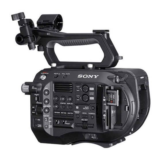
1. Overview Location and Function of Parts accurately, use this hook as a reference point. You Attaching the accessory shoe Left Side, Front Side, and Handle can attach the end of a tape measure to the hook to measure the distance from the subject. Lift the front edge of the shoe spring, and pull WB SET (white balance set) button the spring in the opposite direction to the... - Page 5 1. Overview: Location and Function of Parts Removing the accessory shoe Attaching the handle connector protective cap Top Side (supplied) Remove the show spring as described in step 1 in “Attaching the accessory shoe” (page 4) unscrew When using the camcorder with the handle the four screws, and remove the accessory shoe.
- Page 6 1. Overview: Location and Function of Parts ND/IRIS dial SHUTTER button (page 33) Right Side The ND dial operates when the ND/IRIS switch WHT BAL (white balance memory select) is set to the ND position. The IRIS dial operates switch (page 34) when the ND/IRIS switch is set to the IRIS position.
- Page 7 1. Overview: Location and Function of Parts Internal microphone (page 35) Card Slot, Rear Side, and Terminals Viewfinder Narration microphone for recording ambient sound. For details about attaching the viewfinder INPUT1 (audio input 1) connector (supplied) and eyepiece, see page 15. (page 35) INPUT2 (audio input 2) connector (page 35)
- Page 8 1. Overview: Location and Function of Parts Viewfinder Hood Grip Remote Control Infrared Remote Control Extension Unit (Option) For details about attaching the viewfinder hood For details about attaching the grip remote control For details about attaching an extension unit (supplied), see page 17.
-
Page 9: Screen Display
1. Overview Screen Display memory cards. Viewfinder Screen Display Meaning Picture cache recording External RAW output format indicator (page 39) Picture cache standby Cache During shooting (recording/standby) and playback, the camcorder status and settings are superimposed Timecode external lock indicator on the image displayed in the viewfinder. - Page 10 1. Overview: Screen Display SDI output control status indicator Zoom position indicator Information Displayed on the Screen During Playback (page 76) Displays the zoom position in the range 0 (wide angle) to 99 (telephoto) (if a lens that supports White balance mode indicator (page 34) zoom setting display is attached).
- Page 11 1. Overview: Screen Display System Status screen Assignable Button Status screen Status Screen Display item Description Focal Length Focal length value obtained Displays the video signal settings. Displays the functions assigned to each of the from the lens assignable buttons. You can check the settings and status of the Display item Description...
- Page 12 1. Overview: Screen Display Battery Status screen Rec Button Settings Screen Display item Description Media A remaining Displays an estimate of the Displays information about the battery and DC IN Displays the settings of the record START/ recording time remaining recording time of source.
-
Page 13: Preparation
You can use a battery pack or AC power supply in the System menu. Icon Remaining capacity from an AC adaptor. 91% to 100% For safety, use only the Sony battery packs and AC 71% to 90% adaptors listed below. Using AC Power 51% to 70% Lithium-ion battery packs... - Page 14 2. Preparation: Power Supply voltage is too low. If this occurs, the AC adaptor may be faulty. Check the AC adaptor, as required. Changing the warning levels The DC Low Voltage1 level is set to 11.5 V and the DC Low Voltage2 level is set to 11.0 V by factory default.
-
Page 15: Attaching Devices
2. Preparation Attaching Devices Clamp Lever Operation Clamp lever Operate the clamp levers when attaching/ removing or adjusting the position of the microphone and viewfinder. When attaching, turn the clamp lever clockwise to secure the rod. When removing or adjusting the position, turn the Clamp lever clamp lever counterclockwise to loosen the clamp lever. - Page 16 2. Preparation: Attaching Devices is facing the subject. Setting the MIRROR switch [Tip] Square-shaped clamp spacer Attaching the Eyepiece A circular-shaped spacer is attached by factory default. (page 38) to the B/T position flips the left and right sides of the image on the LCD screen, but Square mark Changing the clamp spacer the image is recorded in the correct orientation.
- Page 17 [Tip] towards you, and then pull up to open the hood. For details about lenses supported by the camcorder, contact your Sony service representative. Open the eyepiece upwards when the lock Attaching an E-mount lens disengages. The viewfinder is directly visible when the eyepiece is opened.
- Page 18 2. Preparation: Attaching Devices [Notes] Align the lens mount mark (white) with the Connect the grip remote control cable to the ˎ When removing a lens, align the mount mark on the lens ˎ camcorder, carefully insert the lens, and slowly REMOTE connector on the camcorder.
- Page 19 2. Preparation: Attaching Devices Adjusting the Position of the Align the protrusion on the arm with the groove in the grip attachment point, and Shoulder Pad secure in position using the screw removed in step 1. You can slide the shoulder pad forward or backward.
-
Page 20: Setting The Clock
2. Preparation Setting the Clock The initial settings screen appears in the viewfinder the first time the camcorder is turned on or after the backup battery has become completely discharged. Set the date and time of the internal clock using this screen. -
Page 21: Configuring Basic Camcorder Operation
(DCIP3). ˎ S-Gamut3/SLog3: Wide color gamut, for ˎ compatibility with future standard gamuts, optimized using Sony image distortion correction technology. You can select the color gamut using Base Setting (page 69) >Color Space in the System menu. -
Page 22: Using Xqd Memory Cards
M-series XQD memory cards 29.97P G-series XQD memory cards The use of memory cards other than Sony XQD memory cards is not guaranteed. 23.98P [Tip] For details about using XQD memory cards and usage precautions, refer to the operating instructions for the XQD memory S&Q (HFR mode) 59.94P... - Page 23 2. Preparation: Using XQD Memory Cards Inserting XQD Memory Cards Switching Between XQD Memory Format XQD G XQD N Discontinued XQD S XQD M XQD H Cards (EB Stream) XQD S (non EB Stream) Press the media cover release button XAVC-L 1920×1080 S&Q (HFR mode) 59.94P...
- Page 24 2. Preparation: Using XQD Memory Cards If formatting fails [Note] Up to approximately 600 clips can be recorded on one XQD memory card. Protected XQD memory cards and memory cards If the number of recorded clips reaches the limit, the not supported by the camcorder cannot be remaining recording time indicator becomes “0”...
-
Page 25: Using A Utility Sd Card
2. Preparation Using a UTILITY SD Card You can save camera configuration data for the inserting/ejecting the card. To use an SD card formatted on the camcorder in camcorder on an SD card (available separately). the slot of another device Saved data files can be imported from the SD card. -
Page 26: Using The Xdca-Fs7
2. Preparation Using the XDCA-FS7 You can add functions to the camcorder, such Switching the Timecode Input/ Align the protrusions of the XDCA-FS7 with as a V-shoe battery or external sync signal, by the left and right grooves of the camcorder Output attaching an XDCA-FS7 Extension Unit (option) to and slide all the way in, then slide the XDCA-... -
Page 27: Using An Hxr-Ifr5 And Axs-R5
2. Preparation Using an HXR-IFR5 and AXS-R5 You can record RAW video (page 39) to an AXSR5 RAW Recorder (option) using an HXR-IFR5 Interface Unit (option) and an XDCA-FS7 (option). For details about setting up the HXR-IFR5 and AXS-R5, refer to the HXR-IFR5 operation manual. Connecting the HXR-IFR5 to the Camcorder Attach the XDCA-FS7 to the camcorder... -
Page 28: Using The Infrared Remote Control
2. Preparation Using the Infrared Remote Control When Using for the First Time Changing the Battery of the Remote Control Pull out the insulating sheet from the battery holder when using the supplied infrared remote The remote control uses a standard CR2025 control for the first time. -
Page 29: Using Wi-Fi Remote Control
2. Preparation Using Wi-Fi Remote Control You can operate the camcorder from a web Playback screen Assign screen Playback screen browser by connecting a smartphone, tablet, or ˎ Status display ˎ other device that supports a web browser to the ˎ... -
Page 30: Shooting
000 30 3. Shooting Basic Operation Procedure Basic shooting is conducted using the following 4096×2160 24.00P, 4096×2160 23.98P, Recording Continuously by Changing Changing the Settings of the Record procedure. 3840×2160 59.94P, 3840×2160 29.97P, Memory Cards (Relay Rec) START/STOP Buttons on the 3840×2160 23.98P, 1920×1080 59.94P XAVC-L Attach the necessary devices, and check that... - Page 31 3. Shooting: Basic Operation Procedure Focusing using magnified view (Focus Magnifier) Adjusting focus using the focus assist indicator Adjusting the Focus Manually Rec Button Set Buttons and memory cards By factory default, the Focus Magnifier x4/x8 Focus detection window “Rec Button [SlotB] The record START/STOP function is assigned to the ASSIGN 4 button on the (Focus area marker)
- Page 32 3. Shooting: Basic Operation Procedure Switching Between XQD Memory Cards When two XQD memory cards are inserted, press the SLOT SELECT button (page 6) to switch cards. [Note] You cannot switch between memory cards during playback mode. Also, continuous playback of a clip spanning media in slot A and slot B is not supported.
-
Page 33: Changing Basic Settings
3. Shooting Changing Basic Settings You can change the settings based on the video [Note] Temporarily adjusting the iris automatically GAIN switch (I). The gain cannot be adjusted in Cine EI mode. Also, the application or recording conditions. This is useful when you want to adjust the Press and hold the PUSH AUTO IRIS button (F) to brightness cannot be adjusted automatically using the iris or exposure by one step without changing the depth... - Page 34 3. Shooting: Changing Basic Settings Adjusting in preset mode Temporarily adjusting the iris automatically Examples: Adjusting for Natural Colors (White – When a single color dominates the subject, such as sky, You can assign Push Auto ND to an assignable Set the PRESET/VARIABLE switch (B) to the PRESET sea, ground, or flowers.
- Page 35 If the INPUT1/INPUT2 connectors, respectively. error message persists after repeated attempts to set the setup menu. white balance, contact your Sony service representative. ˎ For CH3/CH4, set Audio Input >CH3 Level ˎ Connected device...
-
Page 36: Useful Functions
3. Shooting Useful Functions ˎ VF Mode ˎ position indicator, iris position indicator, and zoom Assignable Buttons/Dials Slow & Quick Motion position indicator are all turned off. ˎ ND Filter Position ˎ ˎ IRIS ˎ NTSC Area ˎ AGC ˎ There are ten assignable buttons (page 6, When the video format (page 70) is set to one ˎ... - Page 37 3. Shooting: Useful Functions ˎ Interval Rec mode is automatically released after changing ˎ To exit Interval Rec mode Recording menu. Recording Video Intermittently system settings, such as the video format. ˎ Interval Rec settings cannot be changed during recording ˎ...
- Page 38 3. Shooting: Useful Functions starts and video is written to XQD memory cards [Note] Rec Review is not supported if the video format is changed starting from the video stored in the cache after recording a clip. memory. The image is not inverted. To cancel Picture Cache Rec Self Portrait Mode Set Picture Cache Rec >Setting in the Recording...
- Page 39 3. Shooting: Useful Functions the peaking type and peaking frequency using ˎ While using the GPS function, gripping the handle may ˎ Shooting in Cine EI Mode affect the positioning accuracy. Peaking (page 62) in the VF menu. Positioning Display GPS reception state status This mode mimics the way a film camera works,...
- Page 40 3. Shooting: Useful Functions PAL Area adaptor to perform adjustments. Set Codec >Select in the System menu to [Notes] RAW. Codec >Select setting RAW output formats ˎ If Audio Input >CH3 Level and CH4 Level in the Audio ˎ Selecting RAW & XAVC-I will simultaneously RAW / RAW &...
-
Page 41: Connecting A Tablet Or Other Devices Using
For details about the Content Browser Mobile application, enabled Devices (Using IFU-WLM3 Connect the CBK-WA100 USB cable to the USB contact your Sony sales or service representative. Attach the CBK-WA100 to the mounting wireless LAN module connector (1), and the Only) bracket, and tighten the two screws. - Page 42 3. Shooting: Connecting a Tablet or Other Devices using Wireless LAN The various settings will vary depending on the device. For details, refer to the instruction manual for the device. Touch the camcorder using the device. The device connects to the camcorder, launches a web browser, and displays the Wi-Fi remote control.
-
Page 43: Displaying The Wi-Fi Remote Control
3. Shooting Displaying the Wi-Fi Remote Control The Wi-Fi Remote screen is automatically resized to match the screen size of the connected device. Connect the camcorder and device using a Wireless LAN connection (page 41). Launch a browser on the device and enter “http://IP address of camcorder (Wi-Fi >IP Address in System menu)/rm.html”... -
Page 44: Thumbnail Screen
000 44 4. Thumbnail Screen Thumbnail Screen The thumbnail screen appears if you press the THUMBNAIL button (page 6). The thumbnail screen displays the clips stored on XQD memory cards as thumbnails (index pictures). You can select a clip on the thumbnail screen and start playback of that clip. The playback image can be displayed in the viewfinder and on an external monitor. Pressing the THUMBNAIL button again closes the thumbnail screen and returns to the camera image. -
Page 45: Playing Clips
4. Thumbnail Screen Playing Clips Playing Recorded Clips You can play recorded clips when the camcorder is in recording standby (Stby) mode. Insert an XQD memory card for playback. Press the THUMBNAIL button. Turn the SEL/SET dial (page 6) to move the cursor to the thumbnail for the clip you want to play. -
Page 46: Clip Operations
4. Thumbnail Screen Clip Operations On the thumbnail screen, you can operate the Displaying the essence mark thumbnail screen All Clips: clips or check clip properties using the thumbnail Deletes all of the displayed clips. menu. Select Thumbnail View (page 66) >Essence Mark Changing the information displayed on the The thumbnail menu (page 66) appears Thumbnail in the Thumbnail menu, and select the... -
Page 47: Menu Display And Settings
000 47 5. Menu Display and Settings Setup Menu Configuration and Hierarchy Press the MENU button to display the setup menu File menu Setup Menu Hierarchy Paint White in the viewfinder to specify various items for Contains settings related to files. Offset White shooting, recording, and playback (menu can also System menu... - Page 48 5. Menu Display and Settings: Setup Menu Configuration and Hierarchy Thumbnail Display Clip Properties System Basic Authentication Set Index Picture Wi-Fi Thumbnail View Set Shot Mark IR Remote Set Clip Flag Camera Battery Alarm Lock/Unlock Clip Camera DC IN Alarm Delete Clip Ext.
-
Page 49: Setup Menu Operations
5. Menu Display and Settings Setup Menu Operations Press the MENU button to display the setup menu the corresponding function. The character string is confirmed and the in the viewfinder to specify various items for ˎ Selecting an item that requires confirmation ˎ... -
Page 50: Setup Menu List
5. Menu Display and Settings Setup Menu List This section describes the function and settings of the items in each menu. User Factory default settings are shown in bold (for example, 18dB). Item Sub-item setting Description Format Media See Format Media in the Media menu. Format (initializes) memory cards User Menu... - Page 51 5. Menu Display and Settings: Setup Menu List Camera >ISO/Gain/EI Camera >ISO/Gain/EI Sets gain settings. Sets gain settings. Item Sub-item setting Description Item Sub-item setting Description ISO/Gain<H> When Mode is set to ISO and dynamic range is Sets the <H> gain preset value. ISO/Gain<L>...
- Page 52 5. Menu Display and Settings: Setup Menu List Camera >Auto Exposure Camera >Auto Exposure Sets automatic exposure adjustment settings. Sets automatic exposure adjustment settings. Item Sub-item setting Description Item Sub-item setting Description Level –2.0 / –1.75 / –1.5 / –1.25 / –1.0 / –0.75 / –0.5 / Sets the brightness level for the Detect / 2 / 3 / 4 / 5 / 6...
- Page 53 5. Menu Display and Settings: Setup Menu List Camera >Shutter Camera >Shutter Sets electronic shutter operating condition settings. Sets electronic shutter operating condition settings. Item Sub-item setting Description Item Sub-item setting Description Speed Mode / Angle / ECS / Off Selects the operating mode of the electronic Shutter Angle 5.6°...
- Page 54 5. Menu Display and Settings: Setup Menu List Camera >Flicker Reduce Camera >AF Micro Adjustment Sets flicker correction settings. Sets focus position micro adjustment. (Enabled when LA-EA2/4 (option) is used) Item Sub-item setting Description Item Sub-item setting Description Mode Auto / On / Sets the flicker correction mode.
- Page 55 5. Menu Display and Settings: Setup Menu List Paint Menu Paint >White Sets white balance settings. Item Sub-item setting Description Paint >White ATW Speed 1 / 2 / / 4 / 5 Sets the response speed in ATW mode. Sets white balance settings. 1: Fastest response speed Item Sub-item setting...
- Page 56 5. Menu Display and Settings: Setup Menu List Paint >Black Paint >Black Gamma Sets black settings. Sets black gamma correction settings. Item Sub-item setting Description Item Sub-item setting Description Setting On / Turns the black gamma correction function Master Black –99 to +99 (±0) Sets the master black level.
- Page 57 5. Menu Display and Settings: Setup Menu List Paint >White Clip Paint >Detail Sets white clip adjustment settings. Sets detail adjustment settings. Item Sub-item setting Description Item Sub-item setting Description Setting / Off Turns the white clip adjustment function on/ V Black Limit –99 to +99 (±0) Sets the black-side V detail limiter.
- Page 58 5. Menu Display and Settings: Setup Menu List Paint >Matrix Paint >Multi Matrix Sets matrix correction settings. Sets multi matrix correction settings. Item Sub-item setting Description Item Sub-item setting Description Adaptive / Off Turns the adaptive matrix function on/off. Setting On / Turns the multi matrix correction function Matrix...
- Page 59 5. Menu Display and Settings: Setup Menu List Audio >Audio Input Audio >Audio Input Sets audio input settings. Sets audio input settings. Item Sub-item setting Description Item Sub-item setting Description INPUT2 MIC –60dB / –50dB / –40dB Sets the reference recording level for XLR Audio Input 0 to Sets the audio input level.
- Page 60 5. Menu Display and Settings: Setup Menu List Video Menu Audio >Audio Input Sets audio input settings. Item Sub-item setting Description Video >Output On/Off CH3 Level Input without XLR adaptor Sets the combination of audio input level Sets video output settings. Audio Input Level / CH3 Input Level / adjustments enabled for recording channel Item...
- Page 61 When creating a LUT using RAW Viewer, select F55/F5 as the output format. Create the following folder on the SD card and store LUT files in the folder. \PRIVATE\SONY\PRO\CAMERA\PMWF55_F5 Look Profile LC-709 Selects the type of Look profile, when Select 2: LC-709typeA Monitor LUT >Category is set to Look Profile.
- Page 62 5. Menu Display and Settings: Setup Menu List Video >Monitor LUT VF >Peaking Sets monitor LUT settings. Available only when shooting in Cine EI mode. Sets peaking settings. Item Sub-item setting Description Item Sub-item setting Description User 3D LUT User 3D-1 Selects the type of user 3D LUT.
- Page 63 5. Menu Display and Settings: Setup Menu List VF >Marker VF >Display On/Off Sets marker display settings. Sets display item settings. Item Sub-item setting Description Item Sub-item setting Description Aspect Safety 80% / / 92.5% / 95% Selects the size of the aspect safety zone Focus Position Meter / Feet / Off...
- Page 64 5. Menu Display and Settings: Setup Menu List VF >Display On/Off TC/UB >Timecode Sets display item settings. Sets timecode settings. Item Sub-item setting Description Item Sub-item setting Description / Off Selects the items to display in the viewfinder. Rec Run / Free Run Rec Run: Runs only when recording.
- Page 65 5. Menu Display and Settings: Setup Menu List Recording Menu Recording >Interval Rec Sets Interval Rec settings (page 37). Item Sub-item setting Description Recording >S&Q Motion Number of 1frame / 2frames / 3frames / 6frames / 9frames Sets the number of frames to record per take Sets Slow &...
- Page 66 5. Menu Display and Settings: Setup Menu List Recording >SDI/HDMI Rec Control Thumbnail >Set Shot Mark Sets SDI/HDMI recording control settings. Sets shot mark settings. Item Sub-item setting Description Item Sub-item setting Description Setting On / Turns recording start/stop control for an Delete Shot Deletes Shot Mark1.
-
Page 67: Media Menu
5. Menu Display and Settings: Setup Menu List Thumbnail >Customize View Media >Clip Switches the thumbnail screen view. Sets settings related to clip names. Item Sub-item setting Description Item Sub-item setting Description Thumbnail Date Time / Time Code / Duration / Sequential Switches the information displayed below Auto Naming Cam ID + Reel# /... - Page 68 Description card. Load SD Card Execute / Cancel Loads User menu settings on an SD card into PRIVATE\SONY\PRO\CAMERA\PMWF55_F5 internal memory. Reset / 2 / 3 / 4 / 5 / 6 / All Resets the monitor LUT data in internal Execute: Load settings memory to default values.
- Page 69 [Note] Place files in the following folders on the SD card. ALL files, Scene files, User Menu Item: \PRIVATE\Sony\PRO\CAMERA\PXW-FS7M2 User gamma files: \PRIVATE\Sony\PRO\CAMERA\HD_CAM Monitor LUT files, monitor 3D LUT files: \PRIVATE\Sony\PRO\CAMERA\PMWF55_F5...
- Page 70 5. Menu Display and Settings: Setup Menu List System >Rec Format System >Rec Format Sets recording format settings. Sets recording format settings. Item Sub-item setting Description Item Sub-item setting Description Video Format Sets the recording format. RAW Output Sets the recording format for an external Format RAW recorder.
- Page 71 5. Menu Display and Settings: Setup Menu List System >Assignable Button System >Assignable Button Sets function assignments to assignable buttons. Sets function assignments to assignable buttons. Item Sub-item setting Description Item Sub-item setting Description <1> to <10> Off / Marker / Zebra / Peaking / Video Signal Assigns functions to assignable buttons.
- Page 72 5. Menu Display and Settings: Setup Menu List System >Assignable Button System >ND Dial Sets function assignments to assignable buttons. Sets the direction of rotation of the ND dial. Item Sub-item setting Description Item Sub-item setting Description <1> to <10> Clip Flag OK: ND Dial Normal...
- Page 73 SET: Set the value. Select Sets the display language. SET: Set language. Password Password Sets a password (1 to 16 alphanumeric (pxw-fs7m2) characters). System >Clock Set SET: Set the value. Sets internal clock settings. System >Wi-Fi Item Sub-item setting Description Sets wireless LAN connection settings.
- Page 74 Sets battery low-voltage alarm settings. If a battery is connected to the XDCA-FS7, Item Sub-item setting Description “Info Battery,” “Sony Battery,” or “Other Battery” is displayed. If a DC source is Low BATT 5% / / 15% / … / 45% / 50% Sets the remaining battery level to display a connected, “DC IN”...
- Page 75 5. Menu Display and Settings: Setup Menu List System >APR Executes APR. Item Sub-item setting Description Execute / Cancel Runs APR (Automatic Pixel Restoration) for image sensor auto adjustment. Execute: Run [Note] Always attach the lens cap before running APR. System >Camera Config Sets down-converter output settings.
-
Page 76: External Device Connection
000 76 6. External Device Connection Connecting External Monitors and Recording Devices To display recorded/playback pictures on an [Notes] ˎ If a connected external device does not support a REC ˎ external monitor, select the camcorder output trigger signal, the device cannot be operated. signal and use an appropriate cable for the ˎ... -
Page 77: External Synchronization
6. External Device Connection External Synchronization When shooting using multiple camcorder units, For PAL Area The timecode generator of the camcorder acquires Check that the TC IN/OUT switch (page 8) the camcorders can be synchronized to a specific lock with the reference timecode, and “EXT-LK” of the XDCA-FS7 is set to the OUT position, Frame rate of Supported input reference... -
Page 78: Managing/Editing Clips Using A Computer
6. External Device Connection Managing/Editing Clips using a Computer – Disconnecting the USB cable Connecting Using a USB Cable ˎ Operation is not guaranteed to work on all computers. ˎ Using nonlinear editing systems Using an XQD card reader (option) In a nonlinear editing system, editing software (option) that supports the formats recorded by the Connect an MRW-E80 XQD Card Reader (option) -
Page 79: Appendix
Periodic inspections are recommended to keep the unit working properly and to prolong its usable lifetime. Contact a Sony service or sales representative for more information about inspections. -
Page 80: Nd Filter Dial
Only use this procedure if the ND filter will not move. The ND filter may become damaged if this procedure is used during normal operation. ˎ After the procedure above is used, consult a Sony service ˎ center to have the camcorder repaired. -
Page 81: Output Formats And Limitations
7. Appendix Output Formats and Limitations Factory default settings are shown in bold (for example, 2048×1080P (Level A)). Recording format SDI/HDMI output settings SDI output signal HDMI output signal settings (Output Format >SDI and HDMI [Notes] (Rec Format >Video in the Video menu) ˎ... - Page 82 7. Appendix: Output Formats and Limitations Recording format SDI/HDMI output settings SDI output signal HDMI output signal Recording format SDI/HDMI output settings SDI output signal HDMI output signal settings (Output Format >SDI and HDMI settings (Output Format >SDI and HDMI (Rec Format >Video in the Video menu) (Rec Format >RAW...
- Page 83 7. Appendix: Output Formats and Limitations When Country >NTSC/PAL Area in the System menu is set to PAL Area Recording format SDI/HDMI output settings SDI output signal HDMI output signal settings (Output Format >SDI and HDMI (Rec Format >RAW in the Video menu) Output Format and When using basic configuration (XAVC-I / XAVC-L / MPEG HD) HDMI...
- Page 84 7. Appendix: Output Formats and Limitations When using extension unit (RAW) Recording format SDI/HDMI output settings SDI output signal HDMI output signal settings (Output Format >SDI and HDMI Recording format SDI/HDMI output settings SDI output signal HDMI output signal (Rec Format >Video in the Video menu) settings (Output Format >SDI and HDMI...
- Page 85 7. Appendix: Output Formats and Limitations HDMI Output Settings for HDMI Target Devices Recording format SDI/HDMI output settings SDI output signal HDMI output signal settings (Output Format >SDI and HDMI (Rec Format >RAW in the Video menu) Output Format and HDMI Output Setting >HDMI Output Display >SDI/HDMI in the Video menu...
- Page 86 7. Appendix: Output Formats and Limitations Output Menu Settings and Video Output Color Space when Preset Select is BT.2020 The color space of recorded video is BT.2020 when Matrix >Preset Select in the Paint menu is set to BT.2020. The color space of the video output varies as follows, depending on the Output Format and Output Color Space settings.
-
Page 87: Error/Warning Messages
If the error persists when the camcorder is turned on again, contact your Sony service representative. The following caution and operation messages may appear in the center of the screen. Follow the (If the camcorder does not turn off when the POWER instructions provided to resolve the issue. - Page 88 For details, refer to the operating instructions for the memory card. Fan Stopped The built-in fan stopped. Avoid use at high temperatures, disconnect the power, and contact your Sony service representative. Invalid setting value was reset: The Clip Naming format setting was reset because an invalid ALL Media/Clip Naming/Camera Position file was loaded.
-
Page 89: Items Saved In Files
7. Appendix Items Saved in Files Yes: Item is saved. LEVEL 1 LEVEL 2 LEVEL 3 All File Scene File No: Item is not saved. Camera Flicker Reduce Mode LEVEL 1 LEVEL 2 LEVEL 3 All File Scene File Frequency Camera ISO/Gain/EI Mode... - Page 90 7. Appendix: Items Saved in Files LEVEL 1 LEVEL 2 LEVEL 3 All File Scene File LEVEL 1 LEVEL 2 LEVEL 3 All File Scene File Paint Black Setting Paint Skin Detail Setting Master Black Area Detection – – R Black Area Indication B Black Level...
- Page 91 7. Appendix: Items Saved in Files LEVEL 1 LEVEL 2 LEVEL 3 All File Scene File LEVEL 1 LEVEL 2 LEVEL 3 All File Scene File Audio Audio Input CH1 Input Select Video Output On/Off CH2 Input Select HDMI CH3 Input Select Output Format CH4 Input Select HDMI...
- Page 92 7. Appendix: Items Saved in Files LEVEL 1 LEVEL 2 LEVEL 3 All File Scene File LEVEL 1 LEVEL 2 LEVEL 3 All File Scene File Marker Setting Display On/Off Focus Mode Color Focus Area Indicator Center Marker Focus Area Ind. (Push AF) Safety Zone Focus Indicator Safety Area...
- Page 93 7. Appendix: Items Saved in Files LEVEL 1 LEVEL 2 LEVEL 3 All File Scene File LEVEL 1 LEVEL 2 LEVEL 3 All File Scene File Recording S&Q Motion Setting Media Update Media Media(A) – – High Frame Rate Mode Media(B) –...
- Page 94 DC Low Voltage2 Assignable Dial Direction Ext. Unit Battery Alarm Near End:Info Battery IRIS Dial Direction End:Info Battery ND Dial ND Dial Direction Near End:Sony Battery Rec Lamp Rec Lamp End:Sony Battery Fan Control Setting Near End:Other Battery HOLD Switch Setting...
-
Page 95: Block Diagrams
7. Appendix Block Diagrams See related items in “Setting the Audio to Record” (page 35) and “Setup Menu List” (page 50). Audio Input (CH3&CH4) Audio Input (CH1&CH2) * Set to Manual when audio is input from XLR adaptor. * Set to MAN when audio is input from XLR adaptor. - Page 96 7. Appendix: Block Diagrams Audio Output...
-
Page 97: Updating E-Mount Lens Software
7. Appendix Updating E-mount Lens Software You can update the software of an E-mount lens Select Execute. using the camcorder. The version update preparation begins. When Refer to the web site for the lens for lenses that preparation is completed, a confirmation can be updated and the corresponding firmware. -
Page 98: Licenses
GPL/LGPL. authorized to do so by SONY. You may not remove, Notwithstanding the foregoing, any software in The source code is provided on the internet. the SOFTWARE having a separate end user license... - Page 99 SOFTWARE may be provided by third parties over You acknowledge and agree that use of the referred to as “SONY”) SHALL NOT BE LIABLE FOR ANY administering the functionalities of the SOFTWARE; which SONY has no control. USE OF THE CONTENT...
- Page 100 SONY may also such time as you interact with SONY’ s or third parties’ take any legal and technical remedies to prevent servers, or otherwise. Such updates or modifications...
-
Page 101: Specifications
7. Appendix Specifications XAVC Long Recording/playback time (using QD-G128E) ProRes 422 HQ General AVC/H.264 High Profile XAVC Intra 59.94i/29.97P QFHD: VBR, 150 Mbps (max), 4096×2160/3840×2160 Approx. 60 minutes 4:2:0 Long 59.94P 50i/25P Mass Approx. 2.0 kg (4 lb 6.5 oz) (body only) HD: VBR, 50 Mbps (max), Approx. - Page 102 7. Appendix: Specifications Lens mount Built-in speaker Battery charger (BC-U1) E-mount (lever lock type) Monaural Dedicated (40-pin) Power requirements: 100 V to 240 V AC, Latitude Internal microphone 50 Hz/60 Hz 14-stop Monaural Power consumption: 38 W Video S/N Rated output: Charging 16.4 V, 1.9 A/1.5 A Display Section 57 dB (Video Gamma/Noise Suppression: off) Power cord (2)
- Page 103 7. Appendix: Specifications Software Downloads Trademarks ˎ SONY WILL NOT BE LIABLE FOR THE LOSS, ˎ ˎ SONY WILL NOT BE LIABLE FOR DAMAGES OF ˎ ANY KIND RESULTING FROM A FAILURE TO REPAIR, OR REPRODUCTION OF ANY DATA IMPLEMENT PROPER SECURITY MEASURES...
Need help?
Do you have a question about the PXW-FS7M2 and is the answer not in the manual?
Questions and answers