Hammond XK-5 Owner's Manual
Hide thumbs
Also See for XK-5:
- Reference manual (344 pages) ,
- Owner's playing manual (174 pages) ,
- Owner's manual (170 pages)
Table of Contents
Advertisement
Quick Links
Model:
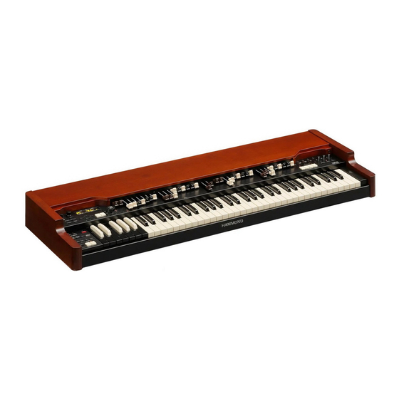
Th ank you, and congratulations on your choice of the Hammond Draw-
bar Keyboard XK-5.
Th e XK-5 Drawbar Keyboard is condensed the sound and playability of
the legendary Hammond Tone Wheel organ.
Please take the time to read this manual completely to take full advantage
of the many features of your XK-5; and please retain it for future refer-
ence.
UPPER
PEDAL
LOWER
BANK KEY
PATCH
Owner s Manual
Advertisement
Table of Contents

Related Manuals for Hammond XK-5


Summary of Contents for Hammond XK-5
- Page 1 Th e XK-5 Drawbar Keyboard is condensed the sound and playability of the legendary Hammond Tone Wheel organ. Please take the time to read this manual completely to take full advantage of the many features of your XK-5; and please retain it for future refer- ence. UPPER...
-
Page 2: Important Safety Instructions
IMPORTANT SAFETY INSTRUCTIONS Read these instructions. Only use attachments/accessories specifi ed by the manufacturer. Keep these instructions. Use only with the cart, stand, tripod, bracket, or table specifi ed by the manufacturer, or sold Heed all warnings. with the apparatus. When cart is used: use cau- tion when moving the cart/apparatus combi- Follow all instructions. - Page 3 If the fuse cover is lost, the plug must not be used until a replacement cover is obtained. A replacement fuse cover can be obtained from your local Hammond Dealer. IF THE FITTED MOULDED PLUG IS UNSUITABLE FOR THE SOCKET OUTLET IN YOUR HOME, THEN THE FUSE SHOULD BE REMOVED AND THE PLUG CUT OFF AND DISPOSED OF SAFELY.
-
Page 4: Important - Please Read
Unfortunately, it may be impossible to restore the contents of data that was stored in another MIDI device (e.g., a se- Placement quencer) once it has been lost. Hammond assumes no li- Using the unit near power amplifi ers (or other equipment ability concerning such loss of data. -
Page 5: Introduction
INTRODUCTION... -
Page 6: Table Of Contents
Table Of Contents USING CONTROLLERS ................32 EXPRESSION PEDAL ..................32 FOOT SWITCH ....................32 IMPORTANT SAFETY INSTRUCTIONS ..........2 LESLIE MODE SWITCH ................32 IMPORTANT - PLEASE READ ..............4 TEMPORARY EQUALIZING (MASTER EQUALIZER) ......33 TRY TO MAKE YOUR OWN SOUND ...........34 INTRODUCTION ......5 SELECT [B] PRESET KEY ................34 Column: Initializing Adjust Presets ............34 MAIN FEATURES .................. - Page 7 OPERATION IN THIS MODE ...............59 MATCHING TRANSFORMER ................92 OVERDRIVE ......................92 MENU MODE ...................60 MULTI-EFFECTS ....................93 HOW TO READ THE DISPLAY ..............60 EQUALIZ (Equalizer) ................100 OPERATION IN THIS MODE ...............60 PATCH EQUALIZER ..................100 MENU AND THE CONTENTS ..............61 PATCH EQUALIZER AND MASTER EQUALIZER ........100 FUNCTION MODE ..................62 REVERB ....................
- Page 8 SAVE THE SETUP ....121 MIDI CHANNEL AND MESSAGE ............. 153 SPECIFICATIONS .................. 154 SAVE YOUR SETUP ................122 SERVICE ....................157 WHAT YOU CAN DO WITH THE USB FLASH DRIVE ......122 ABOUT USB FLASH DRIVE ..............122 USABLE USB FLASH DRIVE ................. 122 USB CONNECTOR ..................
-
Page 9: Main Features
XLK-5 and the Pedal Keyboard XPK-250. USB COMPATIBILITY Th e XK-5 has both USB “A” and “B” ports. Th e “A” port (“USB to Host”) enables easy System, MIDI, and Audio Communications with your Computer. Th e “B” port allows Backups and Software Upgrades which are simple procedures, using common USB ‘Flash’... -
Page 10: Names And Functions
NAMES AND FUNCTIONS TOP PANEL ❽ UPPER PEDAL LOWER ❹ ❶ ❾ BANK KEY PATCH ❷ ❻ ❼ ❸ ❺ UPPER LEFT RECORD button ❶ MASTER VOLUME knob Records a Patch, Favorite, or Leslie cabinets etc. (P. 38) PRESET KEYS Controls the entire volume. - Page 11 VIBRATO AND CHORUS PERCUSSION UPPER button ON button Switches the Vibrato & Chorus eff ect on the Upper part. (P. 47) Adds percussion (decay) to the UPPER part. (P. 46) LOWER button SOFT button Switches the Vibrato & Chorus eff ect on the Lower part. (P. 47) Switches the percussion volume.
-
Page 12: Recess
12 NAMES AND FUNCTIONS - continued REVERB ON button Switches the Reverb eff ect. (P. 50) REVERB DEPTH knob Adjusts the depth of the Reverb eff ect. (P. 50) KEYBOARD KEYBOARD 61 notes of musical keys, 12 notes of Preset keys, water-fall type, non-weighted, virtual multi-contact keyboard. -
Page 13: Rear Panel
Receives performance information. Th is jack receives specifi ed LESLIE 11 PIN jack MIDI channels. Also, use to connect the Hammond XLK-3 or Connects the Leslie speaker system. (P. 18) generic MIDI keyboard as used as Lower or Upper part regard- less MIDI channel by the confi guration. - Page 14 Owner’s Manual...
-
Page 15: Hook-Up
HOOK-UP... -
Page 16: Basic Hook-Up
BASIC HOOK-UP Attach cables and accessories as illustrated. Th ere is no on-board amplifi cation or speaker system. An external amp/speaker is required. When the stereo headphones are connected to the HEADPHONES jack, you can enjoy playing privately. Switch this keyboard, and any external equipment OFF before connecting amps or headphones. -
Page 17: Connecting The Controllers
CONNECTING THE CONTROLLERS CONNECTING THE EXPRESSION PEDAL USING EXP-100F 1. Connect the EXP-100F to the “EXP. PEDAL” jack. 2. Set the CONTROL - EXP. SOURCE at “EXP. PEDAL” or “BOTH” (P. 73 #4). UPPER PEDAL LOWER BANK KEY PATCH USING EXP-50/20 1. -
Page 18: Connecting The Leslie Speaker
2. Set the keyboard channel - UPPER and the Leslie MIDI channel to the same channel (P. 118). When this unit detects that the Leslie speaker is connected, the Leslie parameters sent through MIDI from this unit are switched from the XK-5 original to those for the Leslie speaker. Owner’s Manual... -
Page 19: Connecting The 1 Channel Leslie Speaker
CONNECTING THE 1 CHANNEL LESLIE SPEAKER UPPER PEDAL LOWER BANK KEY PATCH Using with stationary speakers UPPER PEDAL LOWER BANK KEY PATCH BASIC CONNECTION OF THE LESLIE SPEAKER STATIONARY SPEAKER The word “Stationary Speaker” means ordinary Connect the Leslie Speaker #981/#3300/#122XB and the Leslie 11-PIN jack on this no rotating speaker. -
Page 20: Expand The Keyboard
EXPAND THE KEYBOARD Th is instrument can be upgraded to dual keyboards by connecting an external keyboard and pedalboard. 3 KEYBOARDS (USING XLK-5 AND XPK-250) HEAD CU-1 PHONES TO KEYBOARD PEDAL XLK-5 CU-1 XPK-250 1. Hook-up as illustrated above. NOTE: This illustration shows only the keyboard expansion See P. 16 for the basic hook up of the power source, audio, etc. -
Page 21: Keyboards (Using Midi Keyboards)
PER” (P. 118 #2). Refer to the operation manual of the MIDI keyboards, as required. RECOMMENDABLE MIDI KEYBOARD Th e following HAMMOND MIDI keyboards (compliant with the XK-5) are available from our sales dealers: Lower keyboard unit XLK-3, XLK-B3 MIDI pedalboard XPK-100 (13 keys) -
Page 22: Manuals (With Xlk-5)
22 EXPAND THE KEYBOARD - continued 2 MANUALS (WITH XLK-5) Regardless MIDI jack or templates. HEAD CU-1 PHONES TO KEYBOARD PEDAL CU-1 XLK-5 1. Hook up illustrated as above. NOTE: This illustration shows only the keyboard expansion See P. 16 for the basic hook up of the power source, audio, etc. -
Page 23: Manuals (With Midi Keyboard)
2 MANUALS (WITH MIDI KEYBOARD) UPPER UPPER PEDAL PEDAL LOWER LOWER BANK KEY BANK KEY PATCH PATCH Use Expression cable on Use Expression cable on XLK-3 and XLK-B3. XLK-3 and XLK-B3. MIDI Keyboard MIDI Keyboard MIDI OUT MIDI OUT 1. Hook-up as illustrated above. NOTE: This illustration shows only the keyboard expansion See P. -
Page 24: Manual + Pedalboard (With Midi Pedalboard)
EXPAND THE KEYBOARD - continued 1 MANUAL + PEDALBOARD (WITH MIDI PEDALBOARD) UPPER PEDAL LOWER BANK KEY PATCH MIDI Pedalboard 1. Hook-up as illustrated above. NOTE: This illustration shows only the keyboard expansion See P. 16 for the basic hook up of the power source, audio, etc. -
Page 25: Power On And Play
POWER ON AND PLAY... -
Page 26: Power On
HOW TO POWER ON After making the necessary connections, follow the procedures below for powering on your XK-5. Please be sure to adhere to the procedure, to prevent malfunction or damage. PROCEDURES 1. Before switching the power ON, set the [MASTER VOLUME] knob to minimum. -
Page 27: Play With The Patches
PLAY WITH THE PATCHES Recall the 200 “PATCHES” recorded in this unit using the VALUE knob and then play. WHAT IS “ PATCH”? Th e Hammond XK-5 has, in addition to Drawbar set- Lower U99 Upper U99 tings, many ways to customize and tailor those settings. -
Page 28: Play With Preset Keys
PLAY WITH PRESET KEYS Play with “Patches” which assigned on the Preset Keys. WHAT ARE “PRESET KEYS”? Th e Preset Keys are the key group which select the Patches (var- Bank A ious setting) quickly, a Preset Key assigned a Patch. Bank ~ Upper Preset Key NOTE: It explained on “Favorites”... -
Page 29: Assign Favorite Patches (Favorites)
You can record in the Preset Key [C] on the XK-5, but it makes no sounds when you select Th e Preset Keys of this keyboard works as they do on recent Hammond organs. this Preset Key at the factory setting. -
Page 30: Switching Favorite On And Off
ASSIGN FAVORITE PATCHES (FAVORITES) - continued SWITCHING FAVORITE ON AND OFF 1. LOCATE THE MENU MODE 4. LOCATE THE PRESET KEY PAGE UPPER PEDAL LOWER UPPER PEDAL LOWER BANK KEY PATCH BANK KEY PATCH Press the [MENU/EXIT] to display the menu. If the display shown does not match the illustration, press it again. -
Page 31: Assign A Patch To A Preset Key
ASSIGN A PATCH TO A PRESET KEY Assignment Patches to the 100 Preset Bank/Key (“C-C” to “A-A”, except A and B) regarding your playlist or changing scene in the song. 1. SWITCH ON THE FAVORITE Switch the Favorite “On” refer to the previous page. 2. -
Page 32: Using Controllers
EXPRESSION PEDAL Th e Expression Pedal controls the overall volume or loudness of the XK-5. Th e further you depress the pedal, the louder the sound becomes; the more you pull back on the pedal, the softer it. NOTE: The Expression pedal has specifi c parameters to adjust. (P. 73) -
Page 33: Temporary Equalizing (Master Equalizer)
Every room has a diff erent acoustic profi le, and it is often necessary to compensate for this. Th e XK-5’s Master Equalizer allo ws you to tailor the overall tonal profi le of your instrument without changing the contents of the Patches. -
Page 34: Try To Make Your Own Sound
UPPER PEDAL LOWER BANK KEY PATCH Go to the page F by pressing [ ] button at 5 times. Th e item DEFAULT will selected. Press the [PLAY] button. Th is returns the XK-5 to the Play mode. Owner’s Manual... -
Page 35: Pull Out The "B" Drawbars
Organ terms: Upper, Lower, and Pedal. Th ese parts can be individually played with diff erent sounds. Th e Upper keyboard was called “Swell” came from the pipe organ. Th e XK-5 has a single keyboard. Plural parts are available simultaneously, by splitting the keyboards or expanding them using a MIDI keyboard. -
Page 36: Add Effects
TRY TO MAKE YOUR OWN SOUND - continued ADD EFFECTS VIBRATO AND CHORUS Adding the Classic Hammond Vibrato & Chorus to the sound. [UPPER], [LOWER] buttons UPPER PEDAL LOWER Switches the Vibrato & Chorus eff ect ON(LED lit)/OFF. BANK KEY... -
Page 37: Split - Divide The Keyboard By Parts
NOTE: The Pedal To Lower can be set to play in Lowest, Polyphonic, and Chord modes (P. 116 #1). You can change the playing range of the Pedal To Lower (the upper limit) (P. 116 #2). NOTE: When the XK-5 is expanded to 2 manual, the Pedal To Lower function appears on the inverted physically LOWER keyboard (P. -
Page 38: Record The Patch To Memory
TRY TO MAKE YOUR OWN SOUND - continued RECORD THE PATCH TO MEMORY All the previous settings can be recorded to any Patch within Th e Patch can be recorded by using Preset Keys when the Fa- the range of U00 to U99. vorite is “Off ”... -
Page 39: Setting Up
SETTING UP... -
Page 40: Sound Engine Structure
SOUND ENGINE STRUCTURE Virtual Tonewheel Set Upper Keyboard Pedalboard Lower Keyboard Percussion Pedal Lower Upper Drawbars Drawbars Drawbars Pedal V&C Matching Vibrato & Chorus Transformer Exp. Upper&Lower Multi Effect Tube 1 Overdrive Tube 2 Expression (Pre) switched if Leslie on Reverb Master Reverb Leslie... - Page 41 If you want more detail, please read from following this page. TONE WHEELS Th e sound source or “engine” of the classic Hammond Organ are electro-magnetic Tone Wheel generators. On this keyboard, the Tone Wheel engine is replicated digitally. While the power is on, each of the 96 virtual Tone Wheels keeps oscillating as they did in the vintage Hammond Organs.
-
Page 42: Harmonic Drawbars
Th e Harmonic Drawbars (hereinafter, Drawbars) on this keyboard are used to create the basic “Hammond” sounds. Each Drawbar is marked with the register numbers 1 - 8 along the fl at part of the Drawbar. When the Drawbars are fully pushed in, no sound is heard;... -
Page 43: Drawbars For The Upper And Lower Parts
DRAWBARS FOR THE UPPER AND LOWER PARTS PRESET KEYS AND DRAWBARS Th ere are 2 sets of Drawbars for Upper part on the left, Lower part on the right. Use Preset Keys [A ] and [B] to engage each one. Th e operation of the Drawbars is disabled when the other Preset Key is selected, basically. -
Page 44: Drawbar Registration Patterns
HARMONIC DRAWBARS™ - continued DRAWBAR REGISTRATION PATTERNS Th e Drawbar Registration is matched by digits. It is easy to remember the typical combinations of the 9 Drawbars by their forms. Th e Drawbar Registrations are grouped into the following 4 patterns: Flute family (2 step pattern) Diapason family (check mark pattern) Accompaniment Flute 8´... -
Page 45: Modern Drawbar Registrations
When Percussion is used, the sound of the 1´ Th ey were created at the dawn of the Hammond Organ, when it was intended to sound Drawbar is cancelled. As it was on the Vintage B-3. A trick is to keep the 1’ Drawbar fully out, like a pipe or church organ. -
Page 46: Percussion
PERCUSSION One of the most importan t features introduced with the Classic B-3 was “Touch- Response” Percussion, which added a distinctive and bright percussive highlight to the top of the Drawbar tone. [ON] button DECAY Switches the percussion “ON”(LED lit) and “OFF”. If you play and hold a Piano key, the sound will gradually fade away to silence, this is called [SOFT] button... -
Page 47: Vibrato & Chorus
VIBRATO & CHORUS Th e Hammond Vibrato & Chorus is another hallmark of the Classic Hammond sound. Vibrato alters the pitch slightly, as a violinist, singer, or guitarist might do. Chorus combines a slightly detuned signal with the original for a lush tone. -
Page 48: Overdrive
OVERDRIVE Th e Digital “Overdrive” circuit can provide tonal enhancement from a mild “Warmth” all the way to “Crunch Distortion” [OVERDRIVE] button Switches ON(LED lit) or OFF the Overdrive eff ect. [OVERDRIVE DEPTH] knob Adjusts depth of the Overdrive eff ect. NOTE: You can fi ne-tune the Overdrive eff ect (P. -
Page 49: Leslie
LESLIE Th e rotating sound of the Leslie Speaker is the natural partner of the Ham- mond Organ. A digital version is built-in to the XK-5; and the controls will also function with a connected external Leslie speaker. STATUS CHART OF EACH BUTTON... -
Page 50: Multi Effects, Reverb
MULTI EFFECTS, REVERB Th e XK-5 has on-board Digital Multi Eff ects and Reverb to enhance the playing. Multi Eff ects Reverb MULTI EFFECTS [EFFECT ON] button Toggles “ON”(LED lit) and “OFF” the Multi Eff ects. [EFFECT AMOUNT] knob Adjusts the amount of the Multi Eff ects. -
Page 51: Transpose
For example, if you set Transpose at [+5], the note “F” sounds when you play the “C” key. (By playing in the key of C the XK-5 sounds in the key of F.) [TRANSPOSE] button To raise the pitch by semi-tone, press the [UP] button, while holding down the [TRANSPOSE] button. -
Page 52: Split, Octave
SPLIT, OCTAVE Th e XK-5 normal range is the UPPER Keyboard. A split is optional to place the LOWER keyboard parts on the left side of the single keyboard. Th e keyboard can be shifted up or down one octave to facilitate easier play. -
Page 53: Pedal To Lower, Pedal Sustain
Th e keyboard that functions as the Pedal To Lower is the Lower range itself if it is on the XK-5 stand-alone, and the Lower keyboard if the Lower keyboard is added to the XK-5. Th e default range of the Pedal To Lower is up to the middle “B”. -
Page 54: Patch
PATCH Th e settings you have prepared can be recorded to User Patches. USER AND FACTORY Bank A Th e PATCHES consist of “User’s Patch- es” from U00 to U99 and “Factory Patches” from F00 to F99 as shown left Bank D fi gure. -
Page 55: Name The Present Setting
NAME THE PRESENT SETTING GO TO PATCH FUNCTION MODE LOCATE THE MENU MODE UPPER PEDAL LOWER UPPER PEDAL LOWER BANK KEY PATCH BANK KEY PATCH Press the [MENU/EXIT] button. Press [ENTER] and go to PATCH function mode. Menu mode will be displayed. LOCATE THE PAGE A INPUT NAME UPPER... -
Page 56: Record To The Patch
PATCH - continued RECORD TO THE PATCH Example: RECORD TO “U32” ENTER THE NAME Enter the name of your Patch. (P. 54) LOCATE THE RECORD MODE Press the [RECORD] button. Th e Record mode is displayed. SELECT THE PATCH NUMBER UPPER PEDAL LOWER... -
Page 57: Using The Control Panel
USING THE CONTROL PANEL... -
Page 58: What You Can Do On The Control Panel
WHAT YOU CAN DO ON THE CONTROL PANEL Your access to deep-editing the XK-5. All of the parameters and all of the controls not cov- ered by the top panel knobs and switches are here. UPPER PEDAL LOWER BANK KEY PATCH Th e available modes are, basically “PLAY”, “MENU”... -
Page 59: Play Mode
PLAY MODE Th e Play mode is basic for all operations. All information necessary for ordinary performance is displayed here. To locate this mode 1. “Play mode” is the default mode at power-up. 2. If the Play mode is not displayed, touch the [PLAY] button. HOW TO READ THE DISPLAY Drawbar Registration UPPER / PEDAL / LOWER... -
Page 60: Menu Mode
MENU MODE Th e Menu mode provides a directory of all the various functions. To locate this mode: Press the [MENU/EXIT] button. Th ere are many pages functions available to edit. A menu page has up to four items. Search for the item you wish to edit using the direction buttons, then press the [ENTER] button and enter each Function mode. -
Page 61: Menu And The Contents
MENU AND THE CONTENTS 3. DELETE For delete a set-up fi le (P. 130) PAGE A 4. FORMAT 1. DRAWBAR For initializing the USB Flash drive. (P. 123) Sets the parameters for the Drawbars of each part. (P. 68) PAGE F 2. -
Page 62: Function Mode
FUNCTION MODE Th ese modes are for selecting and controlling the function. All modes can be navigated the same way. HOW TO READ THE DISPLAY There is another page above (or below) this page. PARAMETER (ITEM) name There is another page right (or left) this page. PAGE name CURSOR CURSOR... -
Page 63: Short Cut To Function Mode
SHORT CUT TO FUNCTION MODE Each button on the top panel has a built in shortcut-making programming and edit- ing easier. Pressing and holding any of the buttons on the top panel automatically jumps the display to the related function menu item. EXAMPLE OF OPERATION: LOCATE THE PERCUSSION FUNCTION MODE Here’s an example of the “SHORT CUT”... -
Page 64: Parameter Operation Example
FUNCTION MODE - continued PARAMETER OPERATION EXAMPLE: ADJUST THE [FAST] PERCUSSION DECAY TIME ENTER THE FUNCTION MODE LOCATE THE MENU MODE UPPER PEDAL LOWER UPPER PEDAL LOWER BANK KEY PATCH BANK KEY PATCH Press the [ENTER] button. Th e display shows the fi rst page of Press the [MENU/EXIT] button. - Page 65 RETURN TO THE PLAY MODE UPPER PEDAL LOWER BANK KEY PATCH Press the [PLAY] button. Th e display returns to the PLAY mode. RECORD TO THE PATCH IF DESIRED UPPER PEDAL LOWER BANK KEY PATCH Th e parameter “DECAY FAST” is a patch parameter, so, when you call a patch, it is changed to the newly set value.
-
Page 66: Locking The Display
LOCKING THE DISPLAY You can lock the display to avoid mistake while playing. To lock the display, switch [POWER] on with pressing [ ] and [ ] until “Display LOCKED” is displayed. To unlock this, repeat the operation above until “Display UPPER PEDAL LOWER... -
Page 67: Setting The Parameters
SETTING THE PARAMETERS... -
Page 68: Drawbar
DRAWBAR Drawbar sound parameters for each keyboard are set in this mode. To locate this mode: DRAWBARS MENU/EXIT ENTER See “Function mode” (P. 62) for operation details. ❶ ❷ ❸ ❹ ❺ ❻ ❼ ❽ ❾ LOWER & UPPER PARTS ❶... -
Page 69: Pedal Part
Set the octave shift for the Pedal part. Th e setting range is -2 to +2. The keyboard on the XK-5 is used in two sec- tions: the organ section (as explained on this PEDAL ZONE - LOW page) and the External Zone. -
Page 70: Patch
The B-3/C-3 had no “display” for the names, so ❷ COPY FROM LOWER, ❹ COPY FROM UPPER Hammond provided stickers for the user to at- tach to the proper Preset Keys. Copies the Patch name from another part. Press the [ENTER] button at this page to To simulate that, this keyboard has Patch copy. -
Page 71: Preset Keys
❾ PATCH LOAD - PARAMETERS (B) Th e parameters such as organ type or envelope. PATCH LOAD - PERCUSSION (B) Th e parameters relating to Percussion. And, whether Percussion sounds any Preset Key is selected. PATCH LOAD - INTERNAL ZONE (B) Th e parameters relating to Internal Zone, Pedal to Lower. -
Page 72: Control
CONTROL Th is mode is for setting the controllers. Please insure that the Expression Pedal and Foot Switch are properly con- nected before adjusting their settings. To locate this mode: CONTROL ENTER MENU/EXIT See “Function mode” (P. 62) for operation details. ❹... -
Page 73: Expression
SUSTAIN: PROCHORD Sounds of Upper and Lower parts are gradually fades while the foot switch is depressed. “PROCHORD” function which adds complex PEDAL TO LOWER: harmonic voicing to single notes played on Triggers the Pedal to Lower note of Pedal part. the UPPER manual based on chord structures BASS 1C - BASS 3C played on the LOWER manual. -
Page 74: Damper
CONTROL - continued ❹ ❺ ❻ ❼ ❽ ❾ ❶ ❷ ❸ GLIDE - AMP (P) DAMPER Engages a “fade” along with the Glide, where the volume drops in tandem with the pitch Or “Sustain” pedal-analogous to the RIGHT pedal on a piano. Sounds are held when this to total silence. -
Page 75: Display
ALWAYS A ASSIGNABLE DRAWBARS The operation of the Drawbar [B] is eff ective when the Preset Key [B] is selected. Otherwise, This keyboard can control the external MIDI the Drawbar [A ] operation is always eff ective. equipment using the External Zone (P. 116). ASSIGNABLE DRAWBARS (S) In that case, the function to use the LOWER [B] Drawbar as the controller for sending various... -
Page 76: Column: Expression, Leslie Mode
76 CONTROL - continued Column: EXPRESSION, LESLIE MODE Expression and Leslie Mode are operable with plural means. Sometimes the status of a certain controller diff ers from the actual status. Th is keyboard uses the value last operated as actual. (See “Last Event Priority” in the fi gure below.) Th e actual status of Expression and Leslie Mode is checked on the EXPRESSION MONITOR in the CONTROL function mode and with the lamp of the LESLIE but-... -
Page 77: Tune
TUNE In this mode, the entire keyboard is tuned. To locate this mode: MENU/EXIT See “Function mode” (P. 62) for operation details. ❶ MASTER TUNE ❶ MASTER TUNE Th is is for tuning the entire keyboard. Th e setting range is A = 430 to 450 Hz. NOTE: Master Tune is a global parameter. -
Page 78: Percuss (Percussion)
PERCUSS (Percussion) Th is mode is for setting the parameters of the Percussio n sounds. To locate this mode: MENU/EXIT Or, holding the either of the [ON], [THIRD], [FAST], [SOFT] buttons for a moment. See “Function mode” (P. 62) for operation details. ❻... -
Page 79: Vib&Cho (Vibrato & Chorus)
❶ ❷ ❶ TYPE VIBRATO TYPE Selects the type of the virtual vibrato equipment. Hammond tone-wheel organs with Vibrato & Chorus were manufactured from 1949 ’55-57: Metal Box (1955 - 1957) through 1975. During that time, several diff er- ’57-59:... -
Page 80: Leslie
LESLIE In this mode, the settings are made for the on-board Leslie Eff ect Th e on-board Leslie parameters are grouped in macro-settings and the External Leslie Speaker. called “CABINETS”. You select the CABINET NUMBER in the Patches where this selection is saved as part of the Patch. Th ere are many parameters related to the Leslie eff ect, but they cannot set each parameter every Patch by Patch. - Page 81 ❺ / FAST SPEED - HORN / DRUM (L) Sets the rotor speed on the Fast mode. Mode: SLOW FAST SLOW FAST STOP Th e setting range is 0(no rotate), 200 to 500 rpm. ❻ / RISE TIME - HORN / DRUM (L) Sets the time for the rotors to “ramp up”...
-
Page 82: External Leslie Speaker
LESLIE - continued EXTERNAL LESLIE SPEAKER LESLIE CHANNELS Sets the channel for the Leslie speaker connected to the LESLIE 11-PIN jack. 1ch: For connecting a 1 channel Leslie cabinet such as the #981/#3300/#122XB. The Drawbar and the percussion sounds are output only from the rotary channel always. 3ch: This is for connecting a 3 channel Leslie cabinet such as the #2101/#2101mk2, 3300/3300W (with stationary speakers). -
Page 83: Tonewheel (Custom Tone Wheels)
TONEWHEEL ( Custom Tone Wheels) In this mode, you select or edit the characteristics of each Tone Wheel set. To locate this mode: ENTER MENU/EXIT See “Function mode” (P. 62) for operation details. WHAT ARE CUSTOM TONE WHEELS? On the Tone Wheel organ (ex. “B-3”) the Tone Wheel set consists ❹... - Page 84 Th e setting range is -INF (off ), -73 (quiet) to +4 (loud) dB. Th e volume may become There are 91 wheels which sound on the limited as the value is raised. B-3/C-3. XK-5 has 96 wheels by adding 12 + 5 MATRIX - FOOTAGE, NOTE (TW) wheels to extend the fold back (F01 to F12, F92 to F96).
-
Page 85: Record The Custom Tone Wheels
RECORD THE CUSTOM TONE WHEELS ❸ ❽ Th e Tone Wheel parameters (= of the previous page) are for determining the Custom Number for recording. Th e Custom Number is selected and used, when you play. Enter the Custom Name if necessary. Press the [RECORD] button at any page for Tone Wheel pa- ❸... -
Page 86: Contact
Move the cursor by the [ ] [ ] button and choose the letters by the [VALUE] knob. The so-commonly-called “KEY CLICK” on the Th e name set here, as well as the contact parameters below, will be discarded, if not re- Hammond Organs is due to such complicated corded (procedure following). phenomena combined. -
Page 87: Condition
Th is is for selecting at which physical contact number to sound the selected Virtual Con- tact on the keyboard of the XK-5 or XLK-5. Th e setting value is 1--3. Th e larger the value is, the key sounds at the deeper point. -
Page 88: Record The Custom Contacts
88 CONTACT - continued RECORD THE CUSTOM CONTACTS Th e Contact parameters (= 2 - 11 of the previous page) are for de- termining the Custom Number for recording. Th e Custom Num- ber is selected and used, when you play. Enter the Custom name if necessary. -
Page 89: Column: Contacts Of The B-3/C-3 And Virtual Contacts
As the heights of the actuators and bus bars are uneven (not the same), all footages do not make sound at the same time. Th e so-called “Key-Click” on Hammond Organs is due to the complication of these phenomena. -
Page 90: Ped. Reg (Pedal Registration Sub Drawbars)
The degree how the volume of which footage is mixed to each Drawbar differs unit by unit depend- ing on the time of production. (See below.) We call it “Sub-Drawbar” on XK-5. It can be freely ed- ❷ ited and recorded. -
Page 91: Record The Sub Drawbars
RECORD THE SUB DRAWBARS Th e Pedal Registration parameters (= 2 - 4 of the previous page) are for determining the Custom Number for recording. Th e Cus- tom Number is selected and used, when you play. Enter the Custom name if necessary. Press the [RECORD] button at any page for Pedal Registration ❷... -
Page 92: Amp / Eff (Pre-Amplifier / Multi-Effects)
AMP / EFF (Pre-Amplifi er / Multi-Eff ects) In this function mode, sets the Pre-Amplifi er and Multi-Eff ects. Makes overdrive eff ect by excessive gain of pre-amplifi er. Th e sound made various changed by Multi-Eff ects. To locate this mode: ENTER MENU/EXIT Or, holding either [OVERDRIVE], [EFFECT] button for a while. -
Page 93: Multi-Effects
panel. Level OVERDRIVE - EXPRESSION Sets the response of Overdrive to Expression Pedal Value. EX-OD: Overdrive eff ect increases/decreases along with volume. OD-EX: Overdrive eff ect remains constant, only volume increases/decreases. OD ONLY: Volume remains constant, Expression pedal increases/decreases overdrive eff ect. INPUT: Expression pedal attenuates INPUT level to Overdrive eff ect. - Page 94 AMP / EFF (Pre-Amplifi er / Multi-Eff ects) - continued Auto Pan Auto Pan applies adjustable modulation to the stereo fi eld. Th is is not applicable if a monophonic (one channel) amp is used, or when the Leslie eff ect / Leslie speaker is used. Th is eff ect is inserted in Post-Overdrive. Left Right AUTO PAN - WAVEFORM...
- Page 95 Ring Mod. Th e Ring Modulator creates complex, metallic-like sounds by taking the sum and dif- ference of the fundamental tone and a second “ring” frequency. Th is eff ect is inserted in Pre-Overdrive. RING MODULATOR - SOURCE Waveform, Selects what to use to modulate the ring frequency. Rate MAN: Uses the following FREQ parameter, i.e.
- Page 96 AMP / EFF (Pre-Amplifi er / Multi-Eff ects) - continued Phaser Th is eff ect adds a twisting character to the sound by shifting phase. Th is eff ect is inserted in Post-Overdrive. PHASER - RATE Adjusts the frequency speed. It is linked with the [EFFECT AMOUNT] knob on the top panel.
- Page 97 Flanger Th is eff ect a the sweeping “Jet Airplane” characteristic, adjustable from a mild shimmer to a deep “swoosh”. Th is eff ect is inserted in Post-Overdrive. FLANGER - RATE Adjusts the modulation speed. It is linked with the [EFFECT AMOUNT] knob on the top panel.
- Page 98 AMP / EFF (Pre-Amplifi er / Multi-Eff ects) - continued Chorus Th is “Chorus” is NOT the same as Hammond’s proprietary “Chorus-Vibrato”. Th is ef- fect is the familiar Chorus as heard widely on electric pianos, guitars, etc. Th is eff ect is inserted in Post-Overdrive.
- Page 99 Delay Th is is for adding echo eff ects. Th is eff ect is inserted in Post-Overdrive. Level TYPE = MONO DELAY - TYPE Original Signal Select the type of delay here. Effect Signal MONO: A simple monophonic “echo”. RtoL, LtoR: The delay is alternated in the stereo fi eld.
-
Page 100: Equaliz (Equalizer)
In this mode, you adjust the settings for the Equalizer. An Equalizer is used to adjust the tonal quality. Th e XK-5’s built-in Equalizer consists of 3 bands and a recreation of the unique “tone” control that was part of the B-3/C-3. -
Page 101: Reverb
REVERB In this function mode, adjusts the reverb eff ect. To locate this mode: MENU/EXIT ENTER Or, holding the [REVERB] button a while. See “Function mode” (P. 62) for operation details. ❻ ❸ ❹ ❺ ❶ ❷ ❶ DEPTH Th is sets the depth (volume) of the Reverb Eff ect. Th e setting range is 0 to 127. -
Page 102: Default
DEFAULT In this mode, you can go back totally or partially to the factory default settings. To locate this mode: ENTER MENU/EXIT ❽ ❺ ❻ ❼ ❶ ❷ ❸ ❹ ❼ PEDAL REGISTRATION To initialize each parameter, select the parameter you want to initialize with the [ ][ ] button and press the [ENTER] but- Th is is for initializing the contents of all Pedal Sub Drawbars. -
Page 103: System
SYSTEM In this function mode, sets and shows the system parameters. To locate this mode: MENU/EXIT ENTER See “Function mode” (P. 62) for operation details. ❸ ❹ ❺ ❻ ❼ ❽ ❾ ❷ ❶ ❼ IS ACTIVE - LESLIE Shows whether is Leslie speaker system active over LESLIE 11 POWER pin jack. -
Page 104: Column: Tube Without Distortion
Column: Tube without distor- circuit. ranging by “Drive” parameter tion? Th e tube circuits of 12AX7 and 12AU7 on this unit do not ac- tively distort. Th e so-called Clipping Distortion is made with the 12AU7 Overdrive Eff ects. What is Non-linear Distortion? Soft Loud If so, what job of the tube circuit in this keyboard? It is change... -
Page 105: Midi/Usb
MIDI/USB... -
Page 106: Midi/Usb
MIDI/USB WHAT IS “ MIDI”? MIDI is an acronym of ‘Musical Instrument Digital Interface’. MIDI is the musical instrument industry standard for exchanging performance informa- tion between electronic musical instruments and a sequencer, eff ects, lighting, and sound reinforcement gear, etc. Th e MIDI standard allows instruments made by diff erent manufacturers to eff ectively communicate with each other. -
Page 107: Main Midi Message
MIDI CHANNEL MIDI has 16 “Channels”. All channels are transmitted through a single MIDI cable. MIDI send/receive channels must match for proper communication between devices. MAIN MIDI MESSAGE MIDI information is grouped into a channel message per each of the 16 channels and a system message for all channels. -
Page 108: Midi Structure
MIDI STRUCTURE Th is keyboard has “Keyboard Channels” to transmit playing information of the key- boards and “External Zone Channels” to control external MIDI equipment on the keyboards. Map of the Organ Section MIDI structure Octave Shift (part) to USB to MIDI Octave Shift (int. - Page 109 Organ Section Map of the MIDI structure Octave Shift (part) Octave Shift (int. zone) Sounding Zone(part) to USB to MIDI HOST Local Control Keyboard Extended Upper Kbd. Contacts Upper Keyboard ExZone U1 ExZone U2 ExZone U3 Upper Keyboard Lower Kbd. Contacts Lower Keyboard Pedal Kbd.
-
Page 110: Using An External Sequencer
USING AN EXTERNAL SEQUENCER Th is is to record/playback the performance by connecting an external sequencer or computer with DAW to this keyboard. Recording a organ performance to an Sequencer/DAW It requires re-hook up by record/playback if the MIDI cables used Pedal and Lower keyboards and a sequencer. -
Page 111: Recording A Performance To An Computer Daw Over Usb
Recording a performance to an computer DAW over USB Using the “To Host” USB jack, it becomes easier to use a DAW for Recording/Playback, and re- duces/eliminates the number of connections/ cables required. Recall the MIDI tem- To avoid the noise, remove the USB Flash plate in according to your system. -
Page 112: Using A Midi Synthesizer
USING A MIDI SYNTH ESIZER You can control an external MIDI sound module with the built-in keyboard and the expanded MIDI keyboard. BASIC HOOK UP 1. Hook up as left fi gure. Hook up the MIDI OUT of this keyboard to MIDI IN of the MIDI synthesizer. -
Page 113: Record And Playback
RECORD AND PLAYBACK Recording a performance to a sequencer/DAW 1. Select the MIDI template “Use Ex...” in ac- cording to your environment. 2. Set the Keyboard channels (Tx and Rx) for Upper, Lower and Pedal. Because the Key- Recall the MIDI tem- Mute the parts plate “Use Ex...”. -
Page 114: Recording The Performance Including External Zones Over Usb
Recording the performance including External Zones over USB It is not necessary the re-hook up the MIDI cables when switching record/ Sounds me at this time. playback by connecting this keyboard to Set the LOCAL at “OFF”. the computer with USB cable. With switch “OFF”... -
Page 115: H-Bus
H-BUS Th e [KEYBOARD] jack of this keyboard is our exclusive standard which transmits performance information and carries the power supply. cable only for this jack. Th e connectors of this cable are diff erent style between upstream or downstream like the microphone cable. Upstream Downstream Upstream... -
Page 116: Zones
ZONES To control external MIDI equipment, ranges on the keyboard of this instrument are assigned. Th ey are called “External Zones”. Th e range of the built-in sound engine on this keyboard (called “In- ternal Zone”) is set at the same time. You can use each separately on a single manual keyboard. -
Page 117: Message On/Off
Sets the range to “compress” the expression information to send to this zone. In the XK-5 default, if the expression pedal is pulled fully back, the output does not perfectly silent. If a GM sound generator is used, the volume would go to zero. Th is is a parameter to balance the two. -
Page 118: Midi
MIDI In this mode, you make the basic MIDI settings and the memory dump operation. To locate this mode: MENU/EXIT ENTER See “Function mode” (P. 62) for operation details. ❷ ❸ ❹ ❺ ❻ ❼ ❽ ❾ ❶ MIDI TEMPLATE Received MIDI messages on the Keyboard channel are re-sent by External Zones. -
Page 119: Keyboard Channel
EXTERNAL ZONES - CONTROL CHANGE ted as system exclusive messages via Memory Dump. To pre- vent reception of Memory Dump, select OFF. Th is switches the transmission of the Volume and Pan for all the External Zones. TEMPORARY DUMP Other parameters are set at ZONES function mode such as Sends the Memory Dump. - Page 120 Owner’s Manual...
-
Page 121: Save The Setup
SAVE THE SETUP... -
Page 122: Save Your Setup
The setup fi les are saved here. system Place the system fi les to update this keyboard here. NOTE: If your USB drive is formatted so the XK-5 cannot read it, the XK-5 displays an error mes- sage. Owner’s Manual... -
Page 123: Initialize The Usb Flash Drive
INITIALIZE THE USB FLASH DRIVE A “fresh” Th e USB fl ash drive must be “initialized”. Th e initializing procedure is as follows: When initializing is completed, all the contents of the USB fl ash drive are erased. UPPER PEDAL LOWER BANK KEY PATCH... -
Page 124: A Setup File
A SETUP FILE Th e various setting is saved a fi le which called “Setup File”. A Setup fi le contains shown below; A SETUP FILE Upper U99 Upper U02 Upper U01 Upper U00 Upper Patch Name (ex: “Stopped Fl”) Custom Tone Wheels Custom Cabinets Upper... -
Page 125: Usb Mass Storage
USB MASS STORAGE WHAT IS USB MASS-STORAGE? SWITCHING THE FUNCTION OF Th is unit has, in addition to the USB Flash Drive, a built-in USB-TO-HOST JACK “INTERNAL MEMORY” for saving the Set Up Files. Th e USB TO HOST jack is usually used for transmitting (send- Th e Internal Memory can, not only save/read, same as the USB ing and receiving) MIDI and Audio Stream to the computer. -
Page 126: Save The Setup
SAV E THE SETUP In this mode, save the Setup fi le into the USB Flash Drive or Internal Memory. To locate this mode: ENTER MENU/EXIT HOW TO READ THE DISPLAY SETUP Name Type of File This indicates there is another SET: SETup SETUP fi le above (or below). - Page 127 Please save with new name on the XK-5. The XK-5 saves the setup fi le with its own fi le name, which is not visible on your computer. Changing the setup name on the computer...
-
Page 128: Load The Setup
LOAD THE SETUP Load the Setup from USB Flash Drive or Internal Memory into user area. To locate this mode: MENU/EXIT ENTER HOW TO READ THE DISPLAY SETUP Name Type of File This indicates there is another SET: SETup SETUP fi le above (or below). This indicates there is another What your are going to operate page on the right (or on the left). - Page 129 UPPER PEDAL LOWER UPPER PEDAL LOWER BANK KEY PATCH BANK KEY PATCH Select the parameter which wish to load (see P. 124) by [VALUE] knob. If you have selected the Patch in Step 5, the page will appear as above. Set with the [ ]/[ ] button and the [VALUE] knob “To which Patch number do you want to recall the Patch in this Setup File?”...
-
Page 130: Delete The Setup
DEL ETE THE SETUP To delete the Setup fi le in the USB Flash Drive or Internal Memory at DELETE function mode. To locate this mode: MENU/EXIT ENTER HOW TO READ THE DISPLAY SETUP Name Type of File This indicates there is another SET: SETup SETUP fi le above (or below). - Page 131 UPPER PEDAL LOWER BANK KEY PATCH Press again the [ENTER] button to delete. NOTE: Press the [MENU/EXIT] to exit. UPPER PEDAL LOWER BANK KEY PATCH Th e delete procedure is fi nished. Press the [PLAY] button to return to the Play mode.
-
Page 132: Update
When you come to the UPDATE mode, you will be fi rst asked mainvXXXX.sys dsp0vXXXX.sys to which media you want to read the updator. hammond Select the USB Flash or the INTERNAL MEM with the [VAL- dsp1vXXXX.sys setup UE] knob and decide with the [ENTER] button. - Page 133 UPPER PEDAL LOWER BANK KEY PATCH Th e updating process is completed when “Please power off .” is displayed. Once turn off the power and switch on again, the unit will start up with the updated system software.
- Page 134 Owner’s Manual...
-
Page 135: Frequently Asked Questions
FREQUENTLY ASKED QUESTIONS... -
Page 136: Troubleshooting
TROUBLESHOOTING Malfunction of the buttons, the keys, etc. Turn off the POWER switch once, then turn it on again. If this procedure is not suc- cessful, turn off the POWER switch. While pressing the [RECORD] button, turn the POWER switch on again. (Note that in this case, all parameters all parameters return to their factory-preset status.) No sound is produced when the keys are pressed. -
Page 137: Appendix
APPENDIX... -
Page 138: Midi Template
MIDI TEMPLATE MIDI TEMPLATE Template Basic 2or3 KBD SeqMContact Messages MIDI IN Sequence Lower Sequence Local Control NRPN Program Change Drawbar Registration External Zone Transmit Channel Tx. Upper 1(disregarded) Tx. Lower 4(disregarded) Tx. Pedal 7(disregarded) Tx. Multi Rx. Upper 1(disregarded) 1(disregarded) Rx. -
Page 139: Factory Patches
FACTORY PATCHES Category Name Category Name Jimmy 1 Gedeckt 8 Jimmy 2 Flute 8 & 4 Jimmy 3 Principal 8 Burner Principal Chorus Groove Rohr Flute Smooth Bass Gamba Celeste Shirley Comet Jimmy MC Sesquialtera Fat Bass Chorus & Mixture All Nine Sforzando Gospel 1... -
Page 140: Midi Information
MIDI INFORMATION MIDI IMPLEMENTATION Leslie Fast (CC#92) Status 2nd Byte 3rd Byte CHANNEL VOICE MESSAGE n=MIDI Channel Number: 0H - FH (Ch. 1 - 16) vv=Control Value: 00H-7FH (0-127) 0-63=Off, 64-127=On Note Off This control change is only for receive. Status 2nd Byte 3rd Byte NRPN MSB/LSB (CC#98, 99) -
Page 141: Drawbars Data List 1
DRAWBARS DATA LIST 1 CONTROL NUMBER Upper: 50H(80) Lower: 51H(81) Pedal: 52H(82) Upper / Lower Pedal Level 16´ 5 1⁄3´ 8´ 4´ 2 2⁄3´ 2´ 1 3⁄5´ 1 1⁄3´ 1´ 16´ 8´ 00H(0) 09H(9) 12H(18) 1BH(27) 24H(36) 2DH(45) 36H(54) 3FH(63) 48H(72) 00H(0) 09H(9) 01H(1) -
Page 142: System Exclusive Message
MIDI INFORMATION - continued SYSTEM EXCLUSIVE MESSAGE MEMORY DUMP MODE SET 1. Each Packet Full Parameters Reset (Rx. only) System Exclusive System Exclusive SUZUKI ID SUZUKI ID Device ID (refer to P. 119 #19) Device ID Model ID MSB Mode ID for DT1 Model ID LSB Command: DT1 Command: Data Packet... -
Page 143: Global Parameters
GLOBAL PARAMETERS Category Parameter NRPN SysEx Address SysEx Data Default Description MSB to LSB Length (62) (63) Tune Transpose 3A - 40 - 46 (-6 - 0 - 6) Master Tune 032E - 0338 - 0342 0338 A= 440 Hz (430 - 440 - 450 Hz) Expression Source... -
Page 144: Patch Parameters
MIDI INFORMATION - continued PATCH PARAMETERS Category Parameter NRPN SysEx Address SysEx Data Patch Load MSB to LSB Length (62) (63) Upper Name 10 Characters 7 bit ASCII always Lower Name 10 Characters 7 bit ASCII always Internal Zone Split 00, 01 (Off /On) Split Point 24 - 60 (MIDI note number) - Page 145 Category Parameter NRPN SysEx Address SysEx Data Patch Load MSB to LSB Length (62) (63) Percussion Percussion On 00, 01 (Off /On) PERC Th ird On 00, 01 (Off /On) Decay Fast 00, 01 (Off /On) Volume Soft 00, 01 (Off /On) Level On Soft 00 - 3F (-22 - +10.5 dB) Level On Normal...
- Page 146 146 MIDI INFORMATION - continued Category Parameter NRPN SysEx Address SysEx Data Patch Load MSB to LSB Length (62) (63) Pedal Organ Type 00 - 03 DRAWB 00: Normal 01: Muted 02: Synth 1 03: Synth 2 Envelope 00, 01 - 10, 11 - 20 00: Contact 01 - 10: R1 - R15 11 - 20: AR1 - AR15...
- Page 147 Category Parameter NRPN SysEx Address SysEx Data Patch Load MSB to LSB Length (62) (63) Eff ects Overdrive On 00, 01 (Off /On) EFFECT Overdrive Type 00 - 03 00: Tube 01: Stomp Box 02: Clip 03: E. Pf. Amp Overdrive Drive Level 00 - 7F Overdrive Controlled Exp.
-
Page 148: Favorites
00, 01 - 4D (-Inf, -76 - 0 dB) 00 - 63 (0 - 99) NRPN XK-5 or L21 are switched automatically by whether the Leslie speaker is connected. Th e “Time” parameter is a rough estimate at changing speed from 40 to 400 rpm. -
Page 149: Tone Wheel Parameters
TONE WHEEL PARAMETERS Category Parameter SysEx Address SysEx Data Description MSB to LSB Length Temporary Tone Name (10 characters) s: Tone Wheel set 0 = A-100 Wheels 1 = B-3 2 = C-3 3 = Mellow Wheel Level 00 00 - 01 1B (0 - 155) tt: Tone Wheel number;... -
Page 150: System Parameters
SYSTEM PARAMETERS Category Parameter SysEx Address SysEx Data Range Description MSB to LSB Length MIDI MIDI IN Lower/Other Sequence, Lower, Upper Local Control Off /On TRx. NRPN (P. 142) Off /On Tx. Leslie Param. XK/21 Rx. Dump Off /On TRx. Prog. Change Off /On TRx. -
Page 151: Custom Sets List
CUSTOM SETS LIST CUSTOM TONE WHEELS A-100, B-3, C-3 F1: Normal Simulates the organ’s Tone Wheels with precision. F2: Rumble less Cut off the motor rumble by using high-pass fi lter. F3: Mixture Sounds leakage tones with harmonized. Mellow F1: Full Flats Like the electronic organ, oscillates at fl atly. -
Page 152: Midi Implementation Chart
MIDI IMPLEMENTATION CHART Drawbar Keyboard MIDI Implementation Chart Date: 27-Nov-2014 Model: XK-5 Version: 1.0 Function Transmitted Recognized Remarks Basic Default *1: Upper = 1, Lower = 2, Changed 1 - 16 1 - 16 Pedal = 3 Channel Default Messages... - Page 153 MIDI CHANNEL AND MESSAGE External Zone Upper Lower Pedal (Tx. only) Part Part Part Note Pitch Bend Modulation Volume O *1 (10) Expression (11) O *1 Hold 1 (64) Hold 2 (69) Drawbar Reg. CC#80, CC#81 CC#82 12 - 20 (Upper) 21 - 29 (Lower) 33, 35 (Pedal) Spring Shock...
-
Page 154: Sound Generator
SPECIFICATIONS Sound Generator Controllers MTW I(Modelled Tone Wheel I) Volume 61 polyphony (for manual) Master Volume 3 polyphony (for pedal) Switch Keyboards Power On/Off 73 (61 + 12 Preset Keys) Storage Square-front (“Waterfall”-style) USB Flash Drive Virtual Multi Contact Display Harmonic Drawbars 20 - Characters, 2 - Lines Drawbars... - Page 155 Split 52 Index Stationary Speaker 19 Key Click 68 Sub Drawbar 90 Key Mode 69 Sustain 69, 74 Active Drawbars 75 System 103 Adjust Preset 29, 34 Leakage Tone 68, 84 Assign 74 Leslie 49, 80 Assignable Drawbars 75 Transpose 51 Leslie Channel 18 Auto Power Off...
- Page 156 Owner’s Manual...
- Page 157 Although every attempt has been made to insure the accuracy of the descriptive contents of this Manual, total accuracy cannot be guaranteed. Should the owner require further assistance, inquiries should fi rst be made to your Authorized Hammond Dealer. If you still need further assistance, contact Hammond at the following addresses:...
- Page 158 Printed in Japan SUZUKI MUSICAL INST. MFG. CO., LTD. Hamamatsu, Japan 00457-40195 V1.27-161213...
Need help?
Do you have a question about the XK-5 and is the answer not in the manual?
Questions and answers