Table of Contents
Advertisement
VOLUME
AMOUNT
Owner's Manual
Model:
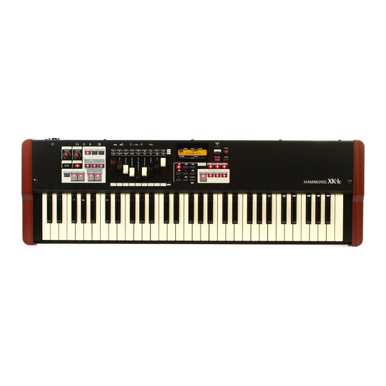
Th ank you, and congratulations on your choice of the Hammond Draw-
bar Keyboard XK-1C.
Please take the time to read this manual completely to take full advantage
of the many features of your XK-1C; and please retain it for future refer-
ence.
MENU /
EXIT
VALUE
RECORD
ENTER
1
2
3
4
5
6
7
8
MANUAL
Advertisement
Table of Contents
Troubleshooting

Related Manuals for Hammond XK-1c


Summary of Contents for Hammond XK-1c
- Page 1 Th ank you, and congratulations on your choice of the Hammond Draw- bar Keyboard XK-1C. Please take the time to read this manual completely to take full advantage of the many features of your XK-1C; and please retain it for future refer- ence. MENU /...
-
Page 2: Important Safety Instructions
Immediately turn the power off , remove the AC adap- adaptor. tor from the outlet, and request servicing by your re- tailer, the nearest Hammond Dealer, or an authorized Do not attempt to repair the unit, or replace parts in Hammond distributor, as listed on the “Service” page it. - Page 3 CAUTION Th e unit and the AC adaptor should be located so Never climb on top of, nor place heavy objects on the their location or position does not interfere with their unit proper ventilation. Never handle the AC adaptor or its plugs with wet Always handle the AC adaptor by the plug when plug- hands when plugging into, or unplugging from, an ging into, or unplugging from an outlet or this unit.
-
Page 4: Important - Please Read
Unfortunately, it may be impossible to restore the contents of data that was stored in another MIDI device (e.g., a se- Placement quencer) once it has been lost. Hammond assumes no li- Using the unit near power amplifi ers (or other equipment ability concerning such loss of data. -
Page 5: Introduction
INTRODUCTION Introduction... -
Page 6: Table Of Contents
Example: RECORD TO U3-2 ................32 Table Of Contents SETTING UP ......33 IMPORTANT SAFETY INSTRUCTIONS ..........2 SOUND ENGINE STRUCTURE .............34 IMPORTANT - PLEASE READ ..............4 ORGAN SECTION ..................35 MASTER EQUALIZER ..................35 INTRODUCTION ......5 ORGAN SECTION ..................36 MAIN FEATURES ..................9 ORGAN TYPE ....................36 TONE-WHEELS (BType1, BType2, Mellow) ..........36 NAMES AND FUNCTIONS ..............10... - Page 7 PARAMETER OPERATION EXAMPLE: ............64 USING A MIDI SOUND MODULE ............ 105 LOCKING THE DISPLAY ................66 ZONES ..................... 106 WHAT IS DISPLAYED ON THE UPPER LEFT? ......... 106 SETTING THE PARAMETERS ...67 INTERNAL ZONE ................... 106 EXTERNAL ZONE ..................106 DRAWBAR ....................68 PANIC FUNCTION AND PARAMETER RE-LOAD ........
- Page 8 CUSTOM TONE-WHEELS LIST ............133 MIDI IMPLEMENTATION CHART ............. 134 MIDI CHANNELS AND MESSAGES ..........135 SPECIFICATIONS .................. 136 SERVICE ....................139 Owner’s Manual...
-
Page 9: Main Features
MAIN FEATURES AUTHENTIC HAMMOND DRAWBAR ORGAN Th e XK-1C is fi rst and foremost a genuine HAMMOND organ with Virtual Tone-Wheels to provide its traditional sound. Also available are the tones of vintage “combo” organs, and a variety of pipe organ ranks to provide church and classical organ voices. -
Page 10: Names And Functions
NAMES AND FUNCTIONS TOP PANEL ❺ VOLUME AMOUNT ❶ ❸ ❼ ❻ ❷ ❹ ❽ ❾ when the light is OFF, it toggles SLOW/FAST(P. 49) UPPER LEFT FAST button ❶ MASTER VOLUME knob Toggles the modes of the rotors FAST or not. When the light Controls the total volume. - Page 11 In the menu mode, this button functions as [ENTER]. (P. 60) KEYBOARD CONTROL P. SUS (Pedal SUStain) button Switches the Pedal Sustain on. (P. 31) M. BASS (Manual BASS) button Switches the Manual Bass on. (P. 30) SPLIT button Divides the XK-1C keyboard into UPPER and LOWER. (P. 30) Introduction...
-
Page 12: Rear Panel
NAMES AND FUNCTIONS - continued REAR PANEL FLASH DRIVE POWER MIDI TERMINALS DC IN jack MIDI OUT jack Connect the AC adaptor AD3-1250 to this jack. MIDI data is output from this jack. (P. 100) MIDI IN jack POWER switch MIDI data received here. -
Page 13: Keyboard
KEYBOARD MENU / EXIT VALUE VOLUME AMOUNT RECORD ENTER MANUAL Keyboard 61 waterfall keys, velocity sensitive. ACCESSORIES AC adaptor Supplies power to the instrument - USE ONLY AD3-1250, DO NOT SUBSTITUTE! AC cord set Attaches AC adapter to Wall outlet. Introduction... - Page 14 14 NAMES AND FUNCTIONS - continued Owner’s Manual...
-
Page 15: Hook-Up
HOOK-UP... -
Page 16: Basic Hook-Up
BASIC HOOK-UP Attach cables and accessories as illustrated. Th ere is no on-board amplifi cation or speaker system. An external amp/speaker is required. When the stereo headphones are connected to the PHONES jack, you can enjoy playing it or practising by yourself. Switch this keyboard, and any external equipment OFF before connecting amps or headphones. -
Page 17: Connecting The Leslie Speaker
(P. 109) direct organ sounds. When this unit detects that the Leslie speaker is connected, the Leslie parameters sent through MIDI from this unit are switched from the XK-1C original to those for the Leslie speaker. Hook-Up... -
Page 18: Expand The Keyboard
“3KBD” or “Two Manual”. the power source, audio, etc. 2. Turn the XK-1C power ON. Th en recall the MIDI template “3KBD”. (P. 108) 3. Set the Send channel of the added MIDI keyboard at “2” and that of the MIDI pedalboard at “3”. -
Page 19: Dual Keyboard
DUAL KEYBOARD FLASH DRIVE MIDI Keyboard MIDI OUT 1. Connect as illustrated. NOTE: This illustration shows only the keyboard expansion. See P. 16 for the basic hook up of the power source, audio, etc. 2. Switch ON the power of this unit. Th en recall the MIDI template “Two Manual”. (P. 108) Refer to the operation manual of the added MIDI keyboard as required. -
Page 20: Using Cu-1 Leslie Switch
EXPAND THE KEYBOARD - continued USING CU-1 LESLIE SWITCH MOUNTING THE CU-1 (optional) 1. Connect the CU-1 to the FOOT SWITCH jack. NOTE: This illustration shows only the keyboard expansion. See P.16 for the basic hook up of the power source, audio, etc. -
Page 21: Getting Ready To Play
GETTING READY TO PLAY... -
Page 22: Switch On
SWITCH ON HOW TO POWER ON After making the necessary connections, follow the procedures below for powering on your XK-1C. Please be sure to adhere to the procedure, to prevent malfunction or dam- age. VOLUME AMOUNT PROCEDURES 1. Before switching the power ON, set the [MASTER VOLUME] knob to minimum. -
Page 23: Play With The Patches
PLAY WITH THE PATCHES Th ere are 64 patches loaded in memory from the factory, allowing you to immediately start playing. You can also create 64 patches of your own. USER and PRESET Patches Th ere are two domains: “USER” and “PRESET” in this key- board’s Patch memory. -
Page 24: Register Favorite Patches (Favorites)
REGISTER FAVORITE PATCHES ( FAVORITES) Patches are selected with the [VALUE] knob. On stage, it is convenient to have your favorite patches avail- able immediately. Here’s how: REGISTER PATCHES TO FAVORITES MENU / EXIT VALUE ENTER RECORD Press and hold Press MANUAL 1. -
Page 25: Locking Patches 1-8
LOCKING PATCHES 1-8 As an alternative to the associated Favorites, You can lock patches 1 through 8, and press a favorite button while holding the [RECORD] button to record the patch - by follow- ing this procedure; LOCATE THE MENU MODE GO TO THE FAVORITE PAGE MENU / MENU /... -
Page 26: Use The Foot Controllers
EXPRESSION PEDAL Th e Expression Pedal controls the overall volume or loudness of the XK-1C. Th e further you depress the pedal, the louder the sound becomes; the more you pull back on the pedal, the softer it. NOTE: The Expression pedal has specifi c parameters to adjust. (P. 26) -
Page 27: Try Creating Your Own Sound
RECORD ENTER MANUAL Press the [PLAY] button. Th is returns the XK-1C to the Play mode. ] button 4 times reaching Page D. Th e ZONE en- Press the [ try is blinking. Press the [ ] button twice. Th e DEFAULT entry is blinking. -
Page 28: Select The Upper Drawbars
NOTE: The present registration is displayed in the Play mode. (P. 59) ADD THE TOUCH-RESPONSE PERCUSSION Hammond’s Touch-Response Percussion adds a distinctive at- tack to the Tone Wheel/Drawbar sounds. Th is percussion is not like a Drum or Cymbal, but closer to an xylophone or ma- rimba. -
Page 29: Add Effects To The Organ Section
ADD EFFECTS TO THE ORGAN SECTION VIBRATO & CHORUS Adding the Classic Hammond Vibrato & Chorus to the sound. [UPPER], [LOWER] buttons Switches the Vibrato & Chorus eff ect ON/OFF. When ON, the light illuminates. [V1/C2], [V2/C2] buttons Th ese set the depth of the Vibrato eff ect. When both buttons are selected, the depth becomes maximum as V3/C3. -
Page 30: What Is A "Part
LOWER PEDAL KEYBOARD SPLIT Th e XK-1C has only 1 manual, but it can be split and will respond as if it were a 2 manual instrument. [SPLIT] button To use the Split function, press the [SPLIT] button and the light will go ON. -
Page 31: Pedal Sustain
PEDAL SUSTAIN A popular eff ect for organ bass is “PEDAL SUSTAIN”, which adds a smooth decay reminiscent of a string bass. [PEDAL SUSTAIN] To engage the pedal sustain, press the [P. SUS] button and the light will go ON. When you release your foot from the pedalboard (or release the key on the keyboard - when using manual bass), the PEDAL part decays smoothly. -
Page 32: Record The Patch To Memory
32 TRY CREATING YOUR OWN SOUND - continued RECORD THE PATCH TO MEMORY All the previous settings can be recorded to any Patch within the range of U1-1 to U8-8. Example: RECORD TO U3-2 MENU / EXIT VALUE Press the [RECORD] button. A question “Which patch do you want to record?”... -
Page 33: Setting Up
SETTING UP... -
Page 34: Sound Engine Structure
SOUND ENGINE STRUCTURE Lower&Upper Pedal Virtual Virtual Tonewheel Set Tonewheel Set Upper Keyboard Pedalboard Lower Keyboard Percussion Pedal Lower Upper Drawbars Drawbars Drawbars Vibrato & Chorus Overdrive Exp. Leslie on Reverb Master Leslie Reverb Multi Effect TC & Equalizer Expression Equalizer Simulator Line Out... -
Page 35: Organ Section
ORGAN SECTION TONE-WHEELS Th e sound source or “engine” of the classic Hammond Organ are the electro-magnetic TONE-WHEEL SETS Tone-Wheel Generators. On this keyboard, the Tone Wheel engine is replicated digitally. The Tone-Wheel Sets are divided into the While the power is on, each of the 96 virtual Tone-Wheels keeps oscillating as they did Manuals and the Pedal Part. -
Page 36: Organ Section
Th is keyboard will sound like the types of organ you choose. TONE-WHEELS (BType1, BType2, Mellow) Th ese are various types of Hammond Organs’ characteristic tone wheels. Th e Ham- mond Organ’s original purpose was to duplicate the pipe organ, however, they be- came famous for producing a unique sound of their own. -
Page 37: Column: Selecting The Organ Types
Column: SELECTING THE ORGAN TYPES Use the control panel for switching the organ types. Example: Switching the manual part to “Pipe” VOLUME AMOUNT Press the [UPPER] and [LOWER] buttons together. Th e DRAWBAR function mode is displayed and the organ type (“BType1”... -
Page 38: Harmonic Drawbars
HARMONIC DRAWBARS™ Th e 9 Drawbars on this keyboard are used to create the basic “Hammond” sounds. Each Drawbar is marked with the register numbers 1 - 8 along the fl at part of the Drawbar. When the Drawbars are fully pushed in, no sound is heard; as the Drawbars are “pulled”... -
Page 39: Drawbars For The Upper And Lower Parts
DRAWBARS FOR THE UPPER AND LOWER PARTS WHITE DRAWBARS In each Drawbar set, the white Drawbar on the left side (8´) provides the fundamental sound. Th e remaining white Draw- bars sound higher by the octave as you move to the right. BLACK DRAWBARS Th e sounds of the black Drawbars play an important role in building rich tones. -
Page 40: Drawbar Registration Patterns
HARMONIC DRAWBARS™ - continued DRAWBAR REGISTRATION PATTERNS Th e Drawbar Registration is matched by digits. It is easy to remember the typical combinations of the 9 Drawbars by their forms. Th e Drawbar Registrations are grouped into the following 4 patterns: Flute family (2 step pattern) Diapason family (check mark pattern) Accompaniment Flute 8´... -
Page 41: Modern Drawbar Registrations
Th e Drawbar registrations introduced on the previous page are typically for classical mu- sic. Th ey were created at the dawn of the Hammond Organ, when it was intended to sound like a pipe or church organ. Later on, as the Hammond Organ spread throughout Jazz, Pop, Rock and (especially) Gospel music, Some timeless registrations become common. -
Page 42: Drawbars (Vx)
4´ 2´ 8´ equipped with Drawbars, but the function was diff erent from that of the Hammond Organ. Th e vintage arrangement has been re-created here. Each of the 4 bars on the left functions sim- ilarly to the Hammond Organ. II, III and IV on the right are “Mixture”... -
Page 43: Drawbars (Farf )
DRAWBARS ( Farf) Th e original Italian Farf type organ was Strings 8´ tablet-equipped with diff erent sounds at Strings 4´ Trumpet 8´ various footages. On this keyboard the op- Strings 16´ Oboe 8´ Piccolo 4´ eration is made with Drawbars instead of Bass 16´... -
Page 44: Drawbars (Pipe)
HARMONIC DRAWBARS™ - continued DRAWBARS ( PIPE) Open Viole Flauto Bourdon Gedeckt Hautbois UPPER: Diapason Celeste Octave Dolce Flute Mixture 16´ 8´ 8´ 8´ 4´ 4´ 2´ Super Trom- Rohr LOWER: Principal Principal Melodia Flute Prestant Flute Octave Mixture pette 16´... -
Page 45: Drawbar Select
DRAWBAR SELECT ASSIGN DRAWBARS TO PARTS Upper Registration Physical Drawbars UPPER PEDAL LOWER Lower Registration Disable Pedal Registration Press Th is keyboard has 3 parts; UPPER, LOWER and PEDAL. Th e Th e Drawbars select buttons are [UPPER], [PEDAL] and UPPER part is normally used, and, when you want to sound [LOWER]. -
Page 46: Percussion
NOTE: You can fi ne-tune the parameters of the Percussion (P. 76). 1´ DRAWBAR CANCEL As on the Vintage Hammond B-3, the 1´ Tone-Wheel Drawbar is inoperative when the Percussion is engaged. NOTE: If you wish the 1´ Drawbar to remain operative, you can change the parameter. (P. 76) -
Page 47: Vibrato & Chorus
VIBRATO & CHORUS Th e Hammond Vibrato & Chorus is another hallmark of the Classic Hammond sound. Vibrato alters the pitch slightly, as a violinist, singer, or guitarist might do. Chorus combines a slightly detuned signal with the original for a lush tone. -
Page 48: Overdrive
OVERDRIVE Overdrive simulates the eff ect of pushing an amplifi er beyond its normal limits to achieve a more aggressive sound. By changing the drive amount, various sounds are obtained from an unclipped warmth to a hard distortion. AMOUNT [OVERDRIVE AMOUNT] knob Adjusts the amount of the Overdrive eff... -
Page 49: Leslie
LESLIE Th e rotating sound of the LESLIE Speaker is the natural partner of the Ham- mond Organ. A Digital version is built-in to the XK-1C; and the controls will also function with a connected external Leslie speaker. [ FAST] button Toggles the mode of the rotor by two steps. -
Page 50: Reverb, Multi-Effects
To engage the Reverb, press this button and the light will go ON. NOTE: You can fi ne-tune the depth, time etc. of the Reverb. (P.95) MULTI-EFFECTS Th e XK-1C has various multi-eff ects such as Tremolo, Wah-Wah and so on. See the “OD/EFF” paragraph (P. 86) for detail. Owner’s Manual... -
Page 51: Manual Bass, Pedal Sustain
MANUAL BASS, PEDAL SUSTAIN Th e PEDAL part may be played on the low part of the keyboard using the MANUAL BASS function. A popular option for playing the Pedals or Manual Bass is Pedal Sustain, which allows the Pedal voice to smoothly decay upon release, much in the manner of a string bass. [M. -
Page 52: Keyboard Split, Octave Shift, Transpose
KEYBOARD SPLIT, OCTAVE SHIFT, TRANSPOSE Th e XK-1C normal range is the UPPER Keyboard. A split is optional to place the LOWER keyboard voices on the left side of the single keyboard. Th e keyboard can be shifted up or down one octave to facilitate easier play. -
Page 53: Patch
PATCH Th e settings (including registrations) you have prepared can be recorded to User Patches. USER AND PRESET Patches Th ere are 64 USER and 64 PRESET Patch- es as illustrated. Th e “User” Patch are over- “VALUE” “FAVORITE” U1-1 First write capable. -
Page 54: Name The Present Setting
PATCH - continued NAME THE PRESENT SETTING GO TO THE MENU MODE GO TO PATCH FUNCTION MODE MENU / MENU / EXIT EXIT VALUE VALUE RECORD ENTER RECORD ENTER Press the [MENU/EXIT] button. Menu mode will be displayed. Press [ENTER] and go to PATCH function mode. GO TO PAGE A MENU / INPUT NAME... -
Page 55: Record To The Patch
RECORD TO THE PATCH Example: RECORD TO “U3-2” GIVE THE NAME Enter the name of your Patch. (P. 54) PRESS THE [RECORD] BUTTON MENU / EXIT VALUE RECORD ENTER Press the [RECORD] button. Th e Record mode is displayed. SELECT THE PATCH NUMBER MENU / EXIT VALUE... - Page 56 Owner’s Manual...
-
Page 57: Using The Control Panel
USING THE CONTROL PANEL... -
Page 58: What You Can Do On The Control Panel
WHAT YOU CAN DO ON THE CONTROL PANEL Your access to deep-editing the XK-1C. All of the parameters and all of the controls not cov- ered by the top panel knobs and switches are here. MENU / EXIT VALUE RECORD... -
Page 59: Play Mode
PLAY MODE Th e Play mode is basic for all operations. All information necessary for ordinary performance is displayed here. To locate this mode 1. “Play mode” is the default mode at power-up. 2. If the Play mode is not displayed, touch the [PLAY] button. HOW TO READ THE DISPLAY Drawbar Registration UPPER / PEDAL / LOWER... -
Page 60: Menu Mode
MENU MODE Th e menu mode provides a directory of all the various functions. To locate this mode: Press the [MENU/EXIT] button. Th ere are many pages functions available to edit. A menu page has up to four items. Search for the item you wish to edit using the direction buttons, then press the [ENTER] button and enter each Function mode. -
Page 61: Menu And The Contents
MENU AND THE CONTENTS PAGE A 1. DRAWBAR Sets the parameters for the Drawbars of each part. (P. 68) 2. TUNE Set the tuning and transpose of the entire keyboard. (P. 71) 3. PATCH Patch naming, Parameter Load and Assignment of Favorites. (P. 70) 4. -
Page 62: Function Mode
FUNCTION MODE Th ese modes are for selecting and controlling the function. All modes can be navigated the same way. HOW TO READ THE DISPLAY There is another page above (or below) this page. PARAMETER (ITEM) NAME Shows there is another page on the right (or the left) of this page. -
Page 63: Short Cut To Function Mode
SHORT CUT TO FUNCTION MODE Each button on the top panel has a built in shortcut-making programming and edit- ing easier. Pressing and holding any of the buttons on the top panel automatically jumps the display to the related function menu item. EXAMPLE OF OPERATION: LOCATE THE PERCUSSION FUNCTION MODE If you wish to edit the percussion settings, press and hold ei-... -
Page 64: Parameter Operation Example
PARAMETER OPERATION EXAMPLE: ADJUST THE [FAST] PERCUSSION DECAY TIME PRESS [ENTER] LOCATE THE MENU MODE MENU / MENU / EXIT EXIT VALUE VALUE RECORD ENTER RECORD ENTER Press the [MENU/EXIT] button. Th e MENU mode is displayed. MANUAL SELECT THE MENU PAGE MENU / EXIT Press the [ENTER] button. - Page 65 RETURN TO THE PLAY MODE MENU / EXIT VALUE RECORD ENTER Press the [PLAY] button. Th e display returns to the PLAY mode. RECORD TO THE PATCH IF DESIRED Th e parameter “DECAY FAST” is a patch parameter, so, when you call a patch, it is changed to the newly set value.
-
Page 66: Locking The Display
LOCKING THE DISPLAY You can lock the display to avoid mistake while playing. MENU / To lock the display, switch [POWER] on with pressing [RE- EXIT CORD] and [MANUAL] until “Display LOCKED” is dis- VALUE played. To unlock this, repeat the operation above until “Display UNLOCKED”... -
Page 67: Setting The Parameters
SETTING THE PARAMETERS... -
Page 68: Drawbar
DRAWBAR Drawbar sound parameters for each keyboard are set in this mode. To locate this mode: See the “Function mode” (P. 62) for operational details. ❶ ❷ ❸ ❹ ❺ ❻ ❼ ❽ ❾ SETTING FOR MANUAL (LOWER & UPPER) DRAWBARS TONE-WHEEL SET There are variations available for each virtual Tone- ❶... -
Page 69: Setting The Pedal Part
LOWER ZONE - OCTAVE Set the octave shift for the LOWER part. Th e setting range is -2 to +2. LOWER ZONE - LOW LOWER ZONE - HIGH Set the sounding range of the LOWER part with these two parameters. See page 102 for details of #7 to 12. -
Page 70: Patch
PATCH In this mode you a name your patch, set which parameters load, and how to link to the Favorite buttons. To locate this mode: See the “Function mode” (P. 62) for operational details. ~ omitted ~ ❸ ❹ ❺ ❻... -
Page 71: Tune
TUNE In this mode, the entire keyboard is tuned. To locate this mode: See “Function mode” (P. 62) for operation details. ❶ ❷ TRANSPOSE ❶ TRANSPOSE You can set Transpose in the range from -6 to +6 semi-tones. Transpose is mapped to the following points: i) Between the built-in keyboard and the on-board sound engines. -
Page 72: Control
FAVORITE FWD, REV: SPRING REVERB Advance the Favorite Forward or Reverse it. SPRING: The Hammond Organ company actually invented This generates the sound of the spring reverb being shaken. the spring reverb for its organs in the 1940’s. The DELAY TIME: eff ect was obtained with a length of spring and a Sets the delay time (P. -
Page 73: Expression
PED (NORM): Using expression limit, you can hear the re- For the (Optional) Hammond-Suzuki EXP-50 or EXP-20 pedal etc. vised frequency response. PED (REV): Vintage B-3 preamps age in diff erent ways-one For using a Korg XVP-10 type of Expression Pedal etc. -
Page 74: Damper
CONTROL - continued ❹ ❺ ❻ ❼ ❽ ❾ ❶ ❷ ❸ DAMPER DAMPER - UPPER (G) DAMPER - LOWER (G) DAMPER - PEDAL (G) DAMPER Assigns the DAMPER to the various divisions of the this keyboard. Or “Sustain” pedal-analogous to the RIGHT pedal DISPLAY on a piano. - Page 75 Setting the Parameters...
-
Page 76: Percuss (Percussion)
PERCUSS ( Percussion) Th is mode is for setting the parameters of the percussion sounds. To locate this mode: or, keep pressing either of the [ON], [THIRD], [FAST], [SOFT] buttons for a moment. See “Function mode” (P. 62) for operation details. ❽... -
Page 77: Vib&Cho (Vibrato & Chorus)
❶ RATE CHORUS EFFECT Sets the Speed of the Vibrato and Chorus eff ect. The Hammond Chorus/Vibrato is not an eve- ryday DSP eff ect. It is a re-creation of the vin- Th e setting range is 6.10 - 7.25 Hz. -
Page 78: Leslie
Th is is for setting the virtual Speaker. RotSmall: A small Leslie speaker, such as the Leslie 145 RotLarge: A large Leslie speaker, such as the Leslie 122 Station: A fi xed speaker, such as the Hammond PR-40 Owner’s Manual... - Page 79 ❺ COLORATION(L) Mode: SLOW FAST SLOW FAST STOP Switches On/Off the coloration of the speaker enclosure. ❻ SLOW SPEED - HORN (L) SLOW SPEED - BASS (L) Sets the speed of the rotor at slow mode. Th e setting range is 0, 24 to 318 rpm. At 0, no rotation. Rotor Speed: ❼...
-
Page 80: External Leslie Speaker
LESLIE - continued EXTERNAL LESLIE SPEAKER LESLIE CHANNELS Sets the channel for the Leslie speaker connected to the LESLIE 8-PIN jack. 1ch: For connecting a 1 channel Leslie cabinet such as the 122XB, 3300/3300W (with no sta- tionary speakers). The Drawbar and the percussion sounds are output only from the rotary channel always. -
Page 81: Cust. Tw (Custom Tone-Wheels)
CUST. TW ( Custom Tone-Wheels) In this mode, you select or edit the characteristics of each tone wheel set to be used on the manual keyboards. To locate this mode: See “Function mode” (P. 62) for operation details. ❹ ❺ ❻... - Page 82 If you decrease the value, a motor hum (= noise) is heard besides the original virtual current tonewheel in play. This “hash” noise, an- Tonewheel sound. other Hammond anomaly originally considered to be a defect grew to be an integral part of the Ham- Th e setting range is 0 - 127.
-
Page 83: Record The Custom Virtual Tonewheels Setting
Record the CUSTOM virtual TONEWHEELS setting Th e Tonewheel Parameters (= 3 - 8 of the previous paragraph) are for determining the Cus- tom Number for recording. Th e Custom Number is selected and used, when you play. Enter the Custom Name if desired. MENU / EXIT VALUE... -
Page 84: Pipe
PIPE In this mode, you edit the characteristics of each pipe. To locate this mode: See “Function mode” (P. 62) for operation details..omitted ... ❶ ❷ ❸ ❹ ❺ ❻ ❼ ❶ PIPE NUMBER Select the PIPE which you desire to edit by [ ],[ ] buttons. Th ere are 20 pipes which according to Drawbars from “Bourdon 16´”... - Page 85 ❼ PAN - IMAGING (Pi) Sets the arrangement of the pipe. FIX: Sounds the FIXed direction which set by #6 for all notes. L-R: Sounds Left to Right which according to the keys. C MISSING OR UNEVEN VOICE? E The pipe stops are spread in a stereo array.
-
Page 86: Od / Eff (Overdrive / Effects)
OD / EFF ( Overdrive / Eff ects) In this mode, Overdrive and the Multi-Eff ects are adjusted. To locate this mode: Or, turn the [OVERDRIVE AMOUNT] knob with pressing [MENU/EXIT] button. See “Function mode” (P. 62) for operation details. ❺... - Page 87 Tremolo Tremolo modulates the volume at a set cycle. Level Depth ❻ ❼ ❽ ❾ ❼ TREMOLO - WAVEFORM Sets which waveform is used to modulate the volume. Tri: Triangle wave. The volume changes smoothly. Sqr: Square wave. The volume suddenly rises and falls. Saw: Sawtooth wave.
- Page 88 OD / EFF (Overdrive / Eff ects) - continued Wah-Wah Wah-Wah imposes a “speech-like” dynamic to the sound. ❻ ❼ ❽ ❾ ❼ Wah-Wah - SOURCE Selects the source of the WAH control. Waveform, EXP: Uses the Expression Pedal like a “Wah Wah pedal”. Rate LFO: Auto-Wah using the built-in ‘LFO - Low Frequency Oscillator’...
- Page 89 Ring Mod. Th e Ring Modulator creates complex, metallic-like sounds by taking the sum and diff er- ence of the fundamental tone and a second “ring” frequency. ❻ ❼ ❽ ❾ ❼ RING MODULATOR - SOURCE Waveform, Selects what to use to modulate the ring frequency. Rate EXP: Modulates the ring frequency with the Expression Pedal.
- Page 90 90 OD / EFF (Overdrive / Eff ects) - continued Phaser Th is eff ect adds a twisting character to the sound by shifting phase. ❻ ❼ ❽ ❾ ❼ PHASER - RATE Adjusts the frequency speed. Th e setting range is 0 to 127. Th e cycle becomes faster as the value increases. Rate ❽...
- Page 91 Flanger Th is eff ect adds the sweeping “Jet Airplane” characteristic, adjustable from a mild shim- mer to a deep “swoosh”. ❻ ❼ ❽ ❾ ❼ FLANGER - RATE Adjusts the modulation speed. Rate Th e setting range is 0 to 127. Th e cycle becomes faster as the value increases. ❽...
- Page 92 Chorus Th is “Chorus” is NOT the same as Hammond’s proprietary “Chorus-Vibrato”. Th is eff ect is the familiar Chorus as heard widely on electric pianos, guitars, etc. ❻ ❼ ❽ ❾ ❼ CHORUS - RATE Adjusts the speed of the cycle of the rising and falling eff ect pitch.
- Page 93 Delay Th is is for adding echo eff ects. ❻ ❼ ❽ ❾ ❼ DELAY - TYPE Level TYPE = MONO Select the type of delay here. Original Signal MONO: Effect Signal A simply monophonic “echo”. RtoL, LtoR: The delay is alternated in the stereo fi eld. At RtoL the delayed sound comes from the right, and at LtoR from the left.
-
Page 94: Equaliz (Equalizer)
In this mode, you adjust the settings for the Equalizer. An Equalizer is used to adjust the tonal quality. Th e XK-1C’s built-in Equalizer con- sists of 3 bands and a recreation of the unique “tone” control that was part of the vintage B-3. -
Page 95: Reverb
REVERB In this mode, you set the Reverb eff ect. To locate this mode: or, keep pressing the [REVERB ON] button for a few seconds. See “Function mode” (P. 62) for operation details. ❻ ❸ ❹ ❺ ❶ ❷ ❶ DEPTH Th is sets the depth (volume) of the Reverb Eff... -
Page 96: Default
DEFAULT In this mode, you can go back totally or partially to the factory default settings. To locate this mode: ❺ ❻ ❼ ❶ ❷ ❸ ❹ To initialize each parameter, select the parameter you want to initialize with the [ ][ ] button and press the [ENTER] button. -
Page 97: System
SYSTEM In this mode,the audio output mode and the System information of the XK-1C is displayed. To locate this mode: See “Function mode” (P. 62) for operation details. ❻ ❼ ❽ ❷ ❸ ❹ ❺ ❶ ❶ AUDIO MODE - OUTPUT Sets the audio mode of output jacks. - Page 98 Owner’s Manual...
-
Page 99: Midi
MIDI... -
Page 100: About Midi
ABOUT MIDI WHAT IS “MIDI”? MIDI is an acronym of ‘Musical Instrument Digital Interface’. MIDI is the musical instrument industry standard for exchanging performance infor- mation between electronic musical instruments and a sequencer, eff ects, lighting, and sound reinforcement gear, etc. Th e MIDI standard allows instruments made by diff... -
Page 101: Main Midi Message
MIDI CHANNEL MIDI has 16 “Channels”. All channels transmitted through one MIDI cable. Th e channel must match between the sender and the receiver. If not, the machines can not “hear” what the other “says”. MAIN MIDI MESSAGE Th e MIDI information is grouped into a channel message per each of the 16 channels and a system message for all channels. -
Page 102: Midi Structure
MIDI STRUCTURE Th is keyboard has “Keyboard Channels” to transmit playing information of the key- boards and “External Zone Channels” to control external MIDI equipment on the keyboards. Map of the MIDI structure Organ Section Octave Shift (part) Octave Shift (int. zone) Key Range Split Point Upper... - Page 103 Map of the MIDI structure Organ Section Octave Shift (part) Octave Shift (int. zone) Keyboard Extended Key Range Upper Upper Kbd. ExZone 1 Upper Keyboard Lower Lower Kbd. Manual Bass Pedal Kbd. ExZone 2 Octave Shift (ext. zone) Lower Keyboard On/Off &...
-
Page 104: Using An External Sequencer
2. Call the others than the “Use Ex.” (“Basic”, “Two Manual”, “Pedal KBD”, or “3KBD” depending on your hooked up) of MIDI template (P. 108) Th is hookup is only for recording/playing the XK-1C by itself, not External Zones.*1. 3. Set the MIDI channel of the Sequencer/DAW. -
Page 105: Using A Midi Sound Module
USING A MIDI SOUND MODULE You can control an external MIDI sound module with the built-in keyboard and the expanded MIDI keyboard. MIDI Keyboard MIDI OUT Optional MIDI Pedalboard (MERGE) MIDI IN MIDI Sound Module 1. Connect as illustrated. WHY USING EXTERNAL ZONES Connect the MIDI OUT of this keyboard to the MIDI IN of the MIDI sound module. -
Page 106: Zones
Sets which keyboard to allocate this zone. On the upper left of the Zone mode, the Zone to be operated now is displayed. Set to the UPPER if it is only the XK-1C. INT: Internal zone If there is an expanded keyboard, you can control the external XZn: External zone (#n) zone using the Lower keyboard or the Pedalboard. -
Page 107: Panic Function And Parameter Re-Load
Sets the range to “compress” the expression information to send to this zone. In the XK-1C default, if the expression pedal is pulled fully back, the output does not perfectly silent. If a GM sound gen- erator is used, the volume would go to zero. Th is is a parameter to balance the two. -
Page 108: Midi
MIDI In this mode, you make the basic MIDI settings and the memory To locate this mode: dump operation. See “Function mode” (P. 62) for operation details. ❷ ❸ ❹ ❺ ❻ ❼ ❽ ❾ ❶ engine are connected. When OFF, the keyboard(s) and the MIDI TEMPLATE sound engine are disconnected no sound is played. -
Page 109: Keyboard Channels
is neglected, when the Device ID does not match, even if the RX LOWER messages for the same model. Sets the MIDI channel for receiving the LOWER part playing information. RECEIVE DUMP Th is switches reception of Memory Dump ON/OFF. RX PEDAL Sets the MIDI channel for receiving the PEDAL part playing On this keyboard the total onboard memory can be transmit-... - Page 110 Owner’s Manual...
-
Page 111: Save The Setup
SAVE THE SETUP... -
Page 112: Save Your Setup
The patch fi les are saved here. The extension “PAT” is automatically given to the NOTE: If your USB drive is formatted so the XK-1C cannot read it, the XK-1C will initialize patch fi le treated on this keyboard. your drive automatically. Do NOT use this USB drive for anything else than your XK-... -
Page 113: Initialize The Usb Flash Drive
INITIALIZE THE USB FLASH DRIVE A “fresh” Th e USB fl ash drive must be “initialized”. Th e initializing procedure is as follows: When initializing is completed, all the contents of the USB fl ash drive are erased. MENU / EXIT FLASH DRIVE VALUE... -
Page 114: Setup Procedures
SETUP PROCEDURES Save or Load the SET-UPS to/from the USB fl ash drive in the SETUP mode. To locate this mode: MENU/ EXIT ENTER HOW TO READ THE DISPLAY SETUP name This indicates there is another Type of File SETUP fi le above (or below). SU: SetUp This indicates there is another What your are going to operate... -
Page 115: Change The Setup Name
CHANGE THE SETUP NAME MENU / EXIT VALUE RECORD ENTER Select the setup fi le you want to change the name of with the [ ],[ ] buttons or the [VALUE] knob. MANUAL Enter the new setup name. MENU / EXIT [ ],[ ] buttons VALUE... -
Page 116: Load The Setup
LOAD THE SETUP DELETE THE SETUP If you do this operation, the settings in this keyboard are replaced with the newly loaded setups. You should save important data beforehand (p. 114). Check the USB fl ash drive is correctly inserted. Check the USB fl... -
Page 117: Patch Procedures
Th ere is a fi le with same name already. Change the patch name above, “To locate this mode”. on the XK-1C, or delete the fi le with same name in the USB fl ash drive (next page). WHAT DOES THIS MEAN? USB is not ready. -
Page 118: Load The Patch File
LOAD THE PATCH FILE DELETE THE PATCH FILE If you do this operation, a patch in this keyboard are replaced with the newly loaded patch. You should save important data beforehand (p. 117). Check the USB fl ash drive is correctly inserted. Check the USB fl... -
Page 119: Troubleshooting
Troubleshooting... -
Page 120: Troubleshooting
TROUBLESHOOTING Malfunction of the buttons, the keys, etc. Turn off the POWER switch once, then turn it on again. If this procedure is not suc- cessful, turn off the POWER switch. While pressing the [RECORD] button, turn the POWER switch on again. (Note that in this case, all parameters all parameters return to their factory-preset status.) No sound is produced when the keys are pressed. -
Page 121: Appendix
APPENDIX... -
Page 122: Midi Templates
MIDI TEMPLATES MIDI TEMPLATES Template Basic Two Manual Pedal KBD Sequence Lower Pedal Messages MIDI IN Local Control NRPN Program Change Drawbar Registration Transmit Channel Tx. Upper Tx. Lower Tx. Pedal Rx. Upper 1 (disregarded, off ) 1 (disregarded, off ) Rx. -
Page 123: Preset Patch List
PRESET PATCH LIST Category Name Category Name Vintage B-3 Classic Gospel P1-1 P6-1 P1-2 Purple Smoke P6-2 Slow Gospel SQUABBLE Contemp.Gospel P1-3 P6-3 P1-4 Open Th e Doors P6-4 Shout Gospel ChurchPipeOrgan Quiet Praise P1-5 P6-5 P1-6 Drawbars Dimed P6-6 Refl... -
Page 124: Midi Information
MIDI INFORMATION NRPN MSB/LSB (CC#98, 99) MIDI Implementation Status 2nd Byte 3rd Byte Channel Voice Message n=MIDI Channel Number: 0H - FH (Ch. 1 - 16) Note Off mm=upper byte of the parameter number specified by NRPN Status 2nd Byte 3rd Byte ll=lower byte of the parameter number specified by NRPN vvH, or n=MIDI Channel Number:... -
Page 125: Drawbar Data List 1
Drawbar Data List 1 Control Number Upper: 50H(80) Lower: 51H(81) Pedal: 52H(82) Upper / Lower Pedal Level 16´ 5 1⁄3´ 8´ 4´ 2 2⁄3´ 2´ 1 3⁄5´ 1 1⁄3´ 1´ 16´ 8´ 00H(0) 09H(9) 12H(18) 1BH(27) 24H(36) 2DH(45) 36H(54) 3FH(63) 48H(72) 00H(0) 09H(9) 01H(1) -
Page 126: System Exclusive Message
MIDI INFORMATION - continued System Exclusive Message Memory Dump Mode Setting Exclusive Message 1. Each Packet Full Parameters Reset (Rx. only) System Exclusive System Exclusive SUZUKI ID SUZUKI ID Device ID (refer to P. 108 #9) Device ID Model ID MSB Mode ID for DT1 Model ID LSB Command: DT1... -
Page 127: Global Parameters
Global Parameters Category Parameter NRPN SysEx Address SysEx Data Default Description MSB to LSB Length (62) (63) Tune Transpose 3A - 40 - 46 (-6 - 0 - 6) Master Tune 032E - 0338 - 0342 0338 (430 - 440 - 450) Expression Source 00 - 01... -
Page 128: Patch Parameters
MIDI INFORMATION - continued Patch Parameters Category Parameter NRPN SysEx Address SysEx Data Patch Load MSB to LSB Length (62) (63) Name 15 Characters 7 bit ASCII always Internal Zone Manual Bass 00, 01 (Off /On) Manual Bass Mode 00 - 02 (Lower, Chord, Poly) Manual Bass Range Hi 24 - 60 (MIDI note number) Great To Pedal... - Page 129 Category Parameter NRPN SysEx Address SysEx Data Patch Load MSB to LSB Length (62) (63) Percussion Percussion On 00, 01 (Off /On) DRAWB Th ird On 00, 01 (Off /On) Decay Fast 00, 01 (Off /On) Volume Soft 00, 01 (Off /On) Level On Soft 00 - 0F (1 - 16) Level On Normal...
- Page 130 130 MIDI INFORMATION - continued Category Parameter NRPN SysEx Address SysEx Data Preset Load MSB to LSB Length (62) (63) Pedal Tonewheel Set 00 - 03 DRAWB 00: Normal 01: Muted 02: Synth 1 03: Synth 2 Attack 00 - 04 00: Slow Attack 01: No Click 02: Soft Click...
- Page 131 Category Parameter NRPN SysEx Address SysEx Data Preset Load MSB to LSB Length (62) (63) Eff ects Overdrive On 00, 01 (Off /On) EFFECT p=0: DRAWB Overdrive Type 00 - 03 00: Tube 01: Stomp Box 02: Clip 03: E. Pf. Amp Overdrive Drive Level 00 - 7F Overdrive Controlled Exp.
-
Page 132: Leslie Parameters
MIDI INFORMATION - continued Leslie Parameters Category Parameter NRPN (XK) NRPN (21) SysEx Address SysEx Data MSB to LSB Length (62) (63) (62) (63) Name (10 Characters) Cabinet Slow Speed Horn Slow Speed Bass Fast Speed Horn Fast Speed Bass Rise Time Horn Rise Time Bass Fall Time Horn... -
Page 133: Custom Tone-Wheels List
Noisy 60 Type based upon very prominent leakage noise. Mellow Full Flats Type based on perfect sine waves, and a hypothetical Hammond in which all tone wheels oscillate at the same volume. Husky Type with characteristics of mid-range and reduced volume. -
Page 134: Midi Implementation Chart
MIDI IMPLEMENTATION CHART Date: 28-Jun-2013 Drawbar Keyboard MIDI Implementation Chart Model: XK-1C Version: 1.0 Function Transmitted Recognized Remarks Basic Default *1: Upper = 1, Lower = 2, Changed 1 - 16 1 - 16 Pedal = 3 Channel Default Messages... -
Page 135: Midi Channels And Messages
MIDI CHANNELS AND MESSAGES External Zone Upper Lower Pedal (Tx. only) Part Part Part Note Pitch Bend Modulation Volume O *1 (10) Expression (11) O *1 Hold 1 (64) Drawbar Reg. CC#80, CC#81 CC#82 12 - 20 (Upper) 21 - 29 (Lower) 33, 35 (Pedal) Spring Shock, Glide (48, 49) -
Page 136: Specifications
SPECIFICATIONS Sound Generator Controllers Volume 2 - VASE III as Digital Tone-wheels, Transistor Organ and Pipe Organ 61 polyphony (for manual, except Pipe Organ) Master Volume 8 polyphony (for pedal, except Pipe Organ) Switch 63 polyphony (maximum, on Pipe Organ) Power On/Off... - Page 137 Function Mode 62 Index Panic Function 107 Parameter 64 Glide 73 Part 30 Associate 70 Patch 23, 53, 70, 117 Auto Pan 87 patch fi le 117 Harmonic Drawbars 38 Patch Level 70 Patch Load 53, 70 Back Up 22 Pedalboard.
- Page 138 Vibrato & Chorus 29, 47, 77 Vx 36, 42 Wah-Wah 88 Zones 106 Owner’s Manual...
-
Page 139: Service
Although every attempt has been made to insure the accuracy of the descriptive contents of this Manual, total accuracy cannot be guaranteed. Should the owner require further assistance, inquiries should fi rst be made to your Authorized Hammond Dealer. If you still need further assistance, contact Hammond at the following addresses:... - Page 140 Printed in China 00457-40189 V1.00-130806 HAMMOND SUZUKI, LTD., Hamamatsu, Japan...
Need help?
Do you have a question about the XK-1c and is the answer not in the manual?
Questions and answers