
Related Manuals for Hammond XK-3C


Summary of Contents for Hammond XK-3C
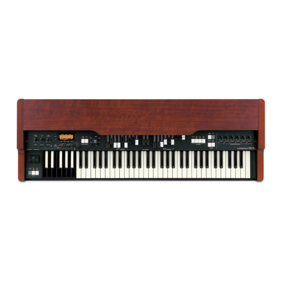
- Page 1 Model Thank you, and congratulations on your choice of a Hammond XK-3C. In order to get the most out of this instrument for many years to come, first take the time to read this manual in full. Owner’s Manual...
-
Page 2: Important Safety Instructions
IMPORTANT SAFETY INSTRUCTIONS Read these instructions. Protect the power cord from being walked on or pinched, particularly at plugs, convenience receptacles, and the point Keep these instructions. where they exit from the apparatus. Heed all warnings. Only use attachments/accessories specified by the manu- facturer. - Page 3 If the fuse cover is lost, the plug must not be used until a replacement cover is obtained. A replacement fuse cover can be obtained from your local Hammond Dealer. IF THE FITTED MOULDED PLUG IS UNSUITABLE FOR THE SOCKET OUTLET IN YOUR HOME, THEN THE FUSE SHOULD BE REMOVED AND THE PLUG CUT OFF AND DISPOSED OF SAFELY.
-
Page 4: Important - Please Read
IMPORTANT - PLEASE READ Your Hammond XK-3C Drawbar Keyboard is designed to give you the true and authentic sound of Hammond Harmonic Drawbars, as well as provide you a large variety of features to allow great flexibility in how you want to use the keyboard. -
Page 5: Battery Back Up
If there is no battery installed in the unit, or if the battery is compeletely dead, the Display will show: After the above message is displayed, the XK-3C will re-initialize itself, and the factory default settings will be restored (except Combination Presets, Leslie Cabinets and Cutsom Tone-Wheels). Therefore, it is a good idea to periodically save your data to CompactFlash card. -
Page 6: Table Of Contents
Table Of Contents SETTING UP ..........29 IMPORTANT SAFETY INSTRUCTIONS ..........2 IMPORTANT - PLEASE READ ............4 SOUND ENGINE STRUCTURE ............30 BATTERY BACK UP ................. 5 SYSTEM STRUCTURE OF THIS KEYBOARD ........30 Index ................... 8 DRAWBARS™ ................32 MANUAL DRAWBARS ................. - Page 7 RECORD THE CABINETS ..............75 System Exclusive Message ............114 VIB&CHO (VIBrato and CHOrus) ..........76 Global Parameters ..............115 VIBRATO AND CHORUS OF HAMMOND ORGANS ......77 Preset Parameters ..............116 OVERDRIV (OVERDRIVe) .............. 78 Tone-wheel Parameters ............. 119 BIAS VOLTAGE AND NONLINEAR DISTORTION ........
-
Page 8: Index
Index Master Tune 67 Menu Mode 50 Adjust Preset 24, 82, 100 Velocity 57, 71 MIDI 86, 96 Assign 60 Vibrato/Chorus 25, 38, 76 Modulation 63 Combination Preset 22, 42 Zones 92 Noise Gate 83 CompactFlash Card 100 Custom Tonewheels 68 Overdrive 25, 39, 78 Default 82 Demonstration 21... -
Page 9: Main Features
DIGITAL LESLIE / VIBRATO EFFECTS. The XK-3C keyboard is equipped with a DSP effect generator to simulate the Scanner-Vibrato and Leslie Speaker. The range of sounds that you can create is expanded by the use of Vibrato and Chorus effects, and by the real sounding Leslie effects which effectively simulates the rotation of the two Rotors which are present in traditional Leslie. -
Page 10: Names And Functions
NAMES AND FUNCTIONS Front Panel 15 16 11. PARAM Button UPPER LEFT Selects Parameters. MASTER VOLUME Knob 12. VALUE Button Controls the total volume. Increases and decreases the value. CONTROL Button 13. VALUE Knob Sets up various controls. Adjusts the value. TONE Knob 14. - Page 11 29 30 31 32 252627 28 DRAWBARS UPPER RIGHT 20. LEFT DRAWBARS 29. REVERB Button Controls UPPER part or B key harmonics. Switches on and off the REVERB Effect. 21. LEFT DRAWBARS LED 30. USER Button Indicates the function of the left drawbars. With this button you can assign the function you want.
-
Page 12: End Block
End Block 37 38 39 WHEEL KEYBOARD 35. PITCH BEND Wheel 40. PRESET Key Slides the pitch up or down. This is used to select the Combination Presets. The pitch goes up when moved up, and goes down when moved The Bank is selected by pressing this key, holding down BANK down. -
Page 13: Rear Panel
Rear Panel 42 43 44 45 46 48 49 LEFT SIDE OF REAR [The factory setting] The MIDI information received by chan- nel. You can set that through this terminal functions as LOWER, 42. AC Inlet regardless of the channel. Connects the A.C. -
Page 14: Effect Loop
54. LINE OUT R If you insert a plug into this jack, it disconnects the internal unit, This is the Right channel output of the XK-3C. and signals are not put out from the output jack, except the sig- Use the Left and Right output Jacks if your mixer or amplifier nal input from RETURN jack. -
Page 15: Hook-Up
HOOK-UP Owner’s Manual... -
Page 16: Basic Hook-Up
BASIC HOOK-UP See the figure below for connection. Amplifiers or speakers are not mounted in this keyboard. You must connect an external amplifiers and speakers (or Powerd Speaker) in order to hear the keyboard sounds. You can also enjoy playing this keyboard by connecting Stereo Headphones to the Head- phone Jack. -
Page 17: Connecting The Leslie Speaker
CONNECTING THE LESLIE SPEAKER This keyboard is equipped with a 11 Pin Leslie Connector, so you can directly connect the Leslie Speaker. Do this connection after switching OFF the keyboard. Connect the Leslie Speaker to the 11 Pin Terminal on the eg. -
Page 18: Connecting The Midi Keyboard
CONNECTING THE MIDI KEYBOARD You can upgrade this keyboard to an organ by connecting an external MIDI Key- board and pedal keyboard. MIDI Keyboard Expression Pedal MIDI Pedal Keyboard EXP-100F 1. Hook-up external MIDI keyboard and pedal keyboard per the figure above. 2. -
Page 19: Turn On And Play
TURN ON AND PLAY Owner’s Manual... -
Page 20: Power On
BACK-UP Your XK-3C memorizes the setting of the keyboard immediately before it is switched off. So, The keyboard will start with these settings when it is switched on again. This is called “Back-up”. The XK-3C is initially shipped from the factory with the Preset Key [B] in “pressed” status. -
Page 21: Listen To The Demonstration Performance
LISTEN TO THE DEMONSTRATION PERFORMANCE In your XK-3C, the demonstration performance is built in for introducing the features and sound. STEPS Touch and hold the [MANUAL BASS] and [SPLIT] Button for 2 seconds. The Display will be as shown in step 2. -
Page 22: Play With The Combination Preset
You can record various settings to the Preset Keys mounted The Preset data is recorded in the Banks C to B at the fac- on the left-hand side of the XK-3C. This is called “Combi- tory. Thus you can start playing immediately. -
Page 23: Play With The Controllers
You will see on this page how to use the controllers generally used with the electronic musical instruments. (How to use the exclusive Hammond Organ controllers is shown on the next page.) PITCH BEND WHEEL This is used to slide the pitch up or down while playing. -
Page 24: Try To Make Your Own Sound
You will be able to freely produce your own sound by using the exclusive features of your HAMMOND ORGAN, such as Drawbars and Percussion sound, as well as Vibrato and the Leslie effects. The steps to take after you receive your XK-3C from your dealer are as follows: SELECT THE PRESET KEY [B] First select the Preset Key [B]. -
Page 25: Add Effects
ADD EFFECTS “Vibrato and Chorus” slightly changes the Drawbar pitch at a certain ratio and add warmth to the VIBRATO & CHORUS sound. [UPPER] Button Switches on and off the Vibrato effect. The LED turns on when it is ON. [VIBRATO &... -
Page 26: Divide The Keyboard Into Two Parts - Left And Right. [Split]
Divide the keyboard into two parts - left and right. [SPLIT] This keyboard has only a single manual. But you can change the setting and play it as it was a double keyboard organ, using this “SPLIT” function. [SPLIT] Button Switch on the LED by pressing the button, to “split”... -
Page 27: Storing Registrations In Combination Preset
STORING REGISTRATIONS IN COMBINATION PRESET All the afore-mentioned settings can be memorized to the Combination Preset. The data stored at the factory can also be freely re-written. EX. Memorize to “F - D”. Light 1. While pressing the [BANK] Button, press the Preset Key [F]. The LED on the Preset Key indicates BANK while the [BANK] Button is pressed. - Page 28 Owner’s Manual...
-
Page 29: Setting Up
SETTING UP Owner’s Manual... -
Page 30: Sound Engine Structure
SOUND ENGINE STRUCTURE SYSTEM STRUCTURE OF THIS KEYBOARD Owner’s Manual... -
Page 31: Tube Amp
TUBE AMP Having a real tube in the Amp gives the XK-3C a unique tube sound. By chang- ing the amount of the drive you can obtain various tube sounds from “clean” no clipping, to the hard-distorted fuzzy and raspy “overdrive”. -
Page 32: Drawbars
DRAWBARS™ The 9 Drawbars (plus 2 for the Pedal) on this keyboard are used to make the basic sounds. Each Drawbar is marked with the numbers 1 - 8. If you push back the Drawbar until you can not see any number at all, the sound of the Drawbar is not heard. If you pull it out to the fullest position THE SOUND LEVEL is maximum. -
Page 33: Manual Drawbars
MANUAL DRAWBARS WHITE DRAWBARS In each Drawbar set, the white Drawbar (8') on the left end makes the basic/ fundamental sound. The other white Drawbars get higher by the octave to the right. BLACK DRAWBARS The sounds of the black Drawbars, too, play important roles in building rich tones. -
Page 34: Drawbar Registration Patterns
DRAWBAR REGISTRATION PATTERNS The Drawbar Registration is matched by digits, if precisely. However, in the usual play, it is rather reasonable to remember the typical combinations of the 9 Drawbars by their forms/shapes. The Drawbar Registrations are roughly grouped into the following 4 patterns: Flute family (2 step pattern) Accompaniment Flute 8' I 00 8460 000... - Page 35 Diapason family (check mark pattern) Accomp. Diapason 8' 00 8874 210 Chorus Diapason 8' 00 8686 310 Diapason 8' 00 7785 321 Echo Diapason 8' 00 4434 210 Harmonic Diapason 16' 85 8524 100 Harmonic Diapason 8' 00 8877 760 Harmonic Diapason 4' 00 0606 045 Horn Diapason 8'...
-
Page 36: Sets Of Drawbars And Parts
3 SETS OF DRAWBARS AND PARTS On this keyboard, there are 3 Parts: UPPER, LOWER and PEDAL, and each of them has the corresponding Drawbars. The manual on the keyboard is usually assigned to the UPPER position. If you want to play the LOWER or PEDAL Part, use the Split or Manual Bass functions, or connect the MIDI keyboard and assign each part. -
Page 37: Percussion
PERCUSSION The attack feeling of the percussion is a Hammond exclusive. Percussion is usually used with the Drawbar sound. [SECOND] BUTTON DECAY The second harmonic, or 4' Drawbar decay, is added to the UPPER Part. To use this, press the [SECOND] button, and the LED will light. -
Page 38: Vibrato & Chorus
VIBRATO & CHORUS VIBRATO adds warmth to the tone, by slightly changing the Drawbar pitch at a certain speed. You can also add richness to the sound by mixing the Vibrato sound with the funda- mental (= Chorus Effect). [UPPER] BUTTON This switches ON and OFF Vibrato and Chorus Effects. -
Page 39: Tube Amp
TUBE AMP The TUBE (= Vacuum Tube) AMP produces a unique “Tube Feeling” sound. By changing the amount of the Drive, various Tube Sound is obtained, from the unclipped clean to the hard-distorted fuzzy, raspy Overdrive sound. [TUBE AMP] BUTTON TUBE AMP CIRCUIT This is for determining whether or not to go through the Tube Amp circuit. -
Page 40: Leslie
LESLIE LESLIE EFFECT is the simulated sound of the rotating speakers. If you connect the real Leslie speakers to this keyboard, it controls those (speakers). [ON] BUTTON If you touch this button, the LED will light, and the rotor starts turning. Also the voice is heard thru the rotary channel. -
Page 41: Equalizer & Reverb
EQUALIZER & REVERB The Equalizer and the Reverb effects give the final touch to the tone. The Equalizer regulates the tone, and the Reverb adds the resonance of the hall perfor- mance. You can control portions of their functions on the panel buttons and knobs EQUALIZER [TONE] KNOB One optional Parameter out of the Equalizer is assigned and regulated. -
Page 42: Combination Presets
[C] to [A]. COMBINATION PRESETS On the original B-3 organ the preset keys only stored drawbar reg- istration information. On the XK-3C however in addition to drawbar registration you can store many various parameters to a preset. Thus the name “Combination Preset”. -
Page 43: Name The Combination Presets
NAME THE COMBINATION PRESETS Go to the MENU. Touch the [MENU/EXIT] button. The MENU mode will be displayed. Go to PAGE A. If the PAGE A is not displayed, touch the [PAGE] button and go to PAGE A. Go to the PRESET FUNCTION mode. Touch the [2] PRESET button and go to the PRESET FUNC- TION mode. -
Page 44: Record Into The Combination Presets
RECORD INTO THE COMBINATION PRESETS EXAMPLE: Record into “F-D”. Select the Bank. While holding down the [BANK] button, touch the Preset Key Light [F]. The LED on the Preset Key indicates the BANK while you are holding down the [BANK] button. Press and hold NOTE: The LED will be OFF, if you release the button. -
Page 45: Locking The Combination Preset
LOCKING THE COMBINATION PRESET You can lock the Combination Preset to avoid calling it out by mistake while playing. To lock the Combination Preset, press both the [BANK] and the [REC/JUMP] buttons for longer than 1 second, after calling out the Ccombination Preset you want to lock. “Preset LOCKED”... - Page 46 Owner’s Manual...
-
Page 47: Using The Control Panel
USING THE CONTROL PANEL Owner’s Manual... -
Page 48: Operation Control Panel
OPERATION CONTROL PANEL You now know you can do many settings by using the buttons and knobs on your keyboard. You can do even finer settings like the delicate speed of the Leslie Effect or the MIDI equipments, using the display buttons on the Con- trol Panel. -
Page 49: Play Mode
PLAY MODE The PLAY MODE is the basic display for all the operations. The necessary informa- tions for the normal play will be displayed. There are two types of PLAY MODE screens to display the Drawbar Registration. One is by showing the length of the bars and the other by digits. To locate this mode: Immediately after powered ON and the start up process is complete, the PLAY mode is displayed. -
Page 50: Menu Mode
MENU MODE The MENU mode is the path for each function. To locate this mode: Touch the [MENU/EXIT] button. There are several pages which contains many various FUNCTION displays. Move from page to page and find the item where you want to go and touch the numbered button to see the desired display. -
Page 51: Function Mode
FUNCTION MODE The FUNCTION MODE is for making each setting and adjustment. There are many displays, but the basic operation is the same. HOW TO READ THE DISPLAY This shows there are PAGEs above (or below). PARAMETER This shows there is a PAGE on the right (or on the left). -
Page 52: Example Of Operation
Example of operation: Adjusting the DECAY TIME of the Percussion [FAST] Go to the MENU Mode. Touch the [MENU/EXIT] button. The [MENU] mode is displayed. Select the PAGE. Search for the PERCUS page, using the [PAGE] button. “PERCUS” is on PAGE B. So select PAGE [B]. Touch the Number button. - Page 53 Move the CURSOR to the Parameter you want to change. DECAY TIME is on the “DECAY” PAGE. Move to that page using the [PAGE] button. “FAST” is on the right end. Move the CURSOR (flashing value) to underneath “FAST” using the [PARAM] button. Change the value.
-
Page 54: Short Cut To The Function Mode
SHORT CUT TO THE FUNCTION MODE Each button on the panel has a “SHORT-CUT” capability, so that you can easily go to each Function mode. By holding down the button, you can easily go to the desired mode display. You can save time to search the page for the parmeters you want to change. -
Page 55: Setting The Parameters
SETTING THE PARAMETERS Owner’s Manual... -
Page 56: Drawbar
DRAWBAR In this mode, you can set the Parameter relating to the Drawbar sound of each part. To locate this mode: Touch the [MENU/EXIT] button and display MENU, touch the [PAGE] button and select PAGE A and choose [1] DRAWBAR. Setting the Manual Part (LOWER and UPPER) TONE-WHEEL SET 1. -
Page 57: Setting The Pedal Part
Setting the PEDAL Part 7. TONE-WHEELS This allows you to select the Tone-wheel set (waveform) of the PEDAL Part. Normal Normal Normal Normal Normal:The traditional B-3/C-3 Tone-wheel sound Muted Muted Muted Muted Muted: Analog-oscillating sound represented by the X-5. Synth1 Synth1 Synth1: Sawtooth waveform with sweep filter. -
Page 58: Preset
PRESET In this mode, you can name your Combination Presets and determine how to recall them. To locate this mode: Touch the [MENU/EXIT] button and display MENU, then touch the [PAGE] button to select PAGE A and touch the [2] PRESET button. PRESET NAME 6. -
Page 59: Effective Use Of Link-Lower/Pedal
EFFECTIVE USE OF LINK-LOWER/PEDAL This is the function to switch/record only from the connected MIDI equipment, and not to operate the Preset for LOWER and PEDAL Part on this keyboard. The Preset Keys on B-3/C-3 are independent, key by key, and so they were operated inde- pendently. -
Page 60: Assign
ASSIGN In this mode, the settings of the ASSIGNABLE CONTROL- To locate this mode: LERS are made. Touch the [MENU/EXIT] button and display the Menu. Select Page A by the [PAGE] button, and touch the [3] ASSIGN but- The purpose is assigning functions whenever necessary for ton. - Page 61 ASSIGNABLE BUTTONS The following functions are assignable to the ASSIGNABLE BUTTONS. EXT. SWIT . SWIT . SWIT . SWITCH . SWIT This function switches SEND ON/OFF to the external zone. LESLIE BRAKE LESLIE BRAKE LESLIE BRAKE LESLIE BRAKE LESLIE BRAKE, ON, F , ON, F , ON, F , ON, F...
-
Page 62: Control
CONTROL In this mode, you can control the setting relating to each To locate this mode: controller. 1. Touch the [MENU/EXIT] button and display the MENU and select PAGE A by the [PAGE] button, and then touch the [4] You may change the roles of several knobs and switches CONTROL button. -
Page 63: Modulation
MOTOR There is no pitch-bend function on the B-3/C-3. So some musicians turned off the power while playing in order to get that effect. If the B-3/C-3 is turned off, the Tone-wheel motor gradually slows down and stops, and the amplifier does as well. -
Page 64: Expression
EXPRESSION 10. EXPRESSION - SOURCE (G) Determines what to use for controlling the Expression. PED1(NORM) PED1(NORM) PED1(NORM) PED1(NORM) PED1(NORM): Uses V-20R etc. PED1(REV) PED1(REV) PED1(REV): PED1(REV) PED1(REV) Uses KORG XVP-10 etc. EXP-100 -100 -100 -100 -100: Uses EXP-100F. MIDI IN MIDI IN MIDI IN MIDI IN... -
Page 65: User
18. FOOT-SWITCH - 1 TIP (G) This is for setting the function of the Foot Switch 1 jack. If you are using the Foot Switch with a stereo plug, this sets the function on the tip contact. OFF: Does not work. LESLIE S/F AL LESLIE S/F AL LESLIE S/F AL... -
Page 66: The Effective Use Of The Control Mode
THE EFFECTIVE USE OF THE CONTROL MODE The DRAWBAR - CONTROL MODE is normally set on the In this case, if you select [A<] or [B] by the Preset Key, the left “UPPER/LOWER” side. and right Drawbars work only for the UPPER Part. “UPPER A</B”... -
Page 67: Tune
TUNE In this mode, you can tune and transpose for playing in ensemble with the other instru- ments. To locate this mode: Touch the [MENU/EXIT] button (MENU will displayed), select PAGE B by the [PAGE] button and touch the [3] TUNE button. 1. -
Page 68: Custom Tonewheels
CUSTOM TONEWHEELS In this mode, you can regulate each Tone-Wheel Set of the WHEELS”. Manual Keyboard, wheel by wheel. As a sample for customization, the typical 3 (or 4) types The Tonewheel Set consists of 96 Tonewheels of different of settings are recorded when delivered from the factory. pitches, and one wheel corresponds with plural notes and To locate this mode: the feet of the Drawbars. - Page 69 4. WHEEL NUMBER Select the Number of the Wheel you want to regulate. To select the Wheel Number, select the [VALUE] button or the [VALUE] knob here, or slightly move the feet of the Draw- bar while depressing the key you want to regulate. (See the illustration on the right.) When the Wheel Number is selected, each parameter for the wheel (5, 6, 7, 8) is displayed.
-
Page 70: Record The Custom Tonewheels
RECORD THE CUSTOM TONEWHEELS The Tonewheel Parameters (= 3 - 8 of the previous Section) are for determining the Custom Number for recording. The Custom Number is selected and used, when you play. Enter the Custom Name if necessary. Touch the [REC/JUMP] button in the setting mode of the Tonewheel Parameters. -
Page 71: Percuss (Percussion)
PERCUSS (PERCUSSion) In this mode, you can set the parameter of the PERCUSSION sound. To locate this mode: 1. Touch the [MENU/EXIT] button and display MENU, then select PAGE B by the [PAGE] button and touch [4] PERCUSS button. 2. Or, hold down either [SECOND],[THIRD],[FAST],or [SOFT] button for a certain length of time. -
Page 72: Leslie
LESLIE In this mode, you can do the setting for the built-in Leslie tion Presets. Effect and the External Leslie Speaker. To locate this mode: There are many parameters for the built-in Leslie Effect, 1. Touch the [MENU/EXIT] button to display the MENU. Then and so you can do various settings, but not per each Combi- select PAGE C by the [PAGE] button and touch [3] LESLIE. - Page 73 Station Station Station Station Station: A stationary speaker represented by Hammond PR-40 5. SLOW SPEED - HORN 12. SLOW SPEED - BASS Here the Speed of the Rotor is set for Slow mode. The setting range is 0, 24 - 318 rpm. It does not rotate at 0.
- Page 74 18. MIC - ANGLE This is the parameter to set the LOCATIONS of the two Microphones for the imaginary Leslie Speaker. The ANGLE decides the distance between the two mikes. The setting range is 0 - 180 degrees. The farther, the more stereophonic feeling it gives.
-
Page 75: Record The Cabinets
RECORD THE CABINETS The Leslie parameters (2 - 19 of the previous paragraph) can be recorded with the Cabinet Numbers, and you can choose and use them in each Combination Preset. Enter the name for the Cabinet as you want. Touch the [REC/JUMP] button in the setting mode of the Leslie Parameter. -
Page 76: Vib&Cho (Vibrato And Chorus)
VIB&CHO (VIBrato and CHOrus) In this mode, you can change the settings relating to each Effect for Vibrato and Chorus. To locate this mode: 1. Touch the [MENU/EXIT] button to display the MENU, select PAGE B by the [PAGE] button, and then touch the [4] VIB&CHO button. -
Page 77: Vibrato And Chorus Of Hammond Organs
VIBRATO AND CHORUS OF HAMMOND ORGANS On string instruments, the vibrato effect is created by changing the string tension by ones fingers. On wind instruments, by changing the strength of breath. On electronic instruments with analog circuitry, by modulating the oscillator. As the rotation of the tone-wheels of the B-3/C-3 is stablized by the synchronous motor, you can not obtain the oscillation accompa- nied by a vibrato effect. -
Page 78: Overdriv (Overdrive)
OVERDRIV (OVERDRIVe) In this mode, you can change the settings relating to each Effect for Overdrive and Vibrato/Chorus. To locate this mode: 1. Touch the [MENU/EXIT] button to display the MENU, select PAGE C by the [PAGE] button, and then touch the [1] OD/VIB button. 2. -
Page 79: Bias Voltage And Nonlinear Distortion
B I A S V O LTA G E A N D N O N L I N E A R GRID DISTORTION The grid is one of the poles of the tube. In the tube called triode used on this model, there are To make the vacuum tube function as a audio amplifier, a minus voltage called bias voltage 3 poles, the cathode, the plate and the grid. -
Page 80: Equaliz (Equalizer)
EQUALIZ (EQUALIZer) In this mode, you can adjust the settings for the Equalizer. An Equalizer is used to adjust the tonal quality. The built-in Equalizer consists of 3 bands and Tone Control. With the 3 bands ranging bass to treble, you can boost or cut any of them. -
Page 81: Reverb
REVERB In this mode, you can change the setting for the REVERB EFFECT. To locate this mode: 1. Touch the [MENU/EXIT] button for the MENU display, select PAGE C by the [PAGE] button, and then touch the [4] REVERB button. 2. -
Page 82: Default
DEFAULT In this mode, you can go back entirely or partially to the default setting as per shipped from the factory. To locate this mode: Touch the [MENU/EXIT] button for the MENU display, select PAGE E by the [PAGE] button, and then touch the [1] DEFAULT button. -
Page 83: System
SYSTEM In this mode, you can set the SYSTEM PARAMETERS of this keyboard and the display information. To locate this mode: Touch the [MENU/EXIT] button to display the MENU, select PAGE E by the [PAGE] button, and then touch the [2] SYSTEM button. NOISE GATE The Noise Gate is a device to eliminate noises while you are not playing. - Page 84 Owner’s Manual...
-
Page 85: Midi
MIDI Owner’s Manual... -
Page 86: Midi
MIDI What is “MIDI”? MIDI stands for Musical Instrument Digital Interface. (The capital letters of these four words.) MIDI is for exchanging the performance information between an electronic musical instru- ment and a sequencer etc. MIDI is an international standard, by which instruments made by different manufacturers can be connected to communicate with each other. -
Page 87: Midi Channel
MIDI CHANNEL MIDI has the “MIDI CHANNELS” 1 - 16. Thus, you can send your playing information divided into 16 channels through one MIDI cable. However, the channel must match between the sender and the receiver. Otherwise, you can not “hear” what the other “says”. MAJOR MIDI MESSAGE The MIDI infomation is grouped into the channel message per each of the 16 channels and the system message for the total channels. -
Page 88: Midi Structure
MIDI STRUCTURE This organ has only a single keyboard. However, its sound engine provides 3 parts of UPPER/LOWER/PEDAL, and, furthermore, 3 “EXTERNAL ZONES” for the inter- nal keyboard of this organ and 3 for external keyboard, for controlling external MIDI equipment. -
Page 89: Expanding The Keyboard
EXPANDING THE KEYBOARD This is the method how to connect the XK-3C to the MIDI keyboard and play on the full manual (3 keyboard) instrument. MIDI Keyboard Expression Pedal EXP-100F MIDI Pedal Keyboard 1. Hook up as shown above. 2. Recall “Seq. Record” by the MIDI template. -
Page 90: Recording And Playing The Performance
RECORDING AND PLAYING THE PERFORMANCE This is the method to record and playback your performance, by connecting the Se- quencer or Computer to your XK-3C. Recording to the Sequencer or the Computer MIDI Keyboard 1. Hook up as illustrated. Connect the MIDI OUT to the MIDI IN of the Sequenser. -
Page 91: Controlling The External Midi Equipments
CONTROLLING THE EXTERNAL MIDI EQUIPMENTS You can control the External MIDI Equipment such as Sound Modules up to 3 (inter- nal keyboard), 2 (external Lower keyboard), 1 (external Pedalboard) Zones by your XK-3C. MIDI Keyboard MIDI Pedal Keyboard MIDI Sound Module 1. -
Page 92: Zones
ZONES To control the external MIDI equipment, a certain range of by the EXTERNAL ZONE. the manual keyboard of this keyboard is used for that. Each To locate this mode: of them is called the “EXTERNAL ZONE”. Touch the [MENU/EXIT] button to display the MENU, select At the same time, you can set the oscillating range (= “IN- PAGE D by the [PAGE] button, and then touch [1] ZONES. -
Page 93: External Zone
NOTE: For 11 and 12, you can set the value by touching the [REC/ EXTERNAL ZONE JUMP] button, while holding down a note on the keyboard. 3 EXTERNAL ZONES (XU1, 2, 3) are provided for the internal 13. PROGRAM - BANK MSB keyboard of this organ, 2 (XL1, 2) for the MIDI keyboard con- nected to the MIDI IN (LOWER) (hereinafter Lower Keyboard) 14. - Page 94 18. NOTE - PAN the piano and sax by touching one key. The damper is effective on the piano but strange on sax. On the other hand, Pitch Bend is This is for setting the Pan (= Control Change #10) of this Zone. suitable for sax but not necessary for the piano.
- Page 95 MIDI...
-
Page 96: Midi
OWER / PED OWER / PED OWER / PEDAL The Leslie Parameters will be sent out on XK-3C original Each MIDI IN jack acts as a receiving terminal for the LOWER NRPN address and data. and PEDAL Parts, regardless of the channel (#13 - 15). -
Page 97: Keyboard Channel
DEVICE ID This sets the Device ID for sending/receiving the system exclusive messages such as Memory Dump. DETAILS OF THE MIDI TEMPLATES The setting range is 1 - 32. For the details at each Template's call out, refer to the Appendix. 10. - Page 98 Owner’s Manual...
-
Page 99: Save The Setup
SAVE THE SETUP Owner’s Manual... -
Page 100: Save The Setup
SAVE THE SETUP On this keyboard you can save the setting of each Parameter as a file, into the CompactFlash™ card (hereinafter “CF card”). Eject Button CF CARD YOU CAN USE The manufacturer recommends HCF-32 as your CF card. Please consult URL: http://www.hammondsuzuki.com before you try to use other cards on the market. -
Page 101: Initialize The Cf Card
INITIALIZE THE CF CARD The CF CARD must be “INITIALIZED” first (= before you use it). Perform the following, step by step, to do the initializing operation. This operation erases all data in the CF card. Touch [4] CF FORM. Insert the CF card into the slot. -
Page 102: Operate The Setup
OPERATE THE SETUP Save or Load the SET UP to/from the CF card in the SETUP mode. In this mode, you can do all the operations except the initialization of the CF card. To come to this menu: Touch the [MENU] button to display the MENU, select PAGE D by the [3] SETUP button. HOW TO READ THE DISPLAY Setup Name This indicates there is... -
Page 103: Change The Setup Name
CHANGE THE SETUP NAME Select the SETUP file you want to change the name. Move the cursor to the right end by the [PARAM] but- ton. [ENT] will be displayed. Touch the [3] NAM button. You have come to SETUP NAME INPUT mode. -
Page 104: Loading The Setup
LOADING THE SETUP HOW TO DELETE THE SETUP After the operation, the settings already in this keyboard will be replaced by the newly loaded SET UP . So you had better save them in advance. Check the CF card is correctly inserted. Check the CF card is correctly inserted. -
Page 105: Trouble Shooting
TROUBLE SHOOTING Owner’s Manual... -
Page 106: Trouble Shooting
TROUBLE SHOOTING Malfunction of the buttons, the keys, etc. How to set the Velocity: Turn off the POWER switch once, then turn it on again. If this The built-in sound engine of this organ corresponds only to the procedure is not successful, turn off the POWER switch. While velocity of the Percussion and the Pedal parts, and not to that of pressing [REC/JUMP] button, turn the POWER switch on the Drawbars of the Upper or the Lower parts. -
Page 107: Appendix
APPENDIX... -
Page 108: Custom Tone-Wheel Templates
Appendix Custom Tone-wheel Templates BType1, BType2 Real B-3 This template faithfully simulates the classic model, B-3. It contains low motor hum and some leakage noise. 80’s Clean This template simulates the B-3 sounds in the 80’s. It contains reduced leakage noise. -
Page 109: Midi Templates
Appendix MIDI Templates Template Single KBD Seq. Record Seq. Play MIDI In In1 / In2 Lower / Pedal In1 / In2 Local Control NRPN Messages Program Chg. Registration Wheel Upper Kbd. Transmit Lower Kbd. Channel Pedal Kbd. Exp. Source does not set does not set MIDI IN Control... - Page 110 Appendix [Hammond Combo Organ] Date: 13-Jul-2007 MIDI Implementation Chart Model: XK-3C Version: 1.0 Function Transmitted Recognized Remarks Basic Default Channel Changed 1 - 16 1 - 16 Default Mode Messages Altered ***** Note 12 - 120 36 - 96 Number...
-
Page 111: Part And Midi Messages
Appendix Part and MIDI Messages External Upper Lower Pedal Zone Keyboard Keyboard Keyboard (Tx. Only) Note Pitch Bend O *1 Modulation Volume, Pan (7, 10) Expression (11) O *2 O *3 Hold 1 (64) CC#80, 12 - 20 (Upper), Drawbar Reg. CC#81 CC#82 21 - 29 (Lower),... -
Page 112: Midi Information
Appendix MIDI Information [Channel Voice Message] Spring Shock Status 2nd Byte 3rd Byte Note Off n=MIDI Channel Number: 0 - F(Ch.1 - 16) Status 2nd Byte 3rd Byte vv=Any: 00 - 7F(0 - 127) Hold 1 n=MIDI Channel Number: 0 - F(Ch.1 - 16) kk=Note Number: 00 - 7F(0 - 127) Status... -
Page 113: Drawbar Data List 1
Appendix NRPN MSB/LSB Status 2nd Byte 3rd Byte (MSB) (LSB) n=MIDI Channel Number: 0 - F(Ch.1 - 16) mm=Upper Byte of the Parameter Number designated by NRPN[MSB]. ll=Lower Byte of same[MSB]. The value set by NRPN is not reset even if "Program Change", "Reset All controllers", etc. -
Page 114: System Exclusive Message
Appendix System Exclusive Message Current Dump/Global Dump Mode Setting Exclusive Message 1.Each Packet Full Parameters Reset (Rx. only) System Exclusive System Exclusive SUZUKI ID SUZUKI ID Device ID Device ID Model ID MSB Model ID for DT1 Model ID LSB Command: DT1 Command: Data Packet Address MSB... -
Page 115: Global Parameters
Appendix Global Parameters Category Global Parameters NRPN SysEx Address SysEx Parameter LSB Length Data Default Description (62) (63) Transpose 00 01 01 3A - 40 - 46 Tune (-6 - 0 - 6) Master Tune 00 01 02 032E - 0338 - 0342 0338 (430 - 440 - 450) Expression... -
Page 116: Preset Parameters
Appendix Preset Parameters Category Combination Preset Parameters NRPN SysEx Address SysEx Parameter LSB Length Data P. load (62) (63) 01 00 0A 7 bit ASCII Name 10 Characters always Drawbar Leslie On 01 09 01 00, 01 (Off/On) 01 09 01 00, 01 (Slow/Fast) Effect Leslie Fast... - Page 117 Appendix Category Combination Preset Parameters NRPN SysEx Address SysEx Parameter LSB Length Data P. load (62) (63) Internal Split On 01 07 01 00, 01 (Off/On) Zone Manual Bass On 01 07 01 00, 01 (Off/On) 01 07 01 24 - 60 Internal Key Range Low Internal Key Range High 01 07...
- Page 118 Appendix Category Combination Preset Parameters NRPN SysEx Address SysEx Parameter LSB Length Data P. load (62) (63) 01 20 01 00 - 04 Upper/ Tone-wheel Set 00: B-Type1 Lower 01: B-Type2 Drawbar 02: Mellow Voice 03: Brite 04: Sawtooth Drawbar Click Attack 01 20 01 00 - 0F (0 - 15) 01 20...
-
Page 119: Tone-Wheel Parameters
Appendix Category Lower Preset Parameters NRPN SysEx Address SysEx Parameter LSB Length Data P. load (62) (63) Lower 01 02 01 00 - 08 (0 - 8) Drawbars 5 1/3' 01 02 01 00 - 08 (0 - 8) 01 02 01 00 - 08 (0 - 8) 01 02 01 00 - 08 (0 - 8) -
Page 120: Leslie Parameters
Appendix Leslie Parameters Category Leslie Parameters NRPN on XK NRPN on 21 SysEx Address SysEx Parameter LSB Length Data (62) (63) (62) (63) 03 00 0A (10 Characters) Name Cabinet Slow Speed Horn 03 06 01 00 - 63(0, 24 - 318rpm) Slow Speed Bass 03 06 01 00 - 63(0, 24 - 318rpm) -
Page 121: Combi. And Bank/Program Messages
Appendix Combi. and Bank/Program Messages Adjust B Owner’s Manual... -
Page 122: Specifications
Appendix Specifications Sound Generator Internal Zone 2 x VASE III as Tabs Digital Tone-wheels Split Keyboard Manual Bass Adjustable 73 (61 + 12 Preset keys) Water Fall with Velocity Map Low, High Split Point Harmonic Drawbars Lower Octave Pedal Top key Upper Combination Presets 9 Pitches,... -
Page 123: Demonstration Songs And Composers
Deryl Winston is a long time resident of San Diego. at the organ performance of Jimmy Smith. Since He began playing the Hammond Organ at age 14 while Tony Monaco then he has been challenging to attain to his ut- still living in his native home of Seattle Washington. -
Page 124: Factory Presets
Factory Presets Adjust B 00457-40151 V1.00-071005... -
Page 125: Service
Although every attempt has been made to insure the accuracy of the descriptive contents of this Manual, total accuracy cannot be guaranteed. Should the owner require further assistance, inquiries should first be made to your Authorized Hammond Dealer. If you still need further assistance, contact Hammond at the following addresses:... - Page 126 HAMMOND SUZUKI, LTD., Hamamatsu, Japan Printed in Japan 00457-40144 V1.10-071109...
Need help?
Do you have a question about the XK-3C and is the answer not in the manual?
Questions and answers