
Related Manuals for Hammond XK-1


Summary of Contents for Hammond XK-1
- Page 1 HAM M OND SERVICE MANUAL CAUTION ! XK-1 See safety notice inside JUL.2006 SUZUKI MUSICAL INST.MFG.CO.,LTD. 25-12,RYOKE 2-CHOME,HAMAMATSU, JAPAN...
- Page 2 SAFETY NOTICE Great care has been taken in the design and manufacture of this product to assure that no shock hazard exists on any exposed metal parts. Internal service operations can expose the technician to hazardous line voltages and accidentally cause these voltages to appear on exposed metal parts during repair or reassembly of product components.
-
Page 3: Table Of Contents
XK-1 -Table of Contents- 1.SPECIFICATIONS 2.BLOCK DIAGRAM 3.TEST AND ADJUSTMENT 4.WIRING CONNECTION 5.WIRING CHART 5-1,5-2 6.PRINTED WIRING BOARD ASS'Y LIST 7.SCHEMATICS MGH-94A 1/9~9/9 7-1 ~ 7-9 SWH-510A 7-10 SWH-511A 7-11 SWH-512A 7-12 8.PARTS LIST 8-1~8-6 9.DISASSEMBLING PROCEDURE 10.WARNING 11.TECHNICAL DESCRIPTION 11-1,11-2 12.RESET AND SOFTWARE VERSIONS... -
Page 4: Specifications
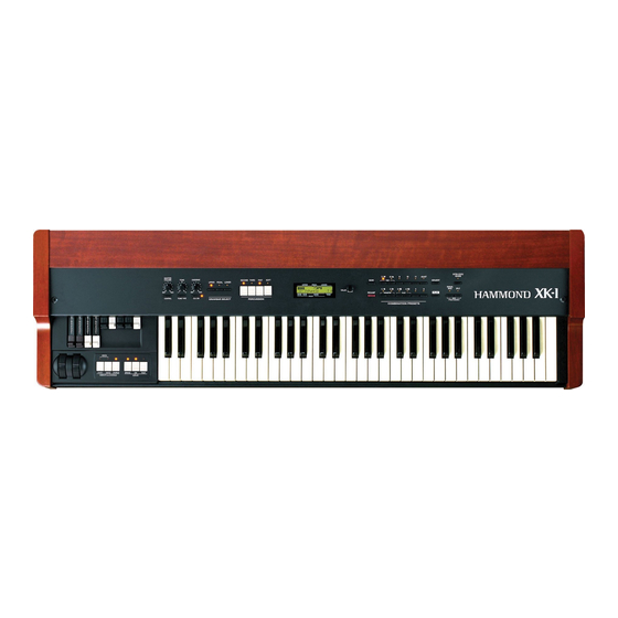
XK-1 1.Specifications Sound Generator 2 x VASE3 as Digital Tone-wheels Keyboard 61 notes Water Fall type with Velocity Harmonic Drawbars Knobs 9 Pitches Drawbar Select Tabs Upper, Pedal, Lower Waveform B-type/ Mellow/ Brite (Upper and Lower) Muted/ Normal / Synth 1/ Synth 2 (Pedal) -
Page 5: Block Diagram
XK-1 PITCH MODULA SWH-512A SWH-511A SWH-510A BENDER TION ENDBLOCK PANEL R PANEL L (VIBRATO, LESLIE) (PRESET, MENU, PLAY etc) (MASTER VOLUME, CONTROL, TONE, REVERB etc) J115 J106 J104 J105 J111 +3.3V 12.5MHz CR2032 (3V) DRAWBARS +1.26V 25MHz RESET RESET IC... -
Page 6: Test And Adjustment
XK-1 XK-1 3.TEST AND ADJUSTMENT... -
Page 7: Wiring Connection
XK-1 SWITCHING MGH-94A POWER WR-HZ133-A POWER SUPPLY INLET SWITCH J115 AES10-5 WR-HZ133-H WR-HZ133-G J111 J105 J104 J106 Ferrite core TFT-152613N with TFB-2024RS WR-HZ133-B DRAWBAR ASSY 02,0181-A26613330 02,0182-A26613340 WR-HZ133-C WHEEL ASSY FATAR KEYBOARD TP/8O J401 SWH-512A WR-HZ133-D WR-HZ133-E J301 J201 J202... -
Page 8: Wiring Chart
5.WIRING CHART XK-1 MAIN PLUG FROM TO PLUG WIRE TO PWB FUNCTION MGH-94A PIN No. & PIN NO. COLOR NAME J110 DB-1 WHT DB-209 PLUG FROM TO PLUG WIRE TO PWB FUNCTION 2 BLK PIN No. & PIN NO. COLOR... - Page 9 XK-1 PANEL SW L PLUG FROM TO PLUG WIRE TO PWB FUNCTION SWH-510A PIN No. & PIN NO. COLOR NAME PLUG FROM TO PLUG WIRE TO PWB FUNCTION PIN No. & PIN NO. COLOR NAME J201 J104-1 BRN MGH-94A COM0...
-
Page 10: Printed Wiring Board Ass'y List
6.PRINTED WIRING BOARD ASS'Y LIST XK-1 FUNCTION PWB.NAME PART No. MAIN MGH-94A 00228-25216 PANEL L SWH-510A 00225-42236 PANEL R SWH-511A 00225-42241 ENDBLOCK SWH-512A 00225-42246... - Page 11 XK-1 A[0..17] A[0..17] D[0..15] D[0..15] +3.3V S RAM CE S RAM CE PIN_CE PIN_CE DSP_CE +3.3V DSP_CE KEYSCAN_CE M CSB KEYSCAN_CE POUT_CE POUT_CE MIDI OUT M CSB MIDI OUT LM MIDI IN LM MIDI IN KEY RXD1 R115 PA1/TXD0 PC0/A0 +3.3V...
- Page 12 XK-1 D[0..15] D[0..15] KD[0.. 7] R146 KD[0.. 7] GLED0 +3.3V R144 GLED1 POUT_CE R147 GLED2 74LV32APW R145 GLED3 +3.3V KEYSCAN_CE +3.3V R148 KEYSCAN_CE C103 GLED4 0.1u C102 0.1u 74LV245APW R149 74LV574APW GLED5 U6 TD62003F :TOSHIBA ULN2003L :SPRAGUE(ALLEGRO) ULN2003D :SGS/THOMSON 100pF x 19 ULN2003ANS :T.I.
- Page 13 XK-1 C245 0.1u R173 J107 +5VAN 2.2 1/2W C159 2200u/6.3V C147 +3.3V +1.26V C148 10uF/20V OS JP10 JP11 JP12 B4B-XH-A (LF)(SN) 10uF/20V OS 0.1u CVDD DVDD CVDD 0.1u 0.1u DVDD CVDD 10uF/20V OS DVDD CVDD C141 0.1u 0.1u C144 DVDD...
- Page 14 XK-1 +5VAN 0.1u NJM4580M 0.1u FSX0 CLKX0 3300 ADMCK C165 PCM1791ADB 560pF MUTE R174 1800 R179 680 LRCK C163 R128 +3.3V 3300pF DATA R178 OUT L MUTE +5VAN NJM4580M MSEL R175 1800 C161 R127 ZEROL 10uF/50V OUT R C166 ZEROR 0.1u...
- Page 15 XK-1 SLAVE VASE3 uPD65946GJ-159-JEU PIA1 ESCKO PIA2 ELRCKO M_LRCK M_LRCK PIA3 M_SCK M_SCK PIA4 WCLKO M_DOUT M_DOUT PIA5 LRCKO ADMCK ADMCK PIA6 SCKO PK_DOUT PIA7 DOUT PK_DOUT UL_DOUT PIA8 EXOUT1 UL_DOUT PIA9 EXOUT2 PIA10 A[0..17] A[0..17] PIA11 EXIN1 EXIN2 PIA1...
- Page 16 XK-1 +3.3V FB27 R220 0.1u 8-33 EMD0 CLK IN EMD1 R221 SG-636PCE 25MHz EMD2 CLKOUT2 EMD3 +3.3V NOT USED CLKMODE0 EMD4 PLLVH EMD5 EMD6 +3.3V EXCCET103U C149 0.1u EMD7 10uF/20V OS EMD8 R49 10K EA10 D[0..15] EMD9 D[0..15] EA11 EMD10 R48 10K D[0..15]...
- Page 17 XK-1 +3.3V R155 C171 1000u/6.3V 0.1u R236 FB31 J110 +3.3V R101 FB28 2SA1588Y 1000 100pF x 9 RA12 C139 0.1u ANSEL0 C132 C133 1 3/5' ANSEL1 C134 [FRONT VIEW] UPPER DRAWBAR C135 MIDI OUT C136 1 1/3' FB29 C137 0.1u...
- Page 18 XK-1 NOT USED DK10 DK11 +3.3V DK12 DK13 DK14 RA17 DK15 8-3300 H8 CS0 AK10 AK11 DK10 AK12 DK11 +3.3V +3.3V NOT USED AK13 DK12 AK14 DK13 +3.3V AK15 DK14 AK16 DK15 0.1u J112 AK17 +3.3V AK18 H8 CS1 +3.3V...
- Page 19 XK-1 "LLA" capacitors : Low leakage current C179 220p FB3-FB65 : BLM18BD102SN1D C175 R169 R167 R164 0.01u 4700 C184 C209 C195 C180 R162 33k 220u/10V C185 C187 R156 FB17 RL1A JACK4 330p U10A 2.2u/50V LLA C188 2.2u/50V LLA OUT L...
-
Page 20: Swh-510A
XK-1 J201 COM0 COM0 COM1 LED1 LED6 COM2 COM3 COM4 GSW0 SOFT PEDAL COM1 SOFT PEDAL TO MGH-94A GSW1 GLED0 LED2 LED7 GLED1 +3.3V O.D. TONE FAST UPPER COM2 FAST UPPER LED3 LED8 S13B-PH-K-S THIRD REVERB COM3 THIRD REVERB J202... -
Page 21: Swh-511A
XK-1 J301 GLED4 GLED4 GLED3 GLED3 GLED2 GLED2 GSW5 GSW5 GSW4 GSW4 GSW3 GSW3 GSW2 GSW2 TO MGH-94A COM0 COM1 COM2 COM3 COM4 ROT A ROT B S15B-PH-K-S DATA VAL RSW1 A OUT EC12E24204A9 B OUT COM0 SW11 SW16 LED1... -
Page 22: Swh-512A
XK-1 J401 GSW5 GSW5 GLED1 GLED1 COM0 COM1 TO MGH-94A COM2 COM3 COM4 GSW6 GSW6 GLED5 GLED5 S9B-PH-K-S COM0 LED2 LESLIE ON COM1 LESLIE ON LED3 LESLIE BRAKE COM2 LESLIE BRAKE LED4 CHORUS COM3 CHORUS LED1 LED5 LESLIE FAST V2/C2... -
Page 23: Parts List 8-1~8-6
XK-1 8.PARTS LIST 1 . FI N AL AS S' Y(6 67 10- 01 101 ) Top Panel Ass'y 66710-02101 Bottom Panel Ass'y 66710-02201 Cross Recessed Tapping Screw Type3 00673-54005 (Binding Head, 4x5, ZnB) 00683-54012 Cross Recessed Tapping Screw (For Plastic) - Page 24 XK-1 Top Panel 00451-40549 WR-HZ133-E 00443-01350 Top Board 00450-40719 WR-HZ133-B 00443-01347 LCD Cover 00452-40198 Cross Recessed Tapping Screw Type1 00615-53008 Switch Board L Ass'y 66710-02103 (Binding Head, 3x8, ZnY) Switch Board R Ass'y 66710-02104 Cross Recessed Tapping Screw Type3 00673-53005...
- Page 25 XK-1 36 33 Top Panel Bracket 00451-40553 Cross Recessed Tapping Screw Type2 00653-33005 Main Board Bracket 00451-40556 (Fluted Point)(Flat Head, 3x5, ZnB) Jack Bracket 00451-40586 Cross Recessed Tapping Screw 00683-53008 MGH-94A Ass'y 00228-25216 (For Plastic)(Binding Head, 3x8, ZnB) Switching Power Supply...
- Page 26 XK-1 3 . E N DB LOCK L A SS' Y( 667 10 -02 1 0 2) Endblock L 00452-40203 Cross Recessed Tapping Screw Type2 00655-53025 Switch Board EL Ass'y 66710-02105 (Fluted Point)(Binding Head, 3x25, ZnY) WR-HZ133-C 00443-01348 Cross Recessed Tapping Screw...
- Page 27 XK-1 5 . S WI T CH BO ARD R AS S' Y(6 67 10 - 0 21 0 4) SWH-511A Ass'y 00225-42241 Keytop #2-K 00452-40206 Keytop #2-R 00452-40207 6 . S WI T CH BO ARD E L A SS 'Y( 66 7 1 0- 0 21 5 )
- Page 28 XK-1 9 . S I D E B O ARD R A SS' Y( 667 10 -02 2 03 ) Side Bracket R 00451-40552 SIde Board R 00450-40718 Endblock R 00452-40204 00615-64016 Cross Recessed Tapping Screw type1 (Truss head, 4x16, ZnY)
-
Page 29: Disassembling Procedure
XK-1 9.DISASSEMBLING PROCEDURE CAUTION:First,Disconnect ORGAN from A.C.source. 1.DISMOUNT THE BOTTOM PANEL Remove the 19 screws(Cross recessed tapping screw type3, Bind,4x5,ZnB) from the bottom panel. Remove the 8 screws(Cross recessed tapping screw for plastic, Bind,4x12,ZnB) from the bottom panel. 2.DISMOUNT THE KEYBOARD... -
Page 30: Warning
XK-1 10.WARNING WARNING Bat t ery R eplac ement Repl ac e bat t er y wi t h HITACHI MAXELL S ON Y SHENZHEN GAONENGDA BATTERY CO.,LTD C R 2 0 3 2 P ar t No . On l y . -
Page 31: Technical Description
11. XK-1 Technical description 1. Switching power supply (JRC AES10-5) This board commutates the AC power input and supplies +5V power. This +5V power is used as a MGH-94A’s power source. 2. Main, CPU, VASE, DSP and JACK on the board MGH-94A 2 CPUs, 2 VASE3s (sound generator), DSP, D/A converter and jacks are all built in the MGH-94A. - Page 32 used for UM and LM tone wheel generator and the rest are used for pedal, percussion and key-click. It switches off the tone wheel channel when the extra voice is selected. It also reads the data of U32 wave ROM and outputs the key sound which was ordered by the Main CPU, to DSP.
- Page 33 When the initialization is completed, the play mode appears on the display screen. 2. Check the soft-wear versions Please follow the below procedure to check the XK-1 soft-wear version number. a. Turn on the XK-1. b. From the play mode screen, select a [MENU/EXIT] button and see the screen changes to the MENU.
Need help?
Do you have a question about the XK-1 and is the answer not in the manual?
Questions and answers