
Related Manuals for Hammond XK-1


Summary of Contents for Hammond XK-1
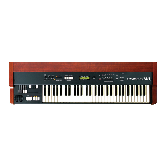
- Page 1 Model Thank you, and congratulations on your choice of a Hammond XK-1. In order to get the most out of this instrument for many years to come, first take the time to read this manual in full. Owner’s Manual...
-
Page 2: Important Safety Instructions
IMPORTANT SAFETY INSTRUCTIONS Read these instructions. Protect the power cord from being walked on or pinched, particularly at plugs, convenience receptacles, and the point Keep these instructions. where they exit from the apparatus. Heed all warnings. Only use attachments/accessories specified by the manufac- turer. - Page 3 If the fuse is lost, the plug must not be used until a replacement cover is obtained. A replacement fuse cover can be obtained from your local Hammond Dealer. IF THE FITTED MOULDED PLUG IS UNSUITABLE FOR THE SOCKET OUTLET IN YOUR HOME, THEN THE FUSE SHOULD BE REMOVED AND THE PLUG CUT OFF AND DIS- POSED OF SAFELY.
-
Page 4: Important - Please Read
IMPORTANT - PLEASE READ Your Hammond XK-1 Drawbar Keyboard is designed to give you the true and authentic sound of Hammond Harmonic Drawbars, as well as provide you a large variety of features to allow great flexibility in how you want to use the keyboard. -
Page 5: Battery Back Up
If there is no battery installed in the unit, or if the battery is compeletely dead, the Display will show: After the above message is displayed, the XK-1 will re-initialize itself, and the factory default settings will be restored. Therefore, it is a good idea to periodically save your data to CompactFlash card. -
Page 6: Table Of Contents
IMPORTANT SAFETY INSTRUCTIONS ........2 IMPORTANT - PLEASE READ ..........4 SOUND ENGINE STRUCTURE ..........30 BATTERY BACK UP .............. 5 SYSTEM STRUCTURE OF XK-1 KEYBOARD ......30 MAIN FEATURES ..............9 DRAWBARS™ ..............32 NAMES AND FUNCTIONS ..........10 WHITE DRAWBARS .............. - Page 7 SETTING THE PARAMETERS ..53 MIDI ..........75 DRAWBAR ................. 54 MIDI .................. 76 Setting the Manual (LOWER and UPPER) ..........54 What is “MIDI”? ..............76 Setting the PEDAL ..................55 MIDI TERMINALS ON THIS KEYBOARD ........76 PRESET ................56 WHAT THE MIDI CAN DO ON YOUR KEYBOARD ......
- Page 8 Owner’s Manual...
-
Page 9: Main Features
Leslie. 8-PIN LESLIE SPEAKER SOCKET. Your new XK-1 contains a 8-pin Leslie speaker socket for direct connection to Leslie 21 System Speakers. BUILT-IN EXTRA VOICE. This keyboard has built-in 8 Extra Voices such as Electric Piano and Clavi., to which you can switch from Drawbar voices or Percussion voices. -
Page 10: Names And Functions
NAMES AND FUNCTIONS Front Panel UPPER LEFT PERCUSSION MASTER VOLUME Knob 10. SECOND Button Controls the total volume. Adds 4' Percussion (Decay sound) to UPPER part. CONTROL Button 11. THIRD Button Sets up various controls. Adds 2 2/3' Percussion (Decay sound) to UPPER part. TONE Knob 12. -
Page 11: Control Panel
24 25 CONTROL PANEL UPPER RIGHT 14. DISPLAY 24. MANUAL BASS Button Displays various information. Allows Pedal sound to be played from the lowest notes on the manual keyboard. 15. VALUE Knob Adjusts the value of selected parameter. 25. SPLIT Button Divides the keyboard into two parts: UPPER and 16. -
Page 12: End Block
End Block 30 31 34 35 DRAWBARS LESLIE 27. DRAWBARS 33. LESLIE BRAKE Button Controls harmonics of part that is selected by DRAW- This button selects whether to produce sound from the BAR SELECT (7 - 9). The setting of the Drawbars is stopped rotor (=Brake) or not to use the Leslie effect (= called a “Registration”. -
Page 13: Rear Panel
If your amplifier has only a single (1) female 1/4" audio input connector (MONO input), use this Jack. 40. LINE OUT R Jack This is the Right channel output of the XK-1. Use the Left and Right output Jacks if your mixer or amplifier has stereo input. - Page 14 MIDI TERMINAL CONTROLLER TERMINAL 43. MIDI OUT Jack 46. FOOT SWITCH Jack Sends out the performance information of this keyboard. This terminal is for the Foot Switch (FS-9H - optional). You can switch the speed of the Leslie effect and the 44.
-
Page 15: Hook-Up
HOOK-UP Owner’s Manual... -
Page 16: Basic Hook-Up
BASIC HOOK-UP See the figure below for connection. Amplifiers or speakers are not mounted in this keyboard. You must connect an external amplifiers and speakers (or Powerd Speaker) in order to hear the keyboard sounds. You can also enjoy playing this keyboard by connecting Stereo Headphones to the Headphone Jack. -
Page 17: Connecting The Leslie Speaker
CONNECTING THE LESLIE SPEAKER This keyboard is equipped with a 8-Pin Leslie Connector, so you can di- rectly connect the Leslie 21 System Speaker. Make this connection with switch power OFF on the equipment. STANDARD HOOK-UP Connect the Leslie Speaker to the 8-Pin Jack on the keyboard, with the exclusive 8-Pin Leslie Cable (LC-8-7M - to be separately purchased - with the other Leslie Speaker accessories). -
Page 18: Connecting The Midi Keyboard
CONNECTING THE MIDI KEYBOARD You can upgrade this keyboard to an organ by connecting an external MIDI Key- board and pedal keyboard. MIDI Keyboard Expression Pedal MIDI Pedal V-20R Keyboard Hook-up external MIDI keyboard and pedal keyboard per the figure above. Use the MIDI Template “Seq. -
Page 19: Turn On And Play
TURN ON AND PLAY Owner’s Manual... -
Page 20: Power On
BACK-UP Your XK-1 memorizes the setting of the keyboard immediately before it is switched off. So, The keyboard will start with these settings when it is switched on again. This is called “Back-up”. The XK-1 is initially shipped from the factory with the Preset Button [ADJUST] in “pressed”... -
Page 21: Listen To The Demonstration Performance
LISTEN TO THE DEMONSTRATION PERFORMANCE In your XK-1, the demonstration performance is built in for introducing the features and sound. STEPS Touch and hold the [MANUAL BASS] and [SPLIT] Button for 2 seconds. The Display will be as shown step 2. -
Page 22: Using The Combination Presets
USING THE COMBINATION PRESETS You can record various settings to the Preset Buttons second is Number. mounted on the right-hand side of the XK-1. This is The Preset data is recorded in the Banks 1 to 12 at the called “Combination Preset”. -
Page 23: Play With The Controllers
Your performance will be more expressive, if you play using the controllers. You will see on this page how to use the controllers generally used with the electronic musical instruments. (How to use the exclusive Hammond Organ controllers is shown on the next page.) PITCH BEND WHEEL This is used to slide the pitch up or down while playing. -
Page 24: Making Your Own Sounds
Drawbars that make the fundamental tones of this keyboard. The volume gets loudest when each Drawbar is pulled out to the full length. The XK-1 gets silent when it is totally pushed in. The tones of the Drawbars gradually get higher in frequency from left to right. -
Page 25: Add Effects
ADD EFFECTS “Vibrato and Chorus” slightly changes the Drawbar pitch at a certain ratio and add warmth to VIBRATO/CHORUS the sound. [V1/C1], [V2/C2] Button Controls the Vibrato Depth and Switches on and off the Vibrato effect. The LED turns on when it is ON. -
Page 26: Divide The Keyboard Into Two Parts - Left And Right. [Split]
Divide the keyboard into two parts - left and right. [SPLIT] This keyboard has only a single manual. But you can change the setting and play it as it was a double keyboard organ, using this “SPLIT” function. [SPLIT] Button Switch on the LED by pressing the button, to “split”... -
Page 27: Storing Registrations In Combination Preset
STORING REGISTRATIONS IN COMBINATION PRESET All the afore-mentioned settings can be memorized to the Combination Preset. The data stored at the factory can also be freely re-written. EX. Memorize to “6 - 3”. While pressing the [BANK] Button, touch the Preset Button [6]. This turn on Preset BANK 6. - Page 28 Owner’s Manual...
-
Page 29: Setting Up
SETTING UP Owner’s Manual... -
Page 30: Sound Engine Structure
SOUND ENGINE STRUCTURE SYSTEM STRUCTURE OF XK-1 KEYBOARD Owner’s Manual... - Page 31 See the illustrated System Structure of your keyboard on the left page. TONE-WHEELS TONE-WHEEL SET The sound source or “engine” of Hammond Organ is the Tone-wheels. They are The Tone-wheel Sets are divided into the like the strings and pick-ups on the electric guitar. While running, each of the 96 Manual Keyboard and the Pedal Part.
-
Page 32: Drawbars
DRAWBARS™ The 9 Drawbars on this keyboard are used to make the basic sounds. Each Drawbar is marked with the numbers 1 - 8. If you push back the Drawbar until you can not see any number at all, the sound of the Drawbar is not heard. If you pull it out to the fullest position THE SOUND LEVEL is maximum. -
Page 33: White Drawbars
WHITE DRAWBARS In each Drawbar set, the white Drawbar (8') on the left end makes the basic/fundamental sound. The other white Drawbars get higher by the octave to the right. BLACK DRAWBARS The sounds of the black Drawbars, too, play important roles in building rich tones. -
Page 34: Drawbar Registration Patterns
DRAWBAR REGISTRATION PATTERNS The Drawbar Registration is matched by the number value of each Drawbar as shown below on right side of Drawbar settings name. However, it is rather reasonable to remember the typical combinations of the 9 Drawbars by their forms/shapes. Flute family (2 step pattern) Accompaniment Flute 8' I 00 8460 000... - Page 35 Diapason family (check mark pattern) Accomp. Diapason 8' 00 8874 210 Chorus Diapason 8' 00 8686 310 Diapason 8' 00 7785 321 Echo Diapason 8' 00 4434 210 Harmonic Diapason 16' 85 8524 100 Harmonic Diapason 8' 00 8877 760 Harmonic Diapason 4' 00 0606 045 Horn Diapason 8'...
-
Page 36: Drawbar Select
DRAWBAR SELECT ASSIGN THE DRAWBARS FOR EACH PART Touch On this keyboard, there are 3 Parts: UPPER, LOWER and There is one set of Drawbars on this keyboard, though this PEDAL, and each of them has the corresponding Drawbars. keyboard has 3 Parts. Use Drawbar Select Buttons for assign- The manual on the keyboard is usually assigned to the UPPER ment of the Drawbars for each of the Parts. -
Page 37: Percussion
PERCUSSION The Percussion attack sound is a Hammond exclusive. Percussion is usually used with the Drawbar sound. [SECOND] BUTTON DECAY The second harmonic, or 4' Drawbar decay, is added to the UPPER Part. To use this, press the [SECOND] button , and the LED will light. -
Page 38: Vibrato/Chorus
VIBRATO/CHORUS VIBRATO adds warmth to the tone, by slightly changing the Drawbar pitch at a certain speed. You can also add richness to the sound by mixing the Vibrato sound with the fundamental (= Chorus Effect). [V1/C1], [V2/C2] BUTTON BUTTONS AND STATUS This switches ON/OFF Vibrato/Chorus Effects and sets the its depth. -
Page 39: Overdrive
OVERDRIVE The Overdrive produces the distorted sound like that of an over-driven amplifier. By changing the amount of the Drive, various Tube Sounds are obtained, from the unclipped clean to the hard-distorted fuzzy, raspy Overdrive sound. [O.D. ON] BUTTON This button switches on/off the Overdrive Effect. Press this button to switch on the LED, and get the Overdrive Effct. -
Page 40: Leslie
LESLIE LESLIE EFFECT is the simulated sound of rotating speakers. If you connect the real Leslie speakers to this keyboard, it controls those (speakers) [ON] BUTTON If you touch this button, the LED will light, and the rotor starts turning. Also the voice is heard thru the rotary channel. -
Page 41: Equalizer & Reverb
EQUALIZER & REVERB The Equalizer and the Reverb effects give the final touch to the tone. The Equalizer regulates the tone, and the Reverb adds the resonance of the hall performance. You can control these functions with the panel buttons and knobs EQUALIZER [TONE] KNOB Can be setup to control any one of the three tone types. -
Page 42: Combination Presets
Drawbars, even while using the buttons [1] to [11]. COMBINATION PRESETS On the original B-3 organ, the preset keys only stored drawbar registration information. On the XK-1 however, in addition to drawbar registration, you can store many various parameters to a preset. Thus the name “Combination Preset”. -
Page 43: Name The Combination Presets
NAME THE COMBINATION PRESETS Go to the MENU. Touch the [MENU/EXIT] button. The MENU mode will be displayed. Go to PAGE A. If the PAGE A is not displayed, touch the [PAGE] button and go to PAGE A. Go to the PRESET FUNCTION mode. Touch the [2] PRESET button and go to the PRESET FUNC- TION mode. -
Page 44: Record A New The Combination Preset
RECORD A NEW THE COMBINATION PRESET EXAMPLE: Record into “6-3”. Go to the PLAY mode. If the display is not in PLAY mode, touch the [PLAY] button to back to the PLAY mode. This operation is not necessary, if the display is in PLAY mode. Select the Bank. -
Page 45: Using The Control Panel
USING THE CONTROL PANEL Owner’s Manual... -
Page 46: Operation Control Panel
OPERATION CONTROL PANEL You now know you can control many settings by using the buttons and knobs on your keyboard. You can do even finer settings like the delicate speed of the Leslie Effect or the MIDI equipment, using the display buttons on the Control Panel. -
Page 47: Play Mode
PLAY MODE The PLAY MODE is the basic display for all the operations. The necessary infor- mations for the normal play will be displayed. There are two types of PLAY MODE screens to display the Drawbar Registration. One is by showing the length of the Drawbars and the other by digits. How to show this display: Immediately after powered ON and the start up process is complete, the PLAY mode is displayed. -
Page 48: Menu Mode
MENU MODE The MENU mode is the path for each function. How to show this display: Touch the [MENU] button. There are several pages which contains many various FUNCTION displays. Move from page to page and find the item where you want to go and touch the numbered button to see the desired display. -
Page 49: Function Mode
FUNCTION MODE The FUNCTION MODE is for making each setting and adjustment. There are many displays, but the basic operation is the same. HOW TO READ THE DISPLAY This shows there are PAGEs above (or below). PARAMETER This shows there is a PAGE on the right (or on the left). -
Page 50: Example Of Operation
Example of operation: Adjusting the DECAY TIME of the Percussion [FAST] Go to the MENU Mode. Touch the [MENU] button. The [MENU] mode is displayed. Select the PAGE. Search for the PERCUS page, using the [PAGE] button. “PERCUS” is on PAGE B. So select PAGE [B]. - Page 51 Change the value. Decrease the value, using the [VALUE] button or the [VALUE] knob on the left. NOTE: Repeat the operation 1 - 5, if you want to change other parameters, too. Back to PLAY mode. Touch the [PLAY] button to return to the PLAY mode.
-
Page 52: Short Cut To The Function Mode
SHORT CUT TO THE FUNCTION MODE Each button on the panel has a “SHORT-CUT” capability, so that you can easily go to each Function mode. By holding down the button, you can easily go to the desired mode display. The “SHORT-CUT” mode can save time by going directry to the parmeters you want to change. -
Page 53: Setting The Parameters
SETTING THE PARAMETERS Owner’s Manual... -
Page 54: Drawbar
DRAWBAR In this mode, you can set the Parameter relating to the Drawbar sound of each part. To locate the Drawbar mode: Touch the [MENU/EXIT] button and display MENU, touch the [PAGE] button and select PAGE A and choose [1] DRAWBAR. Setting the Manual (LOWER and UPPER) TONE-WHEEL SET TONE-WHEEL... -
Page 55: Setting The Pedal
FOLD-BACK - HIGH This allows you to set which key the 1' Drawbar starts to FOLD-BACK (= repeat the same octave) in the upper-most range. The set range is 4G - 5C. NOTE: The FOLD-BACK can be set not only on the 1' but also 1 1/3', 1 3/5', 2' and 2 2/3' Drawbars. -
Page 56: Preset
PRESET In this mode, you can name the Combination Presets. To locate this mode: Touch the [MENU/EXIT] button and display MENU, then touch the [PAGE] button to select PAGE A and touch the [2] PRESET button. PRESET NAME PRESET LOAD - INTERNAL ZONE (B) This allows you to determine whether or not to recall the Preset Name (P) Parameters relating to the Internal Zone such as SPLIT or... -
Page 57: Effective Use Of Link-Lower/Pedal
EFFECTIVE USE OF LINK-LOWER/PEDAL This is the function to switch/record only from the connected MIDI equipment, and not to operate the Preset for LOWER and PEDAL on this keyboard. The Preset Keys on B-3/C-3 are independent, key by key, and so they were operated independently. -
Page 58: Control
CONTROL In this mode, you can do the setting relating to each mode. controller. To locate this mode: You may change the roles of several knobs and switches Touch the [MENU/EXIT] button and display the MENU and mounted on this keyboard. Also, on the rear panel are select PAGE A by the [PAGE] button, and then touch the two terminals for connecting the Foot-switch and the [4] CONTROL button. -
Page 59: Modulation
When the value of this parameter is “OF”, the pitch goes down and the sound gradu- ally fades out. MODULATION MODULATION - LESLIE (P) BRAKE ON MODULATION Assigns the Modulation Wheel to Leslie Speed Function. If you want to “Brake” the Leslie effect by pull ON: If you push back and pull foward the Modulation Wheel, the speed of Leslie forward the modulation wheel, set the Slow effect changes fast to slow continuously. -
Page 60: Foot Switch
FOOT SWITCH 15. FOOT-SWITCH - TIP (G) This is for setting the function for the Foot Switch 1 terminal. If you are using the Foot Switch with the stereo plug, this sets the function on the tip DAMPER side. OFF: The word “Damper”... -
Page 61: Extra Voice / Reverb
EXTRA VOICE / REVERB 17. EXTRA VOICE / REVERB (G) This is for setting the function for the [EXTRA VOICE / REVERB] BUTTON. EXVOICE: Switches the Organ sound and Extra Voice. REVERB: Switches On/Off the Reverb Effect. PEDAL SUS: Switches On/Off Sustain of the PEDAL. EX. -
Page 62: Adjusting The Expression Pedal
ADJUSTING THE EXPRESSION PEDAL When you use the expression pedal V-20R, we suggest you follow the adjust procedure as below. Set to “0” Plug-in the Expression Pedal V-20R to the this keyboard, set Step on the Expression Pedal to the toe side maximum. the Minimum Volume to Zero. -
Page 63: Tune
TUNE In this mode, you can tune and transpose for playing in ensemble with the other instruments. To locate to this mode: Touch the [MENU/EXIT] button (MENU will displayed), select PAGE A by the [PAGE] button and touch the [3] TUNE button. TRANSPOSE You can transpose the entire keyboard in semi-tone increments. -
Page 64: Custom Tonewheels
CUSTOM TONEWHEELS In this mode, you can select and regulate each the Tone-Wheel Set for the Manual Keyboard. We call this “CUSTOM TONEWHEELS”. The typical 3 (or 4) types of settings are recorded when delivered from the factory. To locate this mode: Touch the [MENU/EXIT] button and display MENU, select PAGE B by the [PAGE] button, and then touch either [1] B-type, [2] Mellow, or [3] Brite button for the desired Tonewheel Set. -
Page 65: Percuss (Percussion)
PERCUSS (PERCUSSion) In this mode, you can set the parameter of the PERCUSSION sound. To locate this mode: Touch the [MENU/EXIT] button and display MENU, then select PAGE B by the [PAGE] button and touch [4] PERCUSS button. Or, hold down either [SECOND],[THIRD],[FAST],or [SOFT] button for a certain length of time. -
Page 66: Leslie
LESLIE In this mode, you can create your own setting for the Combination Presets. built-in Leslie Effect. To locate this mode: There are many parameters for the built-in Leslie Effect, Touch the [MENU/EXIT] button to display the MENU. and so you create various settings, but not per each Then select PAGE C by the [PAGE] button and touch [3] Combination Preset independently. - Page 67 HORN LEVEL 12. BASS LEVEL The Volume of each Rotor is set. The setting range is 0 to -12dB. RISE TIME - HORN 13. RISE TIME - BASS Here the Time is set for the Rotor to reach the Fast Speed, when you go from Slow or Break to Fast.
-
Page 68: Record The Cabinets
RECORD THE CABINETS The Leslie parameters (2 - 17 of the previous paragraph) can be recorded with the Cabinet Numbers, and you can choose and use them in each Combination Preset. Enter the name for the Cabinet as you want. Touch the [REC/JUMP] button in the setting mode of the Leslie Parameter. -
Page 69: Od/Vib (Overdrive / Vibrato)
OD/VIB (OverDrive / VIBrato) In this mode, you can change the setting relating to each Effect for Overdrive and Vibrato/Chorus. To locate this mode: Touch the [MENU/EXIT] button to display the MENU, select PAGE C by the [PAGE] button, and then touch the [1] OD/VIB button. Or, hold down the [O.D. -
Page 70: Equaliz (Equalizer)
EQUALIZ (EQUALIZer) In this mode, you can change the setting for the Equalizer. Equalizer is an effect to adjust the tonal quality. The built-in Equalizer consists of 3 bands. With the 3 bands from bass to treble, you can boost or cut them. To locate this mode: Touch the [MENU/EXIT] button for the MENU, select PAGE C by the [PAGE] button, and then touch the [2] EQUALIZE button. -
Page 71: Reverb
REVERB In this mode, you can change the setting for the REVERB EFFECT. To locate this mode: Touch the [MENU/EXIT] button for the MENU display, select PAGE C by the [PAGE] button, and then touch the [4] REVERB button. Or, hold down the [EXTRA VOICE / REVERB] button for a while . REVERB ON DELAY FEEDBACK This parameter switches on/off the Reverb Effect. -
Page 72: Default
DEFAULT In this mode, you can return entirely or partially to the default setting as set at the factory. To locate this mode: Touch the [MENU/EXIT] button for the MENU display, select PAGE D by the [PAGE] button, and then touch the [3] DEFAULT button. To initialize each parameter, touch the [PARAM] button and then [4] OK. -
Page 73: System
SYSTEM In this mode, display information of this keyboard. To locate this mode: Touch the [MENU/EXIT] button to display the MENU, select PAGE D by the [PAGE] button, and then touch the [4] SYSTEM button. VERSION - MAIN PROGRAM VERSION - TONE INFORMATION VERSION - DEMO SONG VERSION - KEY SCAN PROGRAM VERSION - BOOT PROGRAM... -
Page 74: Exvoice (Extra Voice)
EXVOICE (EXtra VOICE) In this mode, you can set the EXTRA VOICE. Your keyboard has built-in tones such as Electric Piano and Clavi., to which you can switch from Drawbar or Percussion voice. To locate this mode: Touch the [MENU/EXIT] button to display the MENU, select PAGE F by the [PAGE] button, and then touch the [1] EXVOICE button. -
Page 75: Midi
MIDI Owner’s Manual... -
Page 76: Midi
MIDI What is “MIDI”? MIDI stands for Musical Instrument Digital Interface. (The capital letters of these four words.) MIDI is for exchanging the performance information between an electronic musical instrument and a sequencer etc. MIDI is an international standard, by which instruments made by different manufacturers can be connected to communitate with each other. -
Page 77: Midi Channel
MIDI CHANNEL MIDI has the “MIDI CHANNELS” 1 - 16. Thus, you can send your playing information divided into 16 channels through one MIDI cable. However, the channel must match between the sender and the receiver. Otherwise, you can not “hear” what the other “says”. MAJOR MIDI MESSAGE The MIDI infomation is grouped into the channel message for each of the 16 channels and the system message for the total channels. -
Page 78: Midi Structure Of This Keyboard
EX. ZONE 1, EX. ZONE 2, EX. ZONE 3 You can use your XK-1 as a simple Master Keyboard, by assigning the range of the full scale keyboard through the channel to control each External MIDI equipment. You can have different settings for each Combination Preset. -
Page 79: Expanding The Keyboard
EXPANDING THE KEYBOARD This is the method how to connect the XK-1 to the MIDI keyboard and play on the full manual (3 keyboard) instrument. MIDI Keyboard MIDI Pedal Expression Pedal Keyboard Hook up as shown above. Recall “Seq. Record” by using a MIDI template. -
Page 80: Recording And Playing
Connect the MIDI OUT to the MIDI IN of the Sequenser. Recall “Seq. Record” by using a MIDI template. By this, the output of the XK-1 is sent to MIDI channels 1, 2 and 3. MIDI Pedal Set the Keyboard Channel if you want. -
Page 81: Controlling The External Midi Equipments
CONTROLLING THE EXTERNAL MIDI EQUIPMENTS You can control External MIDI Equipment such as a Sound Modules, upto 3 Zones by your XK-1. Hook up as illustrated above. Connect the MIDI OUT to the MIDI IN of the Equipment you want to control. -
Page 82: Zones
ZONES To control the external sound module, a certain range of To locate this mode: the manual keyboard of this keyboard is used for that. Touch the [MENU/EXIT] button to display the MENU, select PAGE D by the [PAGE] button, and then touch [1] Each of them is called the “EXTERNAL ZONE”. - Page 83 13. NOTE - VOLUME 19. MESSAGE - PITCH BEND This is for setting the volume (= Control Change #7) of this 20. MESSAGE - DAMPER zone. However, the set value will be null, if the CC# (item #18) 21. MESSAGE - MODULATION is at “7.VOL”.
-
Page 84: Midi
This is for setting the behavior of the two MIDI IN terminals. UPPER / PEDAL: The Leslie Parameters will be sent out on XK-1 original Each MIDI IN terminal acts as a receiving terminal for the NRPN address and data. -
Page 85: Keyboard Channel
RECEIVE DUMP DETAILS OF THE MIDI TEMPLATES This is for determining whether or not to receive the For the details at each Template's call MEMORY DUMP. out, refer to the Appendix. On this module, you can transmit/receive the current settings by the System Exclusive Message as the MEMORY DUMP, but you must switch this OFF, if you do not want the settings of this keyboard to be changed. - Page 86 Owner’s Manual...
-
Page 87: Trouble Shooting
TROUBLE SHOOTING Owner’s Manual... -
Page 88: Trouble Shooting
TROUBLE SHOOTING Malfunction of the buttons, the keys, etc. Turn off the POWER switch once, then turn it on again. If this procedure is not successful, turn off the POWER switch once. Then, while pressing [REC/JUMP] button, turn the POWER switch on again. (Note that, in this case, all parameters return to their factory-preset status.) Malfunction of the Combination Presets. -
Page 89: Appendix
APPENDIX... -
Page 90: Custom Tone-Wheel
Appendix Custom Tone-wheel B-Type Real B-3 This template faithfully simulates the classic model, B-3. It contains low motor hum and some leakage noise. 80's Clean This template simulates the B-3 sounds in the 80’s. It contains reduced leakage noise. Noisy This template is for passing all sounds of picked-up signal. -
Page 91: Midi Templates
Appendix MIDI Templates Template Data Range Seq. Record Seq. Play Use Ex.Zone Lower / Pedal , MIDI In Lower / Pedal In1 / In2 Lower / Pedal In1 / In2 Local Control Off/On NRPN Off/On Messages Program Chg. Off/On Registration Off/On Wheel Off/On... - Page 92 Appendix [Hammond Combo Organ] Date: 15-Oct-2005 Model: XK-1 MIDI Implementation Chart Version: 1.0 Function Transmitted Recognized Remarks Default Basic Upper Channel *1 Channel Changed 1 - 16 1 - 16 Default Mode Messages Altered ***** Note 12 - 120 36 - 96...
-
Page 93: Part And Midi Messages
Appendix Part and MIDI Messages External Upper Lower Pedal Zone Keyboard Keyboard Keyboard (Tx. Only) Note Pitch Bend O *1 Modulation Volume, Pan (7, 10) Expression (11) O *2 O *3 Hold 1 (64) Drawbar Reg. CC#80 CC#81 CC#82 Spring Shock (16) (100, 101) O *4... -
Page 94: Midi Information
Appendix MIDI Information [Channel Voice Message] Spring Shock Status 2nd Byte 3rd Byte Note Off Status 2nd Byte 3rd Byte n=MIDI Channel Number: 0 - F(Ch.1 - 16) vv=Any: n=MIDI Channel Number: 0 - F(Ch.1 - 16) Hold 1 kk=Note Number: 00 - 7F(0 - 127) Status 2nd Byte 3rd Byte... -
Page 95: Drawbar Data List
Appendix NRPN MSB/LSB RPN MSB/LSB Status 2nd Byte 3rd Byte Status 2nd Byte 3rd Byte (MSB) (MSB) (LSB) (LSB) n=MIDI Channel Number: 0 - F(Ch.1 - 16) n=MIDI Channel Number: 0 - F(Ch.1 - 16) mm=Upper Byte of the Parameter Number designated by NRPN[MSB]. mm=Upper Byte of the Parameter Number designated by RPN[MSB]. -
Page 96: System Exclusive Message
Appendix System Exclusive Message Memory Dump Mode Setting Exclusive Message 1.Each Packet Full Parameters Reset System Exclusive System Exclusive SUZUKI ID SUZUKI ID Device ID Device ID for DT1 Model ID MSB Model ID for DT1 Model ID LSB Command: DT1 Command: Data Packet Address MSB [TYPE]... -
Page 97: Global Parameters
Appendix Global Parameters Category Global Parameters NRPN DATA Parameter Default Description (62) (63) (06) 00 3A - 40 - 46 Transpose Tune (-6 - 0 - 6) Master Tune 02 032E - 0338 - 0342 0338 (430 - 440 - 450) Expression Source 00 00 - 02... -
Page 98: Preset Parameters
Appendix Preset Parameters Category Combination Preset Parameters Category Combination Preset Parameters NRPN DATA NRPN DATA Parameter Parameter P. load P. load (62) (63) (06) (62) (63) (06) Name 10 Characters Internal Split On 00 00, 01 (Off/On) always Zone Manual Bass On 01 00, 01 (Off/On) Drawbar Leslie On... - Page 99 Appendix Category Combination Preset Parameters Category Lower Preset Parameters NRPN DATA NRPN DATA Parameter Parameter P. load P. load (62) (63) (06) (62) (63) (06) Upper/ Voice Type 00 00 - 02 Lower 00: B-Type Lower Drawbars 5 1/3' 01: Mellow Drawbar 02: Brite Voice...
-
Page 100: Leslie Parameters
Appendix Leslie Parameters Category Leslie Parameters NRPN on XK NRPN on 21 DATA Parameter Default (62) (63) (62) (63) (06) Name (10 Characters) Cabinet #1 - 8 Slow Speed Horn 00 00 - 63(0, 24 - 318rpm) 05 (36rpm) Slow Speed Bass 01 00 - 63(0, 24 - 318rpm) 05 (36rpm) 02 00 - 1A(0, 375 - 453rpm) 07 (393rpm) -
Page 101: Combi. And Bank/Program Messages
Appendix Combi. and Bank/Program Messages Adjust Owner’s Manual... -
Page 102: Specifications
Appendix Specifications Sound Generator Combination Presets 2 x VASE III as 12 banks x 11 Numbers Digital Tone-wheels + Adjust Switchable: Link/Independent Keyboard Controllers 61 notes Water Fall type with Velocity Switches Harmonic Drawbars Power On / Off Rotary Controllers Knobs Master Volume 9 Pitches... -
Page 103: Demonstration Songs And Composers
Deryl Winston is a long time resident of San Diego. Liberation Hammond Suzuki. Besides participating at dealer He began playing the Hammond Organ at age 14 while promotions, national conventions, concerts, and Takanobu Masuda still living in his native home of Seattle Washington. -
Page 104: Factory Presets
Factory Presets Adjust... - Page 105 HAMMOND Authorized Service Center together with a copy of your sales slip or similar proof- of-purchase, and the authorized service center will repair the defective unit without charge for parts or labor.
- Page 106 This warranty gives you specific legal rights which vary from state to state. (Available in U.S.A. only) IMPORTANT: THIS IS YOUR HAMMOND WARRANTY REGISTRATION. Fill out NOW and mail-DON’T DE- LAY! To receive the protection of this limited one-year warranty, you MUST return registration card within 10 days after the date of purchase.
-
Page 107: Service
Manual, total accuracy cannot be guaranteed. Should the owner require further assistance, inquiries should first be made to your Authorized Hammond Dealer. If you still need further assistance, contact Hammond at the following addresses:... - Page 108 HAMMOND SUZUKI, LTD., Hamamatsu, Japan Printed in China 00457-40113 V1.00-051222...
Need help?
Do you have a question about the XK-1 and is the answer not in the manual?
Questions and answers