Siemens sinamics g120 Operating Instructions Manual
Cu250s-2 control units
Hide thumbs
Also See for sinamics g120:
- List manual (1256 pages) ,
- Manual (732 pages) ,
- Operating instructions manual (550 pages)
Table of Contents
Advertisement
Quick Links
CU250S-2 Control Units
SINAMICS
SINAMICS G120
CU250S-2 Control Units
Compact Operating Instructions
Edition 01/2016
01/2016
A5E37058195B AA
Fundamental safety
___________________
instructions
___________________
Scope of delivery
___________________
Installing
___________________
Commissioning
___________________
More information
1
2
3
4
5
Advertisement
Table of Contents

Related Manuals for Siemens sinamics g120


Summary of Contents for Siemens sinamics g120
- Page 1 Fundamental safety ___________________ CU250S-2 Control Units instructions ___________________ Scope of delivery ___________________ SINAMICS Installing ___________________ Commissioning SINAMICS G120 CU250S-2 Control Units ___________________ More information Compact Operating Instructions Edition 01/2016 01/2016 A5E37058195B AA...
- Page 2 Note the following: WARNING Siemens products may only be used for the applications described in the catalog and in the relevant technical documentation. If products and components from other manufacturers are used, these must be recommended or approved by Siemens. Proper transport, storage, installation, assembly, commissioning, operation and maintenance are required to ensure that the products operate safely and without any problems.
-
Page 3: Table Of Contents
More information ........................... 29 Overview of the manuals ......................29 Technical support ........................30 This manual describes how you install a SINAMICS G120 converter with CU250S-2 Control Unit and commission it. What is the meaning of the symbols in the manual? Reference to further information in the manual An operating instruction starts here. -
Page 4: Fundamental Safety Instructions
Fundamental safety instructions General safety instructions WARNING Risk of death if the safety instructions and remaining risks are not carefully observed If the safety instructions and residual risks are not observed in the associated hardware documentation, accidents involving severe injuries or death can occur. •... -
Page 5: Industrial Security
Siemens recommends strongly that you regularly check for product updates. For the secure operation of Siemens products and solutions, it is necessary to take suitable preventive action (e.g. cell protection concept) and integrate each component into a holistic, state-of-the-art industrial security concept. -
Page 6: Scope Of Delivery
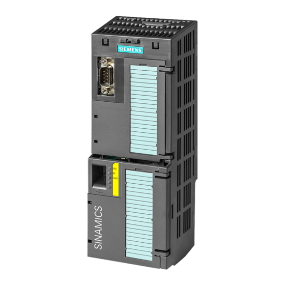
● A CU250S-2 Control Unit ready for operation with installed firmware. Options for upgrading and downgrading the firmware can be found on the Internet: Firmware (http://support.automation.siemens.com/WW/news/en/67364620) The fieldbus interface of the Control Unit depends on the order number. The order number, the designation and the version of the hardware (e.g. 02) ①... -
Page 7: Installing
Installing Installing the Control Unit Installing the Control Unit - General Each Power Module has an appropriate holder for the Control Unit and a release mechanism. Inserting the Control Unit Proceed as follows to plug the Control Unit onto a Power Module: 1. -
Page 8: Overview Of The Interfaces
Installing 3.2 Overview of the interfaces Overview of the interfaces To access the interfaces at the front of the Control Unit, you must unplug the Operator Panel (if one is being used) and open the front doors. ① Terminal strips ②... - Page 9 Installing 3.2 Overview of the interfaces Interfaces at the lower side of the Control Unit Table 3- 1 Permissible encoders on the DRIVE-CLiQ interface X100 DRIVE-CLiQ Resolver HTL Endat 2.1 sin/cos encoder encoder encoder encoder encoder Direct connection ✓ Connection via Sensor Module SMC10, ✓...
-
Page 10: Terminal Strips Behind The Upper Front Door
Installing 3.3 Terminal strips behind the upper front door Terminal strips behind the upper front door All terminals with reference potential "GND" are connected with one another in the inverter. Terminals 31, 32 Connection of the optional 24 V supply has the following advantages: The Control Unit remains in operation after disconnection of the Power Module from the line sup- •... - Page 11 Installing 3.3 Terminal strips behind the upper front door All terminals with reference potential "GND" are connected with one another in the inverter. Reference potentials for DI 1, DI 3 und DI 5, electrically isolated from "GND" Reference potential for DI 0, DI 2, DI 4 and DI 6, electrically isolated from "GND" Reference potential for DI 16 …...
- Page 12 Installing 3.3 Terminal strips behind the upper front door Factory setting of the terminal strips The factory setting of the terminals depends on the Control Unit. Control Units with USS or CANopen interface The fieldbus interface is not active. Image 3-3 Factory setting of the CU250S-2 and CU250S-2 CAN Control Units CU250S-2 Control Units Compact Operating Instructions, 01/2016, A5E37058195B AA...
- Page 13 Installing 3.3 Terminal strips behind the upper front door Control Units with PROFIBUS or PROFINET interface The function of the fieldbus interface depends on DI 3. Image 3-4 Factory setting of the CU250S-2 DP and CU250S-2 PN Control Units Changing the function of the terminals The function of the terminals marked in color in the two figures above, can be set.
-
Page 14: Operator Panels
Further default settings can be found in the Operating Instructions: Manuals for the Control Unit (http://support.automation.siemens.com/WW/view/en/30563628/133300) Wiring the terminal strip in compliance with EMC 1. If you use shielded cables, then you must connect the shield to the mounting plate of the control cabinet or with the shield support of the inverter through a good electrical connection and a large surface area. -
Page 15: Commissioning
Connecting cable (3 m) between PC and inverter: Article number 6SL3255-0AA00-2CA0 DVD article number STARTER: 6SL3072-0AA00-0AG0 Startdrive: 6SL3072-4CA02-1XG0 System requirements and download: STARTER (http://support.automation.siemens.com/WW/view/en/26233208) Startdrive (http://support.automation.siemens.com/WW/view/en/68034568) Help regarding operation: STARTER videos (http://www.automation.siemens.com/mcms/mc-drives/en/low-voltage- inverter/sinamics-g120/videos/Pages/videos.aspx) Startdrive tutorial (http://support.automation.siemens.com/WW/view/en/73598459) CU250S-2 Control Units Compact Operating Instructions, 01/2016, A5E37058195B AA... -
Page 16: Commissioning With Starter Or Startdrive
Commissioning 4.1 Commissioning with STARTER or Startdrive Commissioning with STARTER or Startdrive Creating a new project Procedure To create a new project, proceed as follows: 1. In the menu, select "Project" → "New…". 2. Specify a name of your choice for the project. You have created a new project. - Page 17 Commissioning 4.1 Commissioning with STARTER or Startdrive 6. When the USB interface is appropriately set, then the "Accessible nodes" screen form shows the inverters that can be accessed. Image 4-3 Inverters found in STARTER Image 4-4 Inverters found in Startdrive If you have not correctly set the USB interface, then the following "No additional nodes found"...
- Page 18 Commissioning 4.1 Commissioning with STARTER or Startdrive Setting the USB interface in STARTER Procedure Proceed as follows to set the USB interface in STARTER: 1. Set the "Access point" to "DEVICE (STARTER, Scout)" and the "PG/PC interface" to "S7USB". 2. Press the "Update" button. You have set the USB interface.
- Page 19 Commissioning 4.1 Commissioning with STARTER or Startdrive Starting the configuration Procedure To start the configuration, proceed as follows: 1. In STARTER select the drive you wish to commission. 2. Start the wizard for the device configuration: Image 4-5 Start the configuration in STARTER Image 4-6 Start the configuration in Startdrive You have started the configuration.
- Page 20 Commissioning 4.1 Commissioning with STARTER or Startdrive Loading the configured data into the drive Procedure with STARTER Proceed as follows to load the configured data into the drive: 1. Select your drive. 2. Go online: STARTER compares your configuration with the real inverter. STARTER signals any differences in the "Online/offline comparison".
- Page 21 Commissioning 4.1 Commissioning with STARTER or Startdrive Identify motor data WARNING Danger to life from machine movements while motor data identification is in progress The stationary measurement can turn the motor a number of revolutions. The rotating measurement accelerates the motor up to the rated speed. Secure dangerous machine parts before starting motor data identification: •...
- Page 22 Commissioning 4.1 Commissioning with STARTER or Startdrive 4. Switch on the motor. The inverter starts the motor data identification. This measurement can take several minutes. Depending on the setting, after motor data identification has been completed, the inverter switches off the motor - or it accelerates it to the currently set setpoint. 5.
- Page 23 Commissioning 4.1 Commissioning with STARTER or Startdrive 6. Relinquish the master control after the motor data identification. 7. Save the settings in the inverter (RAM → EEPROM): You have completed the motor data identification. Self-optimization of the speed control If you have selected not only motor data identification but also rotating measurement with self-optimization of the speed control, you must switch on the motor again as described above and wait for the optimization run to finish.
-
Page 24: Connecting The Inverter To The Fieldbus
Connecting the inverter to the fieldbus Where can I find instructions for the fieldbus connection of the inverter? Instructions for connecting to a fieldbus can be downloaded from the Internet: ● Application examples (http://support.automation.siemens.com/WW/view/en/60733299) ● Operating Instructions: CU250S-2 operating instructions (https://support.industry.siemens.com/cs/ww/en/view/109478829) ●... - Page 25 Commissioning 4.2 Connecting the inverter to the fieldbus Meaning Explanation 0 = Disable RFG The inverter immediately sets its ramp-function generator output to 0. 1 = Do not disable RFG The ramp-function generator can be enabled. 0 = Stop RFG The output of the ramp-function generator stops at the actual value.
-
Page 26: Frequently Required Parameters
Alternative to download Generic Station De- Internet: GSD and GSDML are saved in the scription (GSD) for (http://support.automation.siemens inverter. The inverter writes its GSD or PROFIBUS .com/WW/view/en/23450835) GSDML to the memory card once you insert this card in the inverter and set... - Page 27 Commissioning 4.3 Frequently required parameters Parameter Explanation r0722 Status of digital inputs Terminal 5 DI 0 Selection of possible settings: Terminals 6, 64 DI 1 p0840 ON/OFF (OFF1) p1110 inhibit negative direction p0844 no coast down (OFF2) p1111 inhibit positive direction Terminal 7 DI 2 p0848 no quick stop (OFF3)
- Page 28 Commissioning 4.3 Frequently required parameters Parameter Explanation p0922 PROFIdrive telegram selection p1001 Fixed speed setpoint 1 p1002 Fixed speed setpoint 2 p1003 Fixed speed setpoint 3 p1004 Fixed speed setpoint 4 p1058 Jog 1 speed setpoint p1059 Jog 2 speed setpoint p1070 Main setpoint Selection of possible settings:...
-
Page 29: More Information
Installing, commissioning and maintaining the inverter. Advanced commissioning. ● EMC installation guideline (http://support.automation.siemens.com/WW/view/en/60612658) EMC-compliant control cabinet design, potential equalization and cable routing. ● CU250S-2 List Manual (https://support.industry.siemens.com/cs/ww/en/view/109477253) Parameter list, alarms and faults. Graphic function diagrams. ● "Fieldbus" function manual (https://support.industry.siemens.com/cs/ww/en/view/109477369) Configuring fieldbuses. -
Page 30: Technical Support
● Power Module Installation Manual (https://support.industry.siemens.com/cs/ww/en/ps/13224/man) Installing Power Modules, reactors and filters. Technical data, maintenance. ● Accessories manual (https://support.industry.siemens.com/cs/ww/en/ps/13225/man) Installation descriptions for inverter components, e.g. line reactors and line filters. The printed installation descriptions are supplied together with the components.
Need help?
Do you have a question about the sinamics g120 and is the answer not in the manual?
Questions and answers