Siko AP04 User Manual
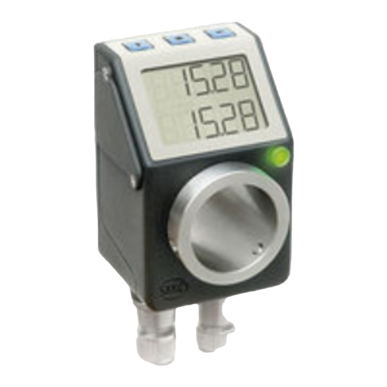
Absolute position indicator
Hide thumbs
Also See for AP04:
- Installation instructions manual (40 pages) ,
- User manual (38 pages) ,
- User information (12 pages)
Table of Contents
Advertisement
Advertisement
Table of Contents

Related Manuals for Siko AP04


Summary of Contents for Siko AP04
- Page 1 User manual Absolute Position Indicator with - interface AP04...
-
Page 2: Table Of Contents
Node number (node ID)______________________________________________________________ 13 Transmission of process data ________________________________________________ 13 From the AP04 to the bus master ( position value + status byte) ______________________________ 13 From bus master to AP04 (target value) _________________________________________________ 14 Transfer of the SDO data (parameterization) ____________________________________ 15... - Page 3 Object 5F15h (Loop direction)_________________________________________________________ 39 Object 5F16h (Read target value) ______________________________________________________ 40 Object 5F18h (External Heartbeat source) _______________________________________________ 40 Object 5F19h (AP04 status) __________________________________________________________ 40 Object 6000h (Operating Parameters) __________________________________________________ 41 Object 6001h, (Display per revolution, APU)______________________________________________ 41 Object 6002h (Total Measuring Range [Total of measurement steps]) _________________________ 42...
-
Page 4: General Informaton
1. General Informaton This user manual is valid for the absolute position indicator AP04 with firmware version 1.03 or higher and is intended to provide the necessary information for handling this device. The User Information AP04 contains important information on warranty, safety, mechanical assembly, electrical connection as well as commissioning of the AP04. -
Page 5: Intended Use
The AP04 must be used exclusively for these applications. Conversion or alteration of the device not approved by SIKO is forbidden for safety reasons. Refrain from any operation that may compromise safety with the device. -
Page 6: Display
(„1“ in the example) and baud rate (250 kbit/s) will be dis- played. E. g.: When actived during more than 15 s, AP04 will switch to configuration mode. Display will then show the first configuration menu point. AP04 Date: 26.04.213... -
Page 7: Battery Buffering
If no boot-up message can be sent because the baud rate was set wrongly, the AP04 will be reini- tialized completely (warm start) and will try again to send the message. This becomes visible by a repeated display test. -
Page 8: Configuration
LED is lighted when position outside the 5F12h target window1 FLASh 0, 1 LED blinks when switched on 5F12h CodE 0 … 99999 For SIKO-internal test purposes / diagnosis 00100 Trimming travel 11100 Load factory settings 1011h dISPL 0, 180 Display orientation... -
Page 9: Sending The Position Value
Sending the position value Before the display can send its position value, the AP04 must be switched to the Operational Mode via the Node Start NMT command. COB-ID Command byte Node number 0h .. 1Fh (0 .. 31) If the Node ID of the display is indicated as the node number, then only this display will start. If the value 0 is transmitted for the node number, then all devices connected to the bus will start. -
Page 10: General Information On The Can Bus
CANopen has been optimized for fast data exchange in real-time systems. The organization CAN in Automation (CiA) is responsible for the applicable standards of the respec- tive profiles AP04 Date: 26.04.213 Page 10 of 47 Art. no. 84783... -
Page 11: The Encoder Device Profile (Cia Draft Standard 406)
„Electronic Data Sheet” (EDS). The EDS file of the AP04 can be downloaded from the homepage of SIKO GmbH under the follow- ing file name (www.siko.de). Furthermore it is to be found on the CD provided with the AP04: AP04_CAN.eds... -
Page 12: Data Transfer According To The Canopen Communication Model
Hint: Only a maximum of 31 bus stations is permitted! The function code informs about the type of message and its priority. The higher the value of the identifier, the lower the priority. AP04 Date: 26.04.213 Page 12 of 47 Art. -
Page 13: Function Code
(tx) and (rx) seen from the position indicator Node number (node ID) The 7bit node number is set on the AP04 via configuration and displayed upon pressing the key during operation. Node number 0 is reserved and must not be changed by any node. Therefore, resulting node numbers are in the range of 1 …... -
Page 14: From Bus Master To Ap04 (Target Value)
IN-POS Synchronous data transfer (factory setting) The AP04 is delivered with this type of transmission preset and the AP04 responds to a SYNC tele- gram received by sending the TPDO message. To be able to send process data synchronously, a value between 1 and 240 (=F0h) must be written in object 1801h, sub-index 2. -
Page 15: Transfer Of The Sdo Data (Parameterization)
(MSB) For the meaning of index, sub-index and data please refer to chapter, „6 Directory of objects”. The command byte specifies the length of the service data (parameters). In the case of the AP04 the following command bytes are valid:... -
Page 16: Emergency Service
The error codes are described in the CANopen profile (DS 301) or in the encoder profile (DSP 406), respectively. The table below shows the error codes used in the AP04: Error code Description 06010000h Wrong access to an object. 06010001h... - Page 17 As with the SDO error messages, pre-defined error messages are assigned to the EMERGENCY object as well. A subset of these error codes described in the CAN Application Layer DS301 is used by the AP04. They are described in the table below: Byte 0 .. Byte 1: Error Code...
-
Page 18: Network Management Services (Nmt)
Enter_PRE-OPERATIONAL_State; change to state „Pre-Operational” Re-initialization of CAN connection (warm start) Reset AP04 (warm start) NMT status After initializing, the encoder is in the „Pre-Operational” state. SDO parameters can be read and written in this state. To request PDOs, the encoder must first be switched to the „Opera- tional”... -
Page 19: The Individual Nmt States
State change The following applies to all commands listed below: If node number 0h is sent, the command will apply to all nodes connected. AP04 Date: 26.04.213 Page 19 of 47 Art. no. 84783 Rev. status 155/13... -
Page 20: Heartbeat
„Node Guard” or, alternatively, announce its ability to communicate by cyclic sending of a so-called „heartbeat” message. The „heartbeat” method is intended for the AP04. One or several network subscribers can receive this message and, thus, monitor the as- signed subscriber. -
Page 21: Directory Of Objects
COB ID SYNC message Setting of the COB ID of the SYNC object. 1008h Manufacturer Device Short designation of the device type Name 1009h Manufacturer Hard- hardware version of the encoder ware Version AP04 Date: 26.04.213 Page 21 of 47 Art. no. 84783 Rev. status 155/13... - Page 22 Node ID Node ID, ! Change only active after re-initialization 5F10h Target window max. deviation from target value, if actual value within the window: target value achieved AP04 Date: 26.04.213 Page 22 of 47 Art. no. 84783 Rev. status 155/13...
- Page 23 (Manufacturer offset, Manufacturer min position value, Manufacturer max position value) can be represented via sub- indexes 650Bh Serial Number outputs the value FFFFFFFFh (function is not supported) AP04 Date: 26.04.213 Page 23 of 47 Art. no. 84783 Rev. status 155/13...
-
Page 24: Detailed Description Of Objects
Access Data type UNSIGNED 32 EEPROM Default Data content Byte 0 Byte 1 Byte 2 Byte 3 Receive Error Counter Transmit Error Counter AP04 Date: 26.04.213 Page 24 of 47 Art. no. 84783 Rev. status 155/13... -
Page 25: Object 1003H (Pre-Defined Error Field)
11bits identifier (CAN 2.0A) 29bits identifier (CAN 2.0B) ! not supported ! Bit 28..11 if bit 29 = 0 Bit 10..0 bits 10 – 0 of the SYNC-COB-ID AP04 Date: 26.04.213 Page 25 of 47 Art. no. 84783 Rev. status 155/13... -
Page 26: Object 1008H (Manufacturer Device Name)
Object 1008h (Manufacturer Device Name) Sub-index Description short encoder designation in ASCII Access const Data type Visible_String EEPROM Default AP04 Data content Byte 0 Byte 1 Byte 2 Byte 3 41h (‘A’) 50h (‘P’) 30h (‘0’) 34h (‘4’) Object 1009h (Manufacturer Hardware Version) - Page 27 Loop direction 5F18h Trigger source of external heartbeat 6000h Operating Status 6001h Resolution 6002h Total measurement range +/-5242320 6003h Preset value 6200h PDO1 Event Timer see object 1800-5 AP04 Date: 26.04.213 Page 27 of 47 Art. no. 84783 Rev. status 155/13...
-
Page 28: Object 1011H (Load Default Parameters)
11bits identifier (CAN 2.0A) 29bits identifier (CAN 2.0B) ! not supported ! Bit 28..11 if bit 29 = 0 Bit 10..0 bits 10 – 0 of the EMCY-COB ID AP04 Date: 26.04.213 Page 28 of 47 Art. no. 84783 Rev. status 155/13... -
Page 29: Object 1017H (Producer Heartbeat Time)
Description number of entries Access Data type UNSIGNED 8 EEPROM Default Sub-index Description The manufacturer identification number (vendor ID) for the company SIKO GmbH allocated by the CiA (see www.can-cia.org) Access Data type UNSIGNED 32 EEPROM Default 195h Sub-index Description indicates the display version ASCII-coded. -
Page 30: Object 1200H (Server Sdo Parameter)
COB ID of RPDO1 Access Data type UNSIGNED 32 EEPROM Default 40000200h + Node ID Bit30 = 1: RTR for this PDO not released, bit is always set AP04 Date: 26.04.213 Page 30 of 47 Art. no. 84783 Rev. status 155/13... -
Page 31: Objekt 1401H (Receive Pdo2 Parameter, Synchronous Operational Mode)
FFh (255) cannot be changed, update with PDO receipt Objekt 1600h (Receive PDO1 Mapping parameter) Sub-index Description number of objects mapped Access Data type UNSIGNED 8 EEPROM Default AP04 Date: 26.04.213 Page 31 of 47 Art. no. 84783 Rev. status 155/13... -
Page 32: Object 1601H (Receive Pdo2 Mapping Parameter)
(writable in the „Pre-Operational” state only) Data type UNSIGNED 32 EEPROM Default 40000180h + Node ID Bit30 = 1: RTR for this PDO not released, bit is always set AP04 Date: 26.04.213 Page 32 of 47 Art. no. 84783 Rev. status 155/13... -
Page 33: Object 1801H (Transmit Pdo2 Parameter, Synchronous Operation Mode)
(writable in the „Pre-Operational” state only) Data type UNSIGNED 32 EEPROM Default 00000280h + Node ID Sub-index Description Transmission Type Access (writable in the „Pre-Operational” state only) AP04 Date: 26.04.213 Page 33 of 47 Art. no. 84783 Rev. status 155/13... -
Page 34: Object 1A00H (Transmit Pdo1 Mapping Parameter)
(Object 6004h, 32bit) position value Sub-index Description Describes the 2 portion of the PDO1 message (data byte 4) Access Data type UNSIGNED 8 EEPROM Default 5F190008h (Object 5F19h, 8bit) AP04 status AP04 Date: 26.04.213 Page 34 of 47 Art. no. 84783 Rev. status 155/13... -
Page 35: Object 1A01H (Transmit Pdo2 Mapping Parameter)
Data type UNSIGNED 8 EEPROM Default 5F190008h (Object 5F19h, 8bit) AP04 status Object 2001h (Manufacturer offset) Sub-index Description The offset enables the shifting of a scaled value range. The offset value is added to the position value in the encoder. Positive as well as negative values are permitted. -
Page 36: Object 2002H (Zeroing Of Encoder Value)
(writable in the „Pre-Operational” and „Operational” states) Data type UNSIGNED 8 EEPROM Default Value range 0: Incremental measurement function via key disabled 1: Incremental measurement function via key enabled AP04 Date: 26.04.213 Page 36 of 47 Art. no. 84783 Rev. status 155/13... -
Page 37: Object 5F09H (External Heartbeat Timer)
Object 5F09h (External Heartbeat Timer) Sub-index Description If a value > 0 is entered here, the AP04 will expect an event to occur in this interval (s. object 5F18h). If no such event occurs, the AP04 will change to the „Pre-operational” state. -
Page 38: Object 5F12H (Display Orientation And Led)
Loop width; the target value will be exceeded by this value in case of loop travel. Access (writable in the „Pre-Operational” and „Operational” states) Data type UNSIGNED 32 EEPROM Default Value range 0 ... 4.294.967.296 (0h … FFFFFFFFh) AP04 Date: 26.04.213 Page 38 of 47 Art. no. 84783 Rev. status 155/13... -
Page 39: Object 5F15H (Loop Direction)
49h: = ASCII „I” -clockwise 524944h: = ASCII „DIR” direct (response to read) If the AP04 is operated on a spindle, then the spindle play can be compensated by means of loop positioning. In this case, travelling to the target value is always from the same direction. -
Page 40: Object 5F16H (Read Target Value)
0: Timer is triggered when receiving a PDO (target value) 1: Timer is triggered when receiving a sync Object 5F19h (AP04 status) Sub-index The status byte informs about the current state of AP04. Description Access (writable in the „Pre-Operational” and „Operational” PDO states only) -
Page 41: Object 6000H (Operating Parameters)
Default Value range 1 … FFFFFFFFh Example: APU = 400, position = 0; When the shaft is moved by one revolution, the new position will be 400 AP04 Date: 26.04.213 Page 41 of 47 Art. no. 84783 Rev. status 155/13... -
Page 42: Object 6002H (Total Measuring Range [Total Of Measurement Steps])
Access Data type SIGNED 32 EEPROM The position value of the AP04 is calculated by using the following formula: Position value = (encoder value - encoder zeroing value)*RF + preset value + Manufac- turer Offset Encoder value: absolute value sensed by the encoder sensor system,... -
Page 43: Object 6200H (Cycle Timer)
With the AP04, the total measuring range is subdivided into a negative and positive value range: -1/2 total measuring range .. 0 .. +1/2 (total measuring range – 1) Therefore, the representation of the position value is in the 2-complement format in a signed 32 bits number. -
Page 44: Object 6502H (Number Of Distinguishable Revolutions)
The object indicates which alarm messages are supported. The relevant bits are set. Access Data type UNSIGNED 16 EEPROM Default 3001h Bit 0: position error Bit 12: battery warning Bit 13: battery alarm AP04 Date: 26.04.213 Page 44 of 47 Art. no. 84783 Rev. status 155/13... -
Page 45: Object 6505H (Warnings)
Access Data type UNSIGNED 32 EEPROM Default 00100301h Data content: Firmware Version Profile Version Byte 3 (High) Byte 2 (Low) Byte 1 (High) Byte 0 (Low) AP04 Date: 26.04.213 Page 45 of 47 Art. no. 84783 Rev. status 155/13... -
Page 46: Object 6508H (Operating Time)
Object 6508h (Operating Time) Sub-index Description Operation time counter (not implemented in the AP04) Access Data type UNSIGNED 32 EEPROM Default FFFFFFFFh (shows that the function is not supported) Object 6509h (Encoder Zeroing Value) Sub-index Description The difference between encoder value and the position value scaled and off- set with preset and/or Manufacturer Offset is output via this object. -
Page 47: Object 650Bh (Serial Number)
Data type SIGNED 32 EEPROM Default 5242880 Object 650Bh (Serial Number) Sub-index Description Provides the serial number of the encoder (not supported with the AP04). Access Data type UNSIGNED 32 EEPROM Default FFFFFFFFh (function is not implemented) AP04 Date: 26.04.213 Page 47 of 47 Art.
Need help?
Do you have a question about the AP04 and is the answer not in the manual?
Questions and answers