Advertisement
Table of Contents
- 1 Table of Contents
- 2 Welcome
- 3 Description
- 4 Controls
- 5 Installation and Setting up
- 6 Operation
- 7 Cleaning and Maintenance
- 8 TROUBLE Shooting
- 9 Specification and ACCESSORIES
- 10 Warranty STATEMENT
- 11 Appendix A - Transportation Instructions
- 12 Appendix Bapproved Reagent List
- 13 Appendix Cexamples
- Download this manual
Advertisement
Table of Contents

Related Manuals for Thermo Scientific Cryotome


Summary of Contents for Thermo Scientific Cryotome
- Page 1 Cryotome © STANDARD AND ELECTRONIC Standard & E ENGLISH Issue 3 OPERATOR GUIDE 77210163 77210163GB Issue 3...
- Page 2 Note Notes give more information about a job or instruction but do not form part of the instruction The Cryotome range meets the following CE Mark requirements: In Vitro Diagnostic Directive 98/79/EC ® Low Voltage Directive 73/23/EEC, as amended by 93/68/EEC.
-
Page 3: Table Of Contents
Introduction; Safety DESCRIPTION Overview CONTROLS Description; Main Control Panel; Connections; INSTALLATION AND SETTING UP Introduction; To Unpack; To Set Up the Cryotome; Electrical Requirements; OPERATION Description, Safety Considerations, Precautions. CLEANING AND MAINTENANCE Introduction; Routine Cleaning and Maintenance Instructions TROUBLE ShOOTING Introduction;... -
Page 4: Welcome
Thermo products are designed for convenient and reliable operation and to accepted standards of safety. The use of the Cryotome does not entail any hazard if operated in accordance with the instructions given in this manual. However, incorrect actions by a user may damage the equipment, or cause a hazard to health. - Page 5 (Ground) via the mains input supply. Do not remove any panels or covers unless specifically instructed to do so. Cryotome does not have any user serviceable parts inside the instrument. It is important that normal standards of safety and good laboratory practices are employed.
- Page 6 Operator Guide. Refer to Material Safety Data Sheets when dealing with the reagents specified in Appendix B. xii Do not use the Cryotome for general refrigeration purposes, such as storage of specimens. Use a conventional freezer. xiii Use only Thermo approved accessories or replacement parts with the Cryotome.
-
Page 7: Description
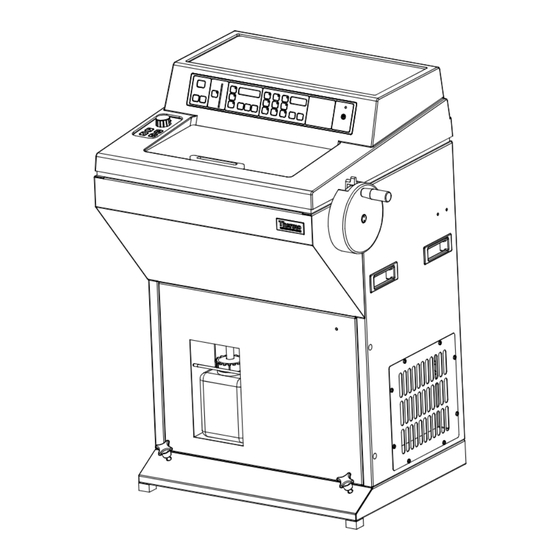
DESCRIPTION CRYOTOME OVERVIEw The Cryotome is designed for cutting frozen sections of fixed and unfixed specimens, rapidly and accurately, for future examination by microscope. It operates by rapidly freezing the sample in a temperature controlled environment, and provides means for sectioning the frozen sample by conventional microtome. -
Page 8: Controls
CONTROLS DESCRIPTION This chapter describes the displays and the functions of all the controls on the instrument. MAIN CONTROL PANEL The Main Control Panel is situated on the front of the instrument (a). Operation of the buttons is confirmed by an audible tone, a change in the display, or by an integral pushbutton indicator. - Page 9 2 The Micron Selector on the Standard Cryotome is a rotary knob which changes the thickness in 1µm steps between 1 and 30µm (see section 2.3.1) 2.2.2 SPECIMEN TRAVEL The ver tical bar graph contains separate segments that light up sequentially as the Specimen Head advances from its maximum available travel position.
- Page 10 2.2.3.1 TO SET ThE CLOCK Press and hold [CLOCK] and then press the relevant button detailed below. Release the buttons when the correct information is displayed. Press and hold [CLOCK] then press: To Set the... Display will show: [DAY] 1 - 7 Note Keep Monday as Day 1 to avoid confusion [hOURS]...
- Page 11 To start (PSAVE) mode immediately, press [IMMED DEfROST]. The instrument then runs its defrost cycle for 15 mins and goes to (PSAVE) on completion. Use [CANCEL DEfROST/ fUMIGATE] to end the function before the cycle is complete. Note: 1 It can take 1 - 2 hours after (PSAVE) mode to cool the Refrigerated Chamber sufficiently for use.
- Page 12 Defrosting stops after 15 minutes and the instrument reverts to its previous state. Press [CANCEL DEfROST/fUMIGATE] to stop the defrosting process earlier if required. Note 1 The compressor will not restart until 3 minutes after it stopped 2 Defrosting cannot take place if the Chamber or Cryobar temperature is above 0°C 3 If the Day 9 option is selected when setting the defrost times, then the instrument will enter STANDBY (PSAVE) mode when defrosting finishes.
- Page 13 vii the instrument rever ts to its previous setting when the fumigate cycle is finished. Note 1 If the Day 9 option is selected when the fumigation time is set, then the instrument enters Standby (PSAVE) mode when fumigation finishes. 2.2.4.3 [CANCEL DEfROST/fUMIGATE] Press [CANCEL DEfROST/fUMIGATE] to terminate a Defrost or Fumigate sequence.
- Page 14 2.2.5 TEMPERATURE CONTROLS CHAMBER CONTROLS TEMPERATURE °C To set the working temperature, the appropriate button must IMMED. CRYOBAR be pressed with [+] and [-] to raise or lower the value of LAMP DEFROST TEMP the number in the display. Press and hold until the desired IMMED.
- Page 15 One rotation of the knob equates to a movement of 100µm at the Specimen Head. 2.3.2 Cryotome E only The Advance Control Panel on the Cryotome E contains the following buttons that control movement of the Specimen Head; REWIND ADVANCE...
- Page 16 MESSAGE CODES The following displays show in the Temperature display when conditions are appropriate. CHAMBER CONTROLS TEMPERATURE °C IMMED. CRYOBAR LAMP DEFROST TEMP IMMED. CRYOBAR FUMIGATE BOOST CANCEL WINDOW WORKING DEFROST/ LOCK TEMP FUMIGATE Ald shows when fumigation is in progress. LOBAT signifies that the internal back-up battery is not charged sufficiently to retain information during an interruption of the mains supply.
- Page 17 Cryobar and Refrigerated Chamber are too warm Press [CLOCK] to clear. Err 4 denotes a window lock error (not locking or unlocking). Press [CLOCK] to clear. Note 1 Err 3 is not used on these versions of Cryotome. 77210163GB Issue 3...
- Page 18 CONNECTIONS The connections to the electronics box are shown below: WINDOW BOOST WINDOW BOOST Mains On/Off Circuit Breaker This is the main power switch of the instrument. Its use is fully described in section 3.5. Power Inlet The mains power inlet. It is fully described in section 3.4. window Boost Press the Window Boost switch to provide extra de-misting power in conditions of high humidity.
-
Page 19: Installation And Setting Up
Retrieve the accessories pack from on top of the pallet in front of the instrument, then lift the Cryotome off the Pallet. Make sure that you have received all the parts listed on the packing list supplied with the instrument. Contact your dealer if necessary Notes Inform your dealer immediately if there are any breakages or shortages. - Page 20 Always keep the instrument vertical to prevent damage to the wARNING refrigeration system. Consult your Thermo dealer if the Cryotome is to be moved to wARNING another building, or out of the area. Transit fixings must be re-fitted. The instrument must be kept upright at all times.
- Page 21 The rear panel must be removed to reach the transit fixings. To remove the rear panel, undo and remove the bolt from the centre of the rear panel. Undo the 8 screws that secure the rear panel, then carefully pivot the panel around its left hand side (as seen from the rear of the instrument).
- Page 22 (k). Replace the rear panel and 8 screws. Retain the transit plate for future use when moving the Cryotome. TO INSTALL ThE CRYOTOME Move the instrument to its permanent location. This must be level and provide a 300 mm (12”) clearance to the sides and rear of the instrument for ventilation.
- Page 23 Note 1 Inadequate ventilation may have an adverse effect on the cooling system. The recommended ambient temperature is 20°C (68°F); maximum = 35°C (95°F). Performance is adversely affected at ambient temperatures above 30°C (86°F). 2 Siting of the instrument on an uneven surface can have an adverse effect on the cooling system.
- Page 24 Slide the handwheel carefully onto the drive shaft at the top of the right hand side panel. The handwheel is supplied in the Accessory Pack. Make sure that the locating pin of the handwheel fits into the key-way of the drive shaft. The lever next to the handwheel handle is used to lock the handwheel to prevent inadvertent rotation.
- Page 25 REfER TO MATERIAL SAfETY DATA ShEET (MSDS) fOR fORMALIN KEEP SUffICIENT fORMALIN SOLUTION TO COVER ThE END Of ThE OUTLET TUBE IN ThE wASTE BOTTLE AT ALL TIMES TO PREVENT ThE RELEASE Of AEROSOLS OR CONTAMINANTS DURING USE. ELECTRICAL REQUIREMENTS Make sure that the voltage of the mains supply corresponds with the voltage rating on the rating plate on the back of the instrument.
- Page 26 ThE CRYOTOME MUST BE PROTECTIVELY EARThED. MAKE SURE ThAT ThE INSTRUMENT IS PLUGGED INTO A PROPERLY EARThED (GROUNDED) MAINS SUPPLY IT MUST BE POSSIBLE TO INTERRUPT ThE MAINS SUPPLY AT SOURCE BY REMOVING ThE PLUG fROM ThE MAINS SUPPLY SOCKET...
- Page 27 Press the O (OFF) side of the l / O switch inward to switch the instrument off. TO PREPARE ThE INSTRUMENT fOR USE Practice good biological safety procedures whenever the Cryotome is used. Make sure that the waste Bottle is filled with sufficient 10% formalin solution to cover the outlet pipe.
- Page 28 Aerosols can form when the specimen traverses the knife. These can be hazardous if inhaled. Setting up the Cryotome for routine operation involves the installation and adjustment of one or more of the following components of the microtome. Knife Holders...
- Page 29 A cam operated screw in the bottom of the knife base engages with a locating slot in the carrier. Pulling the pivoting lever toward you releases the assembly and enables it to be slid forward or backward on the Carrier. The setting determines the distance between the Knife Holder and the Specimen Head of the microtome.
- Page 30 Adjust the angle of the Knife Holder until the ‘0’ of the angle scale is approximately in line with the marker on the knife base, then push the right hand lever away from you to lock. Note The Knife Holder is adjusted to its precise operating angle later, after the blade or knife is installed 3.6.2 TO fIT A STANDARD SOLID KNIfE ThE KNIfE IS SUBSTANTIAL, EXTREMELY...
- Page 31 Carefully slide the knife in front of the removable knife guard and place it centrally and squarely in the base of the Knife Holder. Tighten the clamps clockwise to secure the knife in position 3.6.3 TO SET UP ThE KNIfE hOLDER AND ANTI-ROLL PLATE fOR STANDARD SOLID KNIVES Note These are the recommended settings.
- Page 32 Note To prevent the anti-roll plate heating up, make sure that it is kept close to the knife Use the two adjusting screws to set the anti-roll plate gap. Place a thin strip of paper between the knife/blade and the anti-roll plate.
- Page 33 3.6.4 TO fIT A DISPOSABLE BLADE Slide the Blade Transporter as far as possible to the right. ALwAYS USE MESh GLOVES TO AVOID INJURY whEN hANDLING DISPOSABLE BLADES. USE ThE DISPENSER whEN fITTING A NEw BLADE ALwAYS PLACE ThE PLASTIC KNIfE GUARD OVER ThE CENTRE Of PORTION Of ThE KNIfE whENEVER ThE INSTRUMENT IS NOT BEING USED fOR CUTTING...
- Page 34 USE ThE CORRECT BLADE TYPE fOR ThE BLADE hOLDER - EIThER LOw OR hIGh PROfILE 3.6.5 TO SET UP ThE KNIfE hOLDER AND ANTI- ROLL PLATE fOR DISPOSABLE BLADES Note These are the recommended settings. You may need further minor adjustments to obtain best results. Make sure that the top edge of the glass plate is parallel to the knife.
- Page 35 Ensure that there is a good edge i.e. there are no ‘nicks’ - on the anti roll plate. Use the brush supplied to keep the anti roll plate, the blade, and the clamp clean. ThE EDGES Of ThE GLASS ANTI-ROLL PLATE ARE ShARP Note To prevent the anti-roll plate heating up, make...
- Page 36 3.6.6.2 fine Orientation head Unscrew the shaft on the Quick Release Clamp to remove it. Screw the Quick Release Clamp onto the shaft in the centre of the Fine Orientation Head and turn the Orientation Clamp (c) on the right hand side of the Orientation Head away from you to secure the Clamp.
- Page 37 3.6.6.3 Coarse Orientation head Insert the shaft of the Quick Release Clamp into the hole in the centre of the Coarse Orientation Head. Turn the Orientation Clamp (d) on the left hand side of the Orientation Head to secure the Clamp. To adjust the up-to-down and left-to-right orientation of the specimen before sectioning takes place, first turn the knob (e) on the end of the adjustment shaft towards you to unlock the movement of the head.
-
Page 38: Operation
OPERATION INTRODUCTION When the instrument is not in use, lock the Handwheel and keep the instrument switched on, with the sliding window closed and locked, and the Refrigerated Chamber at approximately -15°C to -20°C. The Control Panel is disabled, and the instrument is inoperable, when the keyswitch is vertical. - Page 39 Chamber temperature to the required temperature. There are several methods of embedding a specimen for work on a cryotome. The following instructions describe one suggested method. Take a clean Cryocassette that has been held at room temperature. Apply a layer of ™...
- Page 40 TO AVOID ThE POSSIBILITY Of CROSS CONTAMINATION: 1 MAKE SURE ThAT ThE PELTIER PLATfORM Of ThE CRYOBAR IS COLD ENOUGh 2 DO NOT USE TOO MUCh PRESSURE whEN APPLYING ThE hEATSINK. 3 MAKE SURE ThE CRYOCASSETTES AND hEAT SINKS ARE CLEAN BEfORE USE Notes Do not use too much mountant or get it onto the sides or back of the...
- Page 41 [E only]: Alternatively, if sufficient ‘Travel Available’ is indicated on the Specimen Travel Indicator, advance the specimen towards the knife using the double chevron (coarse), then the single chevron (fine), push-buttons of the miniature control panel on the left hand side. If necessary use the Rotary Control to obtain fine positioning of the specimen with respect to the knife.
- Page 42 If the specimen is to be stored frozen, wrap it in metal foil before putting it into a freezer. Do not store it in the Refrigerated Chamber of the Cryotome. If the specimen is to be fixed, allow it to thaw before placing it in a suitable fixative;...
-
Page 43: Cleaning And Maintenance
CLEANING AND MAINTENANCE GENERAL It is important that decontamination and cleaning of the instrument becomes an automatic routine - especially if the source of material is unknown. It is recommended that a log is kept which lists: Material Cut. Degree of Risk. Decontamination Performed. - Page 44 INSIDE ThE UNIT. DO NOT REMOVE ANY ACCESS COVERS Always wear protective gloves when you clean or decontaminate the wARNING Cryotome to protect yourself against the effects of chemicals Do not use any chemicals that may interact with materials of wARNING manufacture.
- Page 45 Note For safety, the fumigation cycle cannot take place if the window is not closed and locked. If the Cryotome is not refrozen after fumigation has taken place, wARNING formaldehyde fumes will be present in the chamber. Take care when opening the window.
- Page 46 The high polish finish inside the Refrigerated Chamber is designed to minimise the adhesion of particles to the side walls. Do not use scouring powder or harsh detergents or you will degrade wARNING the polished finish 5.3.1 TO CLEAN ThE KNIfE hOLDER Remove the knife or blade before cleaning Knife holder wARNING It is important to keep the Knife Holder clean.
- Page 47 Note It is not necessary to use formalin during the Defrost/Fumigate cycle The waste bottle collects water from the cooling coils of the heat exchanger. It also collects debris when the Refrigerated Chamber is washed down so the contents must be disposed of in an appropriate manner. ALwAYS KEEP AT LEAST 200ml Of 10% fORMALIN SOLUTION OR SIMILAR DE-CONTAMINANT IN ThE wASTE BOTTLE.
- Page 48 Tighten the two screws that hold the shade, and replace the top cover. ELECTRICAL PROTECTION The mains input supply feeds the Cryotome via a trip device that interrupts the electrical supply to the instrument if an internal fault occurs. The trip replaces the function of a fuse.
- Page 49 ELECTRICAL PROTECTION IS INCLUDED TO PROTECT ThE OPERATOR AND ThE INSTRUMENT. DO NOT ATTEMPT TO OVERRIDE ThE PROTECTION TRIP Portable Appliance Testing (PAT) should only be carried out annually to wARNING avoid damaging the equipment flash testing should only be carried out when absolutely necessary as wARNING damage to sensitive electronic devices may occur 77210163GB Issue 3...
-
Page 50: Trouble Shooting
Thermo Service Contract is used to ensure future reliability, and consistency of performance. Cryotome has self test routines built in so that fault codes (f:(Number)) show in the displays if malfunctions occur. No operator response is involved following a fault code other than to contact your Thermo Engineer for service. - Page 51 TABLE 2 PROBLEMS - whEN SECTIONING SYMPTOMS POSSIBLE CAUSE REMEDY Specimen cracks as it is 1 Too rapid freezing 1 Cut specimen into thinner frozen 2 Specimen too thick block. Specimen falls off 1 Specimen too thick. 1 Cut specimen into thinner Cryocassette.
- Page 52 TABLE 2 (continued) PROBLEMS - whEN SECTIONING Sections show ice 1 Specimen not frozen 1 Allow Cryoboost longer artifacts. quickly enough. time before adding mountant and admitting 2 Specimen too thick. specimen. 2 Cut thinner. Sections show signs of 1 Knife not supported 1 Disposable knives are most the effects of vibration.
- Page 53 TABLE 3 ERROR MESSAGES SYMPTOMS POSSIBLE CAUSE REMEDY LOBAT 1 Internal back-up battery is losing 1 Switch on/leave the unit charge switched on. 2 Have the battery replaced. Err 1 1 Invalid pushbutton entry. 1 Use the correct 2 Too many pushbuttons pressed pushbutton.
-
Page 54: Specification And Accessories
SPECIfICATION AND ACCESSORIES SPECIfICATION 7.1.1 Physical Width 660 mm (26 ins) Depth 640 mm (25¼ ins) Height 1070 mm (42¼ ins) Weight 120 kg (265 lbs) Mounting 4 off movable castors, (front 2 retractable) 7.1.2 Electrical pply Voltages: 220 - 240 V a.c. (~); 50/60 Hz; 1700VA Power Su 110 - 120 V a.c. - Page 55 Altitude up to 2000m (6,500 feet) Pollution degree r voltage category 7.1.7 Thermo part numbers Standard Cryotome 220 - 240 V; 50/60 Hz (English) 0620 220 - 240 V; 50/60 Hz (German) 0620/G 220 - 240 V; 50/60 Hz (French) 0620/F 110 - 120 V;...
- Page 56 ACCESSORIES INSTRUMENT ACCESSORIES QUANTITY PART NUMBER Solid Knife Holder with Anti Roll Plate 0620-023 High Profile Disposable Blade Holder with Anti Roll Plate 0620-021H Low Profile Disposable Blade Holder with Anti Roll Plate 0620-021L Orientation Heads: Fine Orientation Head 0620-006 Coarse Orientation Head 0620-008 Cryocassettes...
-
Page 57: Warranty Statement
wARRANTY STATEMENT We are proud of our quality and reliability, and of our after-sales service. We continuously strive to improve our service to our customers. Please ask your distributor or representative about Service Contracts which can keep your purchase in peak condition for many years to come. Warranty provisions necessarily vary to comply with differences in national and regional legislation, and you can find details in your delivery documents or from your dealer or representative. - Page 58 Manufacturer’s Address: Tudor Road, Manor Park, Runcorn, Cheshire, WA7 1TA ENGLAND Product Description: Electronic Cryostat Product Designation: Cryotome ® (0620E, 0620E/G, 0620E/F, 0620E/110) including accessories supplied as standard, and the following accessories: Orientation Heads: 0620-006, 0620-008 Cryocassettes: 603, 605, 77210080, 0620-001, 0620-007,...
- Page 59 Manufacturer’s Address: Tudor Road, Manor Park, Runcorn, Cheshire, WA7 1TA ENGLAND Product Description: Standard Cryostat Product Designation: Cryotome ® (0620E, 0620/G, 0620/F, 0620/110) including accessories supplied as standard, and the following accessories: Orientation Heads: 0620-006, 0620-008 Cryocassettes: 603, 605, 77210080, 0620-001, 0620-007,...
-
Page 60: Appendix A - Transportation Instructions
APPENDIX A TRANSPORTATION INSTRUCTIONS INTRODUCTION d to transport the Cryotome, follow these packaging instructions. If you ever nee TO REPACK ThE CRYOTOME E ThE CRYOTOME E wEIGhS APPROXIMATELY 120kg (265lbs). ALwAYS GET hELP TO SAfELY MOVE ThE INSTRUMENT wIThOUT RISK Of INJURY... - Page 61 Empty the waste bottle and replace the empty bottle. BE AwARE Of POTENTIAL BIOhAZARDS AND fORMALIN CONTAINED IN ThE wASTE BOTTLE. DISPOSE Of CORRECTLY IN ACCORDANCE wITh LOCAL PROCEDURES Lock the handwheel and remove the handwheel bolt. Remove the handwheel Secure the Cryobar with a rubber band.
- Page 62 10 Fit the transit plate to the rear of the microtome assembly. 11 Place the spacer between the microtome casting and leadscrew arm (ii). Carefully adjust the leadscrew so that the leadscrew arm rests on the spacer (i). (Note that the leadscrew may need to be manually turned). Fit the stud from underneath the leadscrew and secure the top spacer with the ‘butterfly’...
- Page 63 TO REPACK ThE STANDARD CRYOTOME ThE STANDARD CRYOTOME wEIGhS A P P R OX I M AT E LY 1 2 0 k g ( 2 6 5 l b s ) . PRODUCT RETURN SAFETY DECLARATION Part 1 DECONTAMINATION CERTIFICATE...
- Page 64 Lock the handwheel and remove the handwheel bolt. Remove the handwheel Use the Advance Panel to move the Specimen Head backwards. Secure the Cryobar with a rubber band. Lift the top cover and secure the window in the closed position using sticky tape. Turn the instrument lowering knobs counter-clockwise to lower the castors to the ground.
- Page 65 11 Fit the transit plate to the rear of the microtome assembly. 12 Unscrew and remove the nut on top of the defrost valve. Carefully remove the defrost valve from the copper tube and use cable ties to secure it to the transit plate on the rear of the microtome.
- Page 66 PRODUCT RETURN SAfETY DECLARATION Part 1 DECONTAMINATION CERTIfICATE Any instrument or part of any instrument must be clean before being returned, and where necessary accompanied by a completed Decontamination Certificate. Should the instrument or any part of it be received in an unclean condition, or Thermo Fisher Scientific consider it to be a hazard, the instrument or part will be returned unrepaired at the expense of the customer.
-
Page 67: Appendix Bapproved Reagent List
APPENDIX B APPROVED REAGENT LIST INTRODUCTION This Section lists all the reagents that Thermo specify can be used with the Cryotome cryostat. If you want to use a reagent not included in this list, contact your Thermo agent for advice. -
Page 68: Appendix Cexamples
INTRODUCTION This section provides a guideline cutting temperatures for the Thermo Cryotome. S U G G E S T E D C U T T I N G T E M P E R AT U R E S f O R fROZEN TISSUES BE AwARE ThAT TISSUE SAMPLES MAY POSE A BIOhAZARD. - Page 69 CONTENTS 3 Symbols CONTROLS 8 --- Message Code 16 Advance Control Panel 15 ] BioHazard symbol 2 Cryotome E 15 ] Harmful chemical symbol 2 Standard Cryotome 15 ] Temperature symbol 1 2 Connections 18 ] Warning symbol 2 Mains On/Off Circuit Breaker 18...
- Page 70 To Switch On 26 Decontamination Warnings 5, 43 To Unpack 19 dEf Message Code 16 DESCRIPTION 7 Cryotome SME Annotated Diagram 7 LOBAT Message Code 16 Cryotome SME Overview 7 Mains On/Off Circuit Breaker 18 Electrical Earthing Requirements 5, 26...
- Page 71 Electrical 54 Environment 55 Fuses 54 Microtome 55 Physical 54 Power Demand Characteristics 54 Switch Convention 54 Thermo Part Numbers 55 Statement of intended use 4 TRANSIT FIXINGS 20 Microtome Transit Fixings 22 Refrigeration Transit Fixings 21 TROUBLE SHOOTING 50 General 50 Table 1 - Instrument Function 50 Table 2 - Problems when sectioning 51–52...
- Page 72 77210163GB Issue 3...
Need help?
Do you have a question about the Cryotome and is the answer not in the manual?
Questions and answers