Table of Contents
Advertisement
Quick Links
™
CTS
Xenon
USER GUIDE
For electroporation of primary and stem cells for cell therapy
development and manufacturing
Catalog Number A52727
Publication Number MAN0025488
Revision A.0
For Research Use or Manufacturing of Cell, Gene, or Tissue- Based
Products. CAUTION: Not intended for direct administration into
humans or animals.
™
Electroporation System
Advertisement
Table of Contents

Related Manuals for Thermo Scientific CTS Xenon


Summary of Contents for Thermo Scientific CTS Xenon
- Page 1 ™ ™ Xenon Electroporation System USER GUIDE For electroporation of primary and stem cells for cell therapy development and manufacturing Catalog Number A52727 Publication Number MAN0025488 Revision A.0 For Research Use or Manufacturing of Cell, Gene, or Tissue- Based Products. CAUTION: Not intended for direct administration into humans or animals.
- Page 2 Life Technologies Holdings Pte Ltd | Block 33 | Marsiling Industrial Estate Road 3 | #07-06, Singapore 739256 For descriptions of symbols on product labels or product documents, go to thermofisher.com/symbols-definition. The information in this guide is subject to change without notice. DISCLAIMER: TO THE EXTENT ALLOWED BY LAW, THERMO FISHER SCIENTIFIC INC.
-
Page 3: Table Of Contents
Contents ■ CHAPTER 1 Product information ..........6 Product description . - Page 4 Contents ■ CHAPTER 2 Methods ............. 29 Electroporation protocol options .
- Page 5 Contents ■ APPENDIX C Recommended instrument settings ......60 About Instrument ............. . 60 Recommended instrument settings .
-
Page 6: Chapter 1 Product Information
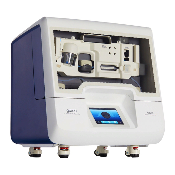
Product information Product description ™ ™ ™ ™ The CTS Xenon Electroporation System is a novel, benchtop device consisting of the CTS Xenon Electroporation Instrument, single-use consumables for performing transfection of cells, and specialized buffers. ™ ™ The CTS Xenon Electroporation Instrument efficiently delivers gene editing payloads (DNA, RNA and proteins) into all mammalian cell types including primary and stem cells with a high cell survival rate. -
Page 7: Product Contents
Chapter 1 Product information Product contents Product contents ™ ™ Xenon system contents ™ ™ The contents of the CTS Xenon Electroporation System are listed in the following table. The system is shipped at room temperature. ™ ™ page 8 for specifications and description of the CTS Xenon Electroporation Instrument, and... -
Page 8: System Components
Chapter 1 Product information System components System components ™ ™ Xenon Electroporation Instrument Front and rear view Door Castor with pad and wheel (× 4) Touch screen Grab rail (on left and right sides) USB wireless adaptor port Fuse compartment USB 2.0 port Ethernet port Power switch... - Page 9 Chapter 1 Product information System components Internal view Input bag hook Cooling block Cartridge handle springboard Chip reader Stopcock driver Upper electrode mount Input pump Electroporation chamber holder Ultrasonic sensor Output pump Mixing cup interface Output bag tray Mixing cup output pump ™...
-
Page 10: Singleshot Electroporation Chamber
Chapter 1 Product information System components SingleShot electroporation chamber Top adaptor with authentication chip Electroporation chamber Upper electrode housing Lower electrode Upper electrode ™ Xenon ™ Electroporation System User Guide... -
Page 11: Multishot Electroporation Cartridge
Chapter 1 Product information System components MultiShot electroporation cartridge Front Luer port for output bag Electroporation chamber Cartridge handle (on left and right sides) Electroporation chamber push latch Mixing cup (25 mL capacity) Luer port for input bag Rear Mixing cup Sterile filters Electroporation chamber Electrode... -
Page 12: Xenon ™ Buffer Kits
Chapter 1 Product information Upon receiving the instrument Xenon ™ buffer kits ™ ™ There are two cell resuspension buffers available for use with the CTS Xenon Electroporation System. ™ ™ • The CTS Xenon Electroporation Buffer is designed for use with various primary cell types when performing electroporation with standard DNA or RNA based payloads for gene expression or gene knockdown based applications. -
Page 13: Required Materials Not Provided
Chapter 1 Product information Upon receiving the instrument WARNING! Do not place the instrument adjacent to, or stack with other equipment to avoid improper operation. If this type of placement is necessary, all the instruments and equipment should be observed to ensure that they operate normally. WARNING! Use of accessories, transducers, and cables other than those specified or provided by the manufacturer of the equipment can result in increased electromagnetic emissions, or decreased electromagnetic immunity of this equipment, and result in improper operation. -
Page 14: User Interface Overview
Chapter 1 Product information Upon receiving the instrument User interface overview Symbol Function Main dial Load protocol Displays the instrument status when a protocol is run (see “Touchscreen status indicators”) Optimization screen Perform optimization for a new protocol (see “Optimization protocol” on page 59 for more details) -
Page 15: Touchscreen Controls
Chapter 1 Product information Upon receiving the instrument Touchscreen controls Table 1 General touchscreen controls Button Function Returns to the previous screen Go to Home screen Go to Sign in screen Go to Settings screen Close the current modal window. Touchscreen status indicators Table 2 Status indicators Button... - Page 16 Chapter 1 Product information Upon receiving the instrument Enter text When you press a field that requires the input of text, the text editor, as seen in the following figure, opens. Enter a letter Delete Change letter case Close and save Enter punctuation or other symbols Close without saving Enter numbers...
-
Page 17: First Time Instrument Setup
Chapter 1 Product information First time instrument setup First time instrument setup 1. Place the instrument in a protected location with at least 10 cm of free space around the perimeter for ventilation. 2. Connect the power supply cable to the power inlet. The instrument operates at voltages of 100–240 VAC and the frequency range of 50/60 Hz. - Page 18 Chapter 1 Product information First time instrument setup 3. Once a wireless connection has been detected, a list of the available networks is displayed. Select the network name of your choice or select Join others. Note: If you choose Join others, the Configure and Join Network screen opens. 4.
- Page 19 Chapter 1 Product information First time instrument setup Set up a wired connection Connect one end of a Ethernet cable to the instrument Ethernet port, and the other end to an Ethernet port wall plug (see page 8 for port location). 1.
- Page 20 Chapter 1 Product information First time instrument setup 3. In the Instrument Settings screen, select Network configuration. 4. In the Network Connection screen, select a field in the Wired panel. Wireless panel Wired panel 5. Select a method to enter an IP address. a.
-
Page 21: Create A User Profile On The Instrument
Chapter 1 Product information First time instrument setup b. Select Static IP to enter an IP address manually, then enter the appropriate IP addresses for the instrument, the Subnet Mask, and, optionally, the Default Gateway, the Primary DNS Server, and the Secondary DNS Server using the numeric editor. Addresses are in the form of X.X.X.X, where each X is a 3- digit number, from 001 to 255. -
Page 22: Manage User Profiles
Chapter 1 Product information First time instrument setup Manage user profiles All users can manage their profiles to edit personal folder names, change PINs, and link to the cloud by selecting their (Profile) to enter their My Profile page. Users with Administrator profiles (as indicated by an asterisk after their user name) also have the ability to manage all user accounts by selecting All accounts after entering their My Profile page. -
Page 23: About The Thermo Fisher ™ Connect Platform
Chapter 1 Product information About the Thermo Fisher ™ Connect Platform An asterisk appears next to user profiles with administrator privileges. ™ About the Thermo Fisher Connect Platform ™ ™ ™ The Thermo Fisher Connect Platform enables access to the CTS Xenon Electroporation Instrument through InstrumentConnect by way of a web browser or mobile device. -
Page 24: Link The Instrument To Connect (Administrator Only)
Chapter 1 Product information About the Thermo Fisher ™ Connect Platform Link the instrument to Connect (Administrator only) 1. Select (Sign In)4Link cloud, then select the cloud region of the instrument. 2. Select the method for linking the instrument to Connect . Connect by mobile device Select (Sign In)4Get started4Connect4Mobile device from the instrument to generate a QR... - Page 25 Chapter 1 Product information About the Thermo Fisher ™ Connect Platform 2. Launch the Instrument Connect Mobile Application and log in using your Connect login and password. 3. Capture the QR code on the instrument screen. Connect by PC Select (Sign In)4Get started4Connect4PC from the instrument to generate a linking code.
-
Page 26: Connect The Instrument To The Internet
Chapter 1 Product information About the Thermo Fisher ™ Connect Platform Connect the instrument to the Internet 1. Connect your instrument to the Internet. • Connect through the instrument Ethernet port using a cable. • Connect via wireless connection with a USB-enabled Wi-Fi dongle. 2. -
Page 27: Add An Instrument To Your Connect Account
Chapter 1 Product information About the Thermo Fisher ™ Connect Platform Add an instrument to your Connect account ™ ™ Connect supports access to the CTS Xenon instrument with the InstrumentConnect application on your mobile device or from a web browser. When the instrument is connected, real-time instrument status can be viewed from the InstrumentConnect application. - Page 28 Chapter 1 Product information About the Thermo Fisher ™ Connect Platform Access your Connect account from an instrument 1. Swipe down to open the Notifications screen. 2. Select Sign in. Note: If another user account is displayed, select the username to sign out and connect a different user account.
-
Page 29: Chapter 2 Methods
Methods Electroporation protocol options There are three options available for selecting an electroporation protocol: • If a protocol with the necessary electroporation parameters for your cell type already exists, the protocol can be chosen from a list of User created or Template protocols by selecting Load protocol on the main dial. -
Page 30: Create/Edit Singleshot Protocols
Chapter 2 Methods Create/Edit SingleShot protocols The individual parameters (voltage, pulse width, pulse number, pulse interval) have their own independent upper limits. However, certain combinations of these variables will exceed the energy limit of the system even when still within the individual limit. For example, a protocol of 2300 V/30 ms/3- pulses can be entered but not run as it exceeds the energy limit of the system despite each variable being within its limits. -
Page 31: Edit Singleshot Protocol
Chapter 2 Methods Create/Edit SingleShot protocols 3. Select a text field or open a dropdown menu to set the electroporation parameters for the protocol. Note: Swipe the screen to scroll up or down. 4. Select Save (see “Save a Protocol” on page 35), Next to run the protocol, or Cancel. - Page 32 Chapter 2 Methods Create/Edit SingleShot protocols 3. Select a text field or open a dropdown menu to set the electroporation parameters for the protocol. Note: Swipe the screen to scroll up or down. 4. Select Save as to save the edited protocol (see “Save a Protocol” on page 35).
-
Page 33: Create/Edit Multishot Protocols
Chapter 2 Methods Create/Edit MultiShot protocols Create/Edit MultiShot protocols MultiShot protocols are used to process 1 × 10 to 2.5 × 10 cells in a 5–25 mL sample volume. Create MultiShot Protocol 1. In the Home screen, select Create protocol. 2. -
Page 34: Edit Multishot Protocol
Chapter 2 Methods Create/Edit MultiShot protocols Edit MultiShot Protocol 1. In the Home screen, select Create protocol. 2. Select MultiShot4 Open existing. 3. Select a text field or open a dropdown menu to set the electroporation parameters for the protocol. Note: Swipe the screen to scroll up or down. -
Page 35: Save A Protocol
Chapter 2 Methods Save a Protocol Save a Protocol 1. Once edits to a protocol are complete, select Save to save the protocol. 2. In the Save screen, enter a name for the edited protocol. Characters allowed Characters not allowed <100 characters >100 characters Letters, numbers, spaces, underscores, and... -
Page 36: General Guidelines
Chapter 2 Methods General guidelines General guidelines • To obtain the highest transfection efficiency optimize transfection conditions by using the pre- programmed optimization protocols (see “Optimization protocol” on page 59). • Because cell culture conditions vary from user to user, be sure to use low passage number, actively dividing cells (for dividing cells). -
Page 37: Controls
Chapter 2 Methods Required materials Controls High-quality controls play an integral role in the successful optimization of gene editing conditions in your cell type of choice. To assess transfection efficiency for your cell type, it is recommended to ™ use a plasmid encoding GFP (green fluorescent protein) or any colored variant of GFP (Clontech equivalent). -
Page 38: Prepare Cells
Chapter 2 Methods Prepare cells Prepare cells Prepare cell suspensions for electroporation either manually, or using an automated system such as the ™ ™ Rotea Counterflow Centrifugation System. A protocol for preparation of activated T cells is provided as an example of preparation of cells for electroporation, but conditions will vary depending upon cell type and the downstream experimental procedure to be performed. - Page 39 Chapter 2 Methods Prepare cells 5. If cells are grown in static flasks, gently mix the cells with a serological pipette to dislodge the cells from the magnetic beads. 6. Transfer the cells and beads into an appropriate vessel for removal of magetic beads with either ™...
-
Page 40: Perform Electroporation
Chapter 2 Methods Perform electroporation Perform electroporation Run SingleShot protocol SingleShot protocols are used to process 2 × 10 to 1 × 10 cells in a 1 mL sample volume. To avoid contamination, prepare the SingleShot Chamber in a cell culture hood using sterile procedure. Load a SingleShot Protocol 1. - Page 41 Chapter 2 Methods Perform electroporation Prepare SingleShot chamber 1. Fill the SingleShot chamber with ~1 mL of cell suspension using a P1000 micropipette. Place the tip of the pipette at the bottom of the chamber and fill from the bottom up to avoid bubble formation.
-
Page 42: Run Multishot Protocol
Chapter 2 Methods Perform electroporation Run MultiShot protocol MultiShot protocols are used to process 1 × 10 to 2.5 × 10 cells in a 5–25 mL sample volume. To avoid contamination, bring all of the required consumables to a cell culture hood to prepare the MultiShot cartridge using sterile procedure. - Page 43 Chapter 2 Methods Perform electroporation 6. Attach the input bag to the holder hook and make sure the tubes are secure. 7. Place the output bag in the output bag tray and make sure the tube is secure. Note: The tube leading to the output bag should be positioned so that it faces the opening of the instrument to minimize bubble formation.
- Page 44 Chapter 2 Methods Perform electroporation 8. Route the tube that runs from the input bag to the mixing cup through the input pump and ultrasonic sensor, then close the pump. Note: Since the path of the tubing is not visible once the cartridge is locked in place, the tube that runs to the mixing cup is identifiable by the tag marked "input"...
- Page 45 Chapter 2 Methods Perform electroporation 10. Route the tubing from the input bag into the mixer pump, then close the pump. 11. Route the tubing from the mixer pump across the entire length of the pre-cooling block. 12. Release the pinch clamps on the input and output bags. Note: Ensure that the tubes are not crimped to allow unimpeded flow of liquid.
-
Page 46: Post-Electroporation Procedure
Chapter 2 Methods Perform electroporation Run MultiShot Protocol 1. Enter the MultiShot volume, then select Next. 2. Select Transfer to move cells from the input bag to the mixer. 3. Close the instument door. 4. Select Electroporate to start the electroporation process. Post-electroporation procedure After electroporation is complete, secure the pinch clamps on the output bag to prevent loss of the sample. -
Page 47: Maintenance
Chapter 2 Methods Maintenance Maintenance Cleaning and maintenance CAUTION! Cleaning and decontamination. Use only the cleaning and decontamination methods specified in the user documentation. It is the responsibility of the operator (or other responsible person) to ensure the following requirements are met: ·... -
Page 48: Replace The Fuses
Chapter 2 Methods Maintenance Replace the fuses Required materials • Two UL Listed fuse, rated 10 A, Time-Lag T, 250 VAC, size: 5 × 20 mm • Fine flat-tip screwdriver Replace fuses DANGER! ELECTRICAL SHOCK HAZARD. Severe electrical shock, which could cause physical injury or death, can result from working on an instrument when the high voltage power supply is operating. - Page 49 Chapter 2 Methods Maintenance Determine firmware version on instrument When a new firmware version is released, you may be required to load the new firmware on the instrument. You will need a USB memory device and, if your instrument requires login, the login details to upgrade the firmware.
- Page 50 Chapter 2 Methods Maintenance Upgrade the instrument firmware (USB drive) IMPORTANT! You cannot upgrade the firmware while a run is in progress. 1. Insert the USB memory device with the new firmware in the USB port of your instrument. Note: For instruments with the USB shortcuts feature enabled, you will be directed to the USB shortcuts screen.
-
Page 51: Self Verification Test
Chapter 2 Methods Maintenance Self Verification test Use the Self Verification Test feature to check the instrument hardware. The check includes testing the cooling block, pumps, and other components. Select Last Test to view the results of the last Self Verification Test. Carry out the Self Verification Test periodically or whenever there is an intermittent instrument error. -
Page 52: Repackaging The Instrument
Chapter 2 Methods Maintenance Repackaging the instrument If you need to send the instrument to Thermo Fisher Scientific for warranty issues, or you wish to transport the instrument to another location, repackage the unit as follows. Note: Prior to sending the instrument, ensure the instrument is properly decontaminated if the instrument is exposed to any viable biological agents, radioactive materials, or hazardous chemicals (toxic, carcinogenic, mutagenic, toxic for reproduction, sensitizing, and/or have not been fully tested). -
Page 53: Appendix A Troubleshooting
Troubleshooting Troubleshooting Problem Cause Solution No power (the display remains AC power cord is not connected Check AC power cord blank when the power is turned connections at both ends. Use the correct cords. Consumable error Authenticator chip missing or Check if the authenticator chip detection failure is in the consumable. - Page 54 Appendix A Troubleshooting Troubleshooting (continued) Problem Cause Solution Arcing (sparks) Air bubbles in the electroporation Check to see if there are bubbles chamber in the SingleShot Chamber.. Perform a self-diagnostics test if the error is persistent. Contact field service if the error is persistent.
-
Page 55: Remove Jammed Electroporation Chamber
Appendix A Troubleshooting Remove jammed electroporation chamber (continued) Problem Cause Solution Low transfection efficiency Mycoplasma contaminated cells Test cells for Mycoplasma contamination. Start a new culture from a fresh stock. Non-reproducible transfection Inconsistent cell confluency or Always use cells with low passage efficiency passage number number and harvest cells with... - Page 56 Appendix A Troubleshooting Remove jammed electroporation chamber 2. Twist the knurled knob clockwise until the pin rests in the vertical slot to release the top electrode holder. 3. Remove the electroporation chamber. 4. Twist the knurled knob counter-clockwise and ensure that the pin is fully engaged in the horizontal slot of the knob.
-
Page 57: Error Codes
Appendix A Troubleshooting Error codes Error codes This section describes the error messages displayed by the instrument. Contact Technical Support if the instrument needs to be sent for servicing. Error code Meaning 0x8851 Subsystem firmware corrupted. Please update firmware. 0x8852 Subsystem firmware version mismatch. - Page 58 Appendix A Troubleshooting Error codes (continued) Error code Meaning 0x1601 Extractor pump lid is not closed. 0x1701 Filler pump lid is not closed. 0x0101 Unable to move capper to home position 0x0102 Unable to move capper to uncap position. 0x0200 Unable to start draining.
-
Page 59: Appendix B Optimization
Optimization Optimization protocol Electroporation is mainly dependent on the combination of three electric parameters such as the electric field, pulse width, pulse interval, and pulse number. Based on your initial results, you may need to optimize the electroporation parameters for your cell type and payload. The process involves applying electrical energy to cells to achieve temporary pores that allow for the transfer of genetic material across the cell membrane. -
Page 60: Appendix C Recommended Instrument Settings
Recommended instrument settings About Instrument Select Settings4About Instrument to find out more information about the instrument (e.g., firmware version and instrument statistics). • Select EULA to view the End User License Agreement, or download it to a USB drive. • Select Check updates to find out if updates are available for the instrument . Recommended instrument settings Select (Settings) and access the Settings screen to configure the instrument. -
Page 61: Instrument Settings (Administrator Only)
Appendix C Recommended instrument settings Recommended instrument settings Instrument settings (Administrator only) Select Instrument Settings to set the following instrument parameters. • Instrument name Select the Instrument name field to activate the text editor. Enter up to 25 alphanumeric characters to identify the instrument. Note: The instrument name cannot have spaces. - Page 62 Appendix C Recommended instrument settings Recommended instrument settings • Sleep mode Use the Off and On toggle to disable or enable sleep mode. In the 'On' mode, select the Edit Time field to activate the numeric editor to set the time after which the instrument will go from idle mode to standby mode.
- Page 63 Appendix C Recommended instrument settings Recommended instrument settings • Brightness Use the slider to adjust the brightness of the touch screen. • Cooling block temperature Select the Edit temperature field to activate the number pad. Enter the desired value, then select Done.
- Page 64 Appendix C Recommended instrument settings Recommended instrument settings Wireless panel Wired panel • Cloud region (Administrator profile only) Select the appropriate field to set the cloud region for the instrument. • Auto sign out (Administrator profile only) Use the toggle to enable/disable automatic sign out of a user when no activity is detected on the instrument for a selected period of time.
-
Page 65: Maintenance & Services
Appendix C Recommended instrument settings Maintenance & services Maintenance & services Select Maintenance & Services to set the following instrument parameters. • (Administrator only) Select Software Update to update the System firmware. See “Upgrade the system firmware” on page 48 for instructions on updating the firmware. -
Page 66: Run History
Appendix C Recommended instrument settings Run History Run History Select Run History to display the entire list of runs performed by the instrument. • Select a particular file to view the details of that run. • Select Export to save the run details to a USB memory device, or Delete to delete the the run history file. - Page 67 Appendix C Recommended instrument settings Run History – Delete a run report – Select all run reports – Export a run report ™ Xenon ™ Electroporation System User Guide...
-
Page 68: Appendix D Specifications
Specifications Product specifications Electrical rating 100–240 ±10% VAC, 1200 VA Electroporation pulse voltage range 500–2500 V Electroporation pulse width range 1–30 ms Electroporation pulse interval range 500–1000 ms Number of electroporation pulses 1–10 pulses Cell mixer stirrer rotating speed 60 rpm Pre-cooling technology Peltier Pre-cooling temperature setting range... -
Page 69: Appendix E Related Products
Related products Accessory products Additional products ™ The following products are for use with the Xenon Electroporation System and are available separately. For more information, go to thermofisher.com or contact Technical Support. Product Quantity Catalog no. ™ ™ Dynabeads CD3/CD28 10 mL 40203D ™... - Page 70 Appendix E Related products Accessory products (continued) Product Quantity Catalog no. ™ TrueCut Cas9 Protein 2.5 µg A45220P ™ TrueTag Donor DNA Kit, GFP 10 reactions A42992 TrueTag ™ Donor DNA Kit, RFP 10 reactions A42993 ™ Xenon ™ Electroporation System User Guide...
-
Page 71: Appendix F Safety
Safety Safety information ™ ™ Follow the instructions in this section to ensure safe operation of the CTS Xenon Electroporation ™ ™ Instrument. The CTS Xenon Electroporation System is designed to meet EN61010-1 Safety ™ ™ Standards. To ensure safe, reliable operation, always operate the CTS Xenon Electroporation Instrument according to the instructions in this manual. -
Page 72: Safety Compliance
Appendix F Safety Safety compliance Safety compliance The instrument design and manufacture complies with the following standards and requirements for safety, electromagnetic compatibility, and Environmental WEEE. Reference Description EU Directive 2014/35/EU European Union “Low Voltage Directive” IEC 61010-1 Safety requirements for electrical equipment for measurement, control, and laboratory use –... -
Page 73: Symboles D'information
Appendix F Safety Symboles d’information (continued) Symbol and description This product conforms to UL 61010-1, CAN/CSA C22.2 No.61010-1 “Safety Requirements for Electrical Equipment for Measurement, Control, and Laboratory Use, Part l: General Requirements.” Instruments bearing the UL symbol are certified by Underwriters Laboratories to be in conformance with the applicable safety standard for the US and Canada. -
Page 74: Environmental Requirements
Appendix F Safety Environmental requirements (continued) Symbol and description Ce produit est conforme à UL 61010-1, CAN/CSA C22.2 No.61010-1 «Exigences de sécurité pour l’équipement électrique pour la mesure, le contrôle et l’utilisation en laboratoire, Partie l : Généralité Les exigences.» Les instruments portant le symbole UL sont certifiés par Underwriters Laboratories conforme à... -
Page 75: Electromagnetic Compatibility (Emc) Standards
Appendix F Safety Electromagnetic compatibility (EMC) standards Electromagnetic compatibility (EMC) standards Class A notice This equipment has been tested and found to comply with the limits for a Class A digital device, pursuant to part 15 of the FCC Rules; and CISPR 11 Class A. These limits are designed to provide reasonable protection against harmful interference when the equipment is operated in a commercial environment. -
Page 76: Electrical Safety
Appendix F Safety Electrical safety (continued) Reference Description IEC 61326-1 Class A Electrical Equipment for Measurement, Control and Laboratory Use – EMC Requirements – Part 1: EN 61326-1 Class A General Requirements The equipment is intended for use in a basic electromagnetic environment. -
Page 77: Chemical Safety
Appendix F Safety Chemical safety • Use suitable overvoltage protection to ensure that no overvoltage (such as that caused by a bolt of lightning) can reach the product. Otherwise, the person operating the product will be exposed to the danger of an electric shock. •... -
Page 78: Biological Hazard Safety
Appendix F Safety Biological hazard safety Biological hazard safety WARNING! Potential Biohazard. Depending on the samples used on this instrument, the surface may be considered a biohazard. Use appropriate decontamination methods when working with biohazards. WARNING! BIOHAZARD. Biological samples such as tissues, body fluids, infectious agents, and blood of humans and other animals have the potential to transmit infectious diseases. -
Page 79: Appendix G Documentation And Support
Documentation and support Customer and technical support Visit thermofisher.com/support for the latest service and support information. • Worldwide contact telephone numbers • Product support information – Product FAQs – Software, patches, and updates – Training for many applications and instruments •... - Page 80 CTS Xenon Transfection System-v1-GUID-D644BDAA-138A-4FBD-9F9A-BE71921FD045-2021/05/31 19:00:21 en 21:16:21.11Z thermofisher.com/support | thermofisher.com/askaquestion thermofisher.com 11 November 2021...
Need help?
Do you have a question about the CTS Xenon and is the answer not in the manual?
Questions and answers