Pentair FLECK 5600SXT Service Manual
Hide thumbs
Also See for FLECK 5600SXT:
- Service manual (24 pages) ,
- Service manual (49 pages) ,
- User manual (37 pages)
Table of Contents
Advertisement
Advertisement
Table of Contents

Related Manuals for Pentair FLECK 5600SXT


Summary of Contents for Pentair FLECK 5600SXT
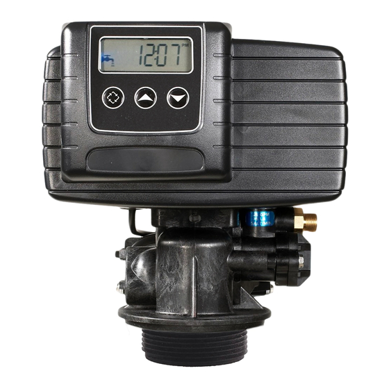
- Page 1 FLECK 5600SXT DOWNFLOW SERVICE MANUAL www.pentairaqua.com...
-
Page 2: Table Of Contents
TABLE OF CONTENTS JOB SPECIFICATION SHEET JOB SPECIFICATION SHEET ..........2 Job Number: ______________________________________________ INSTALLATION ..............3 Model Number: ____________________________________________ START-UP INSTRUCTIONS..........3 Water Hardness: __________________________________ ppm or gpg TIMER FEATURES ..............4 Capacity Per Unit: __________________________________________ TIMER OPERATION ..............5 Mineral Tank Size: ___________ Diameter: ________Height: ________ MASTER PROGRAMMING MODE CHART ......6 Salt Setting per Regeneration: ________________________________ MASTER PROGRAMMING MODE .........7... -
Page 3: Installation
INSTALLATION 10. On units with a by-pass, place in bypass position. Turn on the main water supply. Open a cold soft water tap nearby and let run a few minutes or until the system is free from Water Pressure foreign material (usually solder) that may have resulted A minimum of 20 pounds (1.4 bar) of water pressure is from the installation. -
Page 4: Timer Features
STARTUP INSTRUCTIONS CONTINUED Setting the Time of Day 1. Press and hold either the Up or Down buttons until the 5. Position the valve to the start of the brine tank fill cycle. programming icon replaces the service icon and the Ensure water goes into the brine tank at the desired parameter display reads TD. -
Page 5: Timer Operation
TIMER OPERATION Manually Initiating a Regeneration 1. When timer is in service, press the Extra Cycle button for 5 Meter Immediate Control seconds on the main screen. A meter immediate control measures water usage and 2. The timer advances to Regeneration Cycle Step #1 (rapid regenerates the system as soon as the calculated system rinse), and begins programmed time count down. -
Page 6: Master Programming Mode Chart
MASTER PROGRAMMING MODE CHART Before entering Master Programming, please contact your local professional water dealer. To enter CAUTION Master Programming, set time to 12:01 PM. Master Programming Options Abbreviation Parameter Option Options Abbreviation Gallons Display Format Liters dF1b Downflow/Upflow Single Backwash dF2b Downflow Double Backwash Fltr... -
Page 7: Master Programming Mode
MASTER PROGRAMMING MODE 2. Valve Type (Display Code VT) Press the Extra Cycle button. Use this display to set the Valve When the Master Programming Mode is entered, all available Type. The Valve Type setting specifies the type of cycle that the option setting displays may be viewed and set as needed. - Page 8 MASTER PROGRAMMING MODE CONTINUED 9. Safety Factor (Display Code SF) Press the Extra Cycle button. Use this display to set the Safety 5. Tank in Service (Display Code TS) Factor. This setting specifies what percentage of the system Press the Extra Cycle button. Use this display to set whether capacity will be held as a reserve.
- Page 9 MASTER PROGRAMMING MODE CONTINUED 16. Flow Meter Type (Display Code FM) Press the Extra Cycle button. Use this display to set the type 13. Regeneration Cycle Step Times of flow meter connected to the control. This option setting is Press the Extra Cycle button. Use this display to set the identified by “FM”...
-
Page 10: User Programming Mode
USER PROGRAMMING MODE 6. Press the Extra Cycle button. Use this display to set the Current Day of the Week. This option setting is identified by “CD” in the upper left hand corner of the screen. User Programming Mode Options Abbreviation Parameter Description... - Page 11 DIAGNOSTIC PROGRAMMING MODE CONTINUED 4. Press the Up button. Use this display to view the Hours in Service since the last regeneration cycle. This option setting is identified by “HR” in the upper left hand corner of the screen. 5. Press the Up button. Use this display to view the Volume Used since the last regeneration cycle.
-
Page 12: Control Valve Assembly
CONTROL VALVE ASSEMBLY 61500-56SE Rev A 12 • FLECK 5600SXT Downflow Service Manual... - Page 13 CONTROL VALVE ASSEMBLY CONTINUED Item No. Part No. Description Item No. Part No. Description 6 ....1 ..13546 ....Retainer, End Plug 1 ....1 ..61400-12 ..Valve Body Assy, 5600, Downflow, w/TOT O-ring 7 ....1 ..13296 ....Screw, Hex Washer, 6-20 x 1/2 1 ..
-
Page 14: Valve Powerhead Assembly
VALVE POWERHEAD ASSEMBLY 61501-56SXT Rev C Item No. Part No. Description Item No. Part No. Description Residential Valves 1 ....1 ..14448-100 ..Drive Housing Assy, with Pin, 56SXT ..41475 ....Transformer, 24V, 9.6VA, European 2 ....2 ..12473 ....Screw, Hex Wsh 10-24 x 5/8 19 ....1 .. -
Page 15: 3/4-Inch Turbine Meter Assembly
3/4-INCH PLASTIC PADDLE METER 3/4-INCH TURBINE METER ASSEMBLY ASSEMBLY BR60626 Item No. Part No. Description 1 ....1 ..19797 ....Meter Assy, 3/4" Dual Port, 2 ....2 ..19569 ....Clip, Flow Meter 3 ....2 ..13314 ....Screw, Slot Ind Hex, 8-18 x 0.60 4 ....1 .. -
Page 16: Bypass Valve Assembly (Plastic)
BYPASS VALVE ASSEMBLY (PLASTIC) 60049 Rev G Item No. Part No. Description 1 ....2 ..13305 ....O-ring, -119 2 ....2 ..13255 ....Clip, Mounting 3 ....2 ..13314 ....Screw, Hex Washer Head, 8-18 x 5/8 4A ....1 ..18706 ....Yoke, Plastic, 1-inch NPT .. -
Page 17: Bypass Valve Assembly (Metal)
BYPASS VALVE ASSEMBLY (METAL) 60040SS Rev R 60041SS Rev T Item No. Part No. Description 1 ....1 ..17290 ....Bypass Valve Body, 3/4-inch ..17290NP ..Bypass Valve Body, 3/4-inch Nickel Plated ..13399 ....Bypass Valve Body, 1-inch ..13399NP ..Bypass Valve Body, 1-inch, Nickel Plated 2 ....1 .. -
Page 18: 2300 Safety Brine Valve
2300 SAFETY BRINE VALVE 60027 Rev D Item No. Part No. Description 1 ....1 ..11942 ....Brine Valve Body 1/4-inch 2 ....1 ..10138 ....Ball, 3/8-inch 3 ....1 ..11566 ....Bull Stop 4 ....1 ..10328 ....Elbow, 1/4-inch x 1/4-inch T 5 ....2 .. -
Page 19: 2310 Safety Brine Valve
2310 SAFETY BRINE VALVE Item No. Part No. Description 1 ....1 ..19645 ....Safety Brine Valve Body 2 ....1 ..19803 ....Safety Brine Valve Arm Assembly 3 ....1 ..19804 ....Stud, 10-24 4 ....1 ..19805 ....Nut, 10-24 5 ....1 ..19652-01 ..Poppet and Seal 6 ....1 .. -
Page 20: Troubleshooting
TROUBLESHOOTING Problem Cause Correction Water conditioner fails to Electrical service to unit has been Assure permanent electrical service (check fuse, regenerate. interrupted plug, pull chain, or switch) Timer is defective. Replace timer. Power failure. Reset time of day. Hard water. By-pass valve is open. - Page 21 TROUBLESHOOTING CONTINUED Error Codes NOTE: Error codes appear on the In Service display. Error Error Type Cause Reset and Recovery Code Cam Sense The valve drive took longer Unplug the unit and examine the powerhead. Verify that all cam Error than 6 minutes to advance to switches are connected to the circuit board and functioning the next regeneration position...
-
Page 22: Water Conditioner Flow Diagrams
WATER CONDITIONER FLOW DIAGRAMS Single Backwash Positions Double Backwash Positions Black Cycle Cam Blue Cycle Cam Second Backwash Position (Double Backwash Units Only) (Part Number 17438) (Part Number 40609) Service Position Service Position 1. Backwash Position 1. First Backwash Position 2. -
Page 23: Wiring Diagram
WIRING DIAGRAM FLECK • 23 5600SXT Downflow Service Manual... -
Page 24: Service Instructions
SERVICE INSTRUCTIONS Timer Replacement To replace timer refer to Replacing Brine Valve, Injectors and Replacing Brine Valve, Injectors and Screen Screen, steps 1–3. 1. Turn off water supply to conditioner: 1. Remove the control valve back cover. Remove the control If the conditioner installation has a “three valve”... - Page 25 SERVICE INSTRUCTIONS CONTINUED Seal and Spacer Replacement To replace seals and spacers, refer to Replacing Brine Valve, Injectors and Screen, steps 1–3. 1. Remove the control valve back cover. Remove the control valve front cover. Disconnect the meter dome signal wire from the front cover and feed it back through the control.
-
Page 26: Flow Data & Injector Draw Rates
FLOW DATA & INJECTOR DRAW RATES 26 • FLECK 5600SXT Downflow Service Manual... -
Page 27: Service Assemblies
SERVICE ASSEMBLIES Air Check Meter 60002-34 .....Air Check #500 34-inch 60626 ......5600SXT Meter Assembly Brine Line Flow Controls Piston Assembly 60022-12 .....BLFC .125 gpm 60102-71 .....5600SXT Piston Assembly, Downflow 60022-25 .....BLFC .25 gpm 60022-50 .....BLFC .50 gpm Safety Brine Valves 60022-100 ....BLFC 1.0 gpm 60027-FFA ....Safety Brine Valve Body 2300 Fitting Facing Arm... - Page 28 For a detailed list of where Pentair trademarks are registered, please visit waterpurification.pentair.com/brands. § Pentair trademarks and logos are owned by Pentair plc or its affiliates. Third party registered and unregistered trademarks and logos are the property of their respective owners.
Need help?
Do you have a question about the FLECK 5600SXT and is the answer not in the manual?
Questions and answers