Pentair 5600SXT Service Manual
Hide thumbs
Also See for 5600SXT:
- Service manual (24 pages) ,
- Service manual (28 pages) ,
- User manual (37 pages)
Table of Contents
Advertisement
Advertisement
Table of Contents

Related Manuals for Pentair 5600SXT


Summary of Contents for Pentair 5600SXT
-
Page 3: Job Specification Sheet
Job Specification Sheet Job Number: __________________ Model Number: ________________ Water Hardness: ___________________ ppm or gpg Capacity Per Unit: ______________ Mineral Tank Size: ___________ Diameter: ___________ Height: Salt Setting per Regeneration: _____________________________________________ Type of Timer: 7 Day or 12 Day B. Meter Initiated Meter Size: 3/4”... -
Page 5: Start-Up Instructions
Start-Up Instructions The water softener should be installed with the inlet, outlet, and drain connections made in accordance with the manufacturer’s recommendations, and to meet applicable plumbing codes. Turn the manual regeneraton knob slowly in a clockwise direction until the program micro switch lifts on top of the first set of pins. -
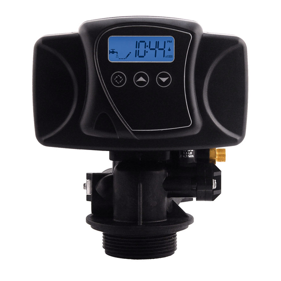
Page 7: Timer Features
Timer Features Setting the Time of Day Press and hold either the Up or Down buttons until the programming icon replaces the service icon and the parameter display reads TD. Adjust the displayed time with the Up and Down buttons. When the desired time is set, press the Extra Cycle button to resume normal operation. -
Page 8: Timer Operation
Timer Operation Meter Immediate Control A meter immediate control measures water usage and regenerates the system as soon as the calculated system capacity is depleted. The control calculates the system capacity by dividing the unit capacity (typically expressed in grains/unit volume) by the feedwater hardness and subtracting the reserve. Meter Immediate systems generally do not use a reserve volume. - Page 9 Timer Operation Control Operation During A Power Failure The SXT includes integral power backup. In the event of power failure, the control shifts into a power-saving mode. The control stops monitoring water usage, and the display and motor shut down, but it continues to keep track of the time and day for a minimum of 48 hours.
-
Page 10: Master Programming Mode Chart
Master Programming Mode Chart Master Programming Options Abbreviation Parameter Option Options Abbreviation Gallons Display Format Liters Cubic Meters St1b Standard Downflow/Upflow Single Backwash St2b Standard Downflow/Upflow Double Backwash Valve Type Fltr Filter UFbF Upflow Brine First Othr Other Meter (Flow) Delayed Meter (Flow) Immediate Control Type Time Clock... - Page 11 Master Programming Mode Chart Master Programming Options t0.7 3/4” Turbine Meter P0.7 3/4” Paddle Wheel Meter t1.0 1” Turbine Meter Flow Meter Type P1.0 1” Paddle Wheel Meter t1.5 1.5” Turbine Meter P1.5 1.5” Paddle Wheel Meter Generic or Other Meter Meter Pulse Setting Meter pulses per gallon for generic/other flow meter NOTES:...
-
Page 12: Master Programming Mode
Master Programming Mode When the Master Programming Mode is entered, all available option setting displays may be viewed and set as needed. Depending on current option settings, some parameters cannot be viewed or set.. Setting the Time of Day Press and hold either the Up or Down buttons until the programming icon replaces the service icon and the parameter display reads TD. - Page 13 Master Programming Mode 2. Valve Type (Display Code VT) Press the Extra Cycle button. Use this display to set the Valve Type. The Valve Type setting specifies the type of cycle that the valve follows during regeneration. Note that some valve types require that the valve be built with specific subcomponents.
- Page 14 Master Programming Mode 5. Tank in Service (Display Code TS) Press the Extra Cycle button. Use this display to set whether tank one or tank two is in service. This option setting is identified by “TS” in the upper left hand corner of the screen. This parameter is only available if the number of tanks has been set to 2.
- Page 15 Master Programming Mode 8. Reserve Selection (Display Code RS) Press the Extra Cycle button. Use this display to set the Safety Factor. Use this display to select the type of reserve to be used in your system. This setting is identified by “RS” in the upper left-hand corner of the screen. The reserve selection parameter is only available if the control type has been set to one of the metered options.
- Page 16 Master Programming Mode 11. Day Override (Display Code DO) Press the Extra Cycle button. Use this display to set the Day Override. This setting specifies the maximum number of days between regeneration cycles. If the system is set to a timer-type control, the day override setting determines how often the system will regenerate.
- Page 17 Master Programming Mode 14. Day of Week Settings Press the Extra Cycle button. Use this display to set the regeneration schedule for a system configured as a Day of Week control. The different days of the week are identified as D1, D2, D3, D4, D5, D6, and D7 in the upper left-hand corner of the display.
- Page 18 Master Programming Mode 17. Meter Pulse Setting (Display Code K) Press the Extra Cycle button. Use this display to specify the meter pulse setting for a non-standard flow meter. This option setting is identified by “K” in the upper left-hand corner of the screen. Use the Up and Down buttons to enter the meter constant in pulses per unit volume..
-
Page 19: User Programming Mode
User Programming Mode User Programming Mode Options Abbreviation Parameter Description Day Override The timer’s day override setting Regeneration Time The time of day that the system will regenerate (meter delayed, timeclock, and day-of-week systems) Feed Water Hardness The hardness of the inlet water - used to calculate system capacity for metered systems Reserve Capacity... - Page 20 User Programming Mode Press the Extra Cycle button. Use this display to adjust the Fixed Reserve Capacity. This option setting is identified by “RC” in the upper left-hand corner of the screen.. Press the Extra Cycle button. Use this display to set the Current Day of the Week. This option setting is identified by “CD”...
- Page 23 Notes Page 23...
-
Page 24: Control Valve Assembly
Control Valve Assembly Page 24... - Page 25 Control Valve Assembly Item No. Quantity Part No. Description 1......2-4......13255........adapter clip (clock or meter) 2......5......13242........seal ......5......40628........seal, 559PE 3......1......61400-12......valve body assembly, 1 dist......1......61400-11......valve body assembly, 3/4 dist. 4......1......
-
Page 26: Valve Powerhead Assembly
Valve Powerhead Assembly 61501-56SE_REVA Page 26... - Page 27 Valve Powerhead Assembly Item No. Quantity Part No. Description 1...... 1......26001-02.....Housing, Control Valve Drive 2...... 2......12473......Screw, Hex Wsh 10-24 x 5/8 3...... 1......19474......Harness, Power, 56SXT, Elect 4...... 1......13299......Washer, Spring, 3/8 5...... 1......13017......Gear, Idler 6......
- Page 28 3/4” Turbine Meter Assembly Item No. Quantity Part No. Description 1....2..... 13314.......Screw, Hex Washer, 8-18 x 5/8 2....2..... 19569.......Clip, Flow Meter 3....1..... 19797.......Meter Body Assembly, 3/4” Turbine 4....4..... 13305.......O-ring, 119 5.
-
Page 29: Bypass Valve Assembly (Plastic)
Bypass Valve Assembly (Plastic) Item No. Quantity Part No. Description 1....2..... 13305.......O-ring, -119 2....2..... 13255.......Clip, Mounting 3....2..... 13314.......Screw, Hex Washer Head, 8-18 x 5/8 4A....1..... 18706.......Yoke, Plastic, 1” NPT ..........18706-02....Yoke, Plastic, 3/4” NPT 4B.... -
Page 30: Bypass Valve Assembly (Metal)
Bypass Valve Assembly (Metal) Item No. Quantity Part No. Description 1....1..... 17290.......bypass valve body, 3/4” ...... 1..... 17290NP....bypass valve body, 3/4” nickel plated ...... 1..... 13399.......bypass valve body, 1” ...... 1..... 13399NP....bypass valve body, 1”, nickel plated 2. -
Page 31: 2300 Safety Brine Valve
2300 Safety Brine Valve Item No. Quantity Part No. Description 1....1..... 11942.......brine valve body 1/4” NPT 2....1..... 10138.......ball, 3/8” 3....1..... 11566.......bull stop 4....1..... 10328.......elbow, 1/4” x 1/4” T 5. -
Page 32: 2310 Safety Brine Valve
2310 Safety Brine Valve Item No. Quantity Part No. Description 1....1..... 19645.......safety brine valve body 2....1..... 19803.......safety brine valve arm assembly 3....1..... 19804.......stud, 10-24 4....1..... 19805.......nut, 10-24 5....1..... 19652-01....poppet and seal 6. -
Page 33: Troubleshooting
Troubleshooting Problem Cause Correction 1. Water conditioner fails to A. Electrical service to unit has A. Assure permanent electrical service regenerate. been interrupted (check fuse, plug, pull chain, or switch) B. Timer is defective. B. Replace timer. C. Power failure. C. - Page 34 Troubleshooting Problem Cause Correction 8. Softener fails to draw brine. A. Drain line flow control is A. Clean drain line flow control. plugged. B. Injector is plugged. B. Clean injector C. Injector screen plugged. C. Clean screen. D. Line pressure is too low. D.
-
Page 36: Water Conditioner Flow Diagrams
Water Conditioner Flow Diagrams Single Backwash Positions Double Backwash Positions Black Cycle Cam Blue Cycle Cam (Part Number 17438) (Part Number 40609) Service Position Service Position 1. Backwash Position 1. First Backwash Position 2. Brine/Slow Rinse Position 2. Brine/Slow Rinse Position 3. - Page 37 Water Conditioner Flow Diagrams Backwash Position Brine/Slow Rinse Position Page 37...
- Page 38 Water Conditioner Flow Diagrams Second Backwash Position (Double Backwash Units Only) Rapid Rinse Position Page 38...
- Page 39 Water Conditioner Flow Diagrams Brine Tank Fill Position Page 39...
-
Page 40: Wiring Diagram
Wiring Diagram Page 40... -
Page 41: Service Instructions
Service Instructions Replacing Brine Valve, Injectors and Screen Turn off water supply to conditioner:. If the conditioner installation has a “three valve” bypass system, first open the valve in the bypass. line, then close the valves at the conditioner inlet and outlet.. If the conditioner has an integral bypass valve, put it in the Bypass position.. - Page 42 Service Instructions Timer Replacement To replace timer refer to Replacing Brine Valve, Injectors and Screen, steps 1–3. Remove the control valve back cover. Remove the control valve front cover. Disconnect the meter dome sig- nal wire from the front cover and feed it back through the control. Remove screw and washer at drive yoke.
- Page 43 Service Instructions Seal and Spacer Replacement To replace seals and spacers, refer to Replacing Brine Valve, Injectors and Screen, steps 1–3. Remove the control valve back cover. Remove the control valve front cover. Disconnect the meter dome sig- nal wire from the front cover and feed it back through the control. Remove screw and washer at drive yoke.
-
Page 44: Service Assemblies
12086....washer flow 1.5 GPM 12087....washer flow 2.0 GPM Seal & Spacer Kits 12088....washer flow 2.4 GPM 60125....5600SXT seal and spacer kit 12089....washer flow 3.0 GPM 60125-20..seal & spacer kit, top 12090....washer flow 3.5 GPM 12091.... - Page 45 Notes Page 45...
- Page 46 Notes Page 46...
- Page 47 Notes Page 47...
- Page 48 P/N 42684 Rev. B 6/25/08...
Need help?
Do you have a question about the 5600SXT and is the answer not in the manual?
Questions and answers