Pentair Fleck 2510 Service Manual
Hide thumbs
Also See for Fleck 2510:
- Service manual (37 pages) ,
- Service manual (36 pages) ,
- Service manual (28 pages)

Related Manuals for Pentair Fleck 2510


Summary of Contents for Pentair Fleck 2510
- Page 1 CLICK ANYWHERE on THIS PAGE to RETURN to WATER SOFTENER MANUALS at InspectApedia.com Model 2510 & 2510 Econominder Service Manual IMPORTANT: Fill in Pertinent Information on Page 3 for Future Reference...
-
Page 2: Table Of Contents
Table of Contents Job Specifi cation Sheet ............................3 Installation Instructions ............................4 Start-Up Instructions .............................. 5 3200 Timer Setting Procedure ..........................6 3210 Timer Settings............................... 7 3200 & 3210 Timer Series ............................. 8 3200 Timer Assembly ............................10 3210 Timer Assembly ............................12 Powerhead Assembly ............................ -
Page 3: Job Specifi Cation Sheet
Job Specifi cation Sheet Job Number: __________________ Model Number: ________________ Water Hardness: ___________________ ppm or gpg Capacity Per Unit: ______________ Mineral Tank Size: ___________ Diameter: ___________ Height: Salt Setting per Regeneration: _____________________________________________ Type of Timer: 7 Day or 12 Day B. -
Page 4: Installation Instructions
Installation Instructions WATER PRESSURE: A minimum of 20 pounds of water pressure (1.3 bar) is required for regeneration valve to operate effectively. ELECTRICAL FACILITIES: An uninterrupted alternating current (A/C) supply is required. Note: Other voltages are available. Please make sure your voltage supply is compatible with your unit before installation. EXISTING PLUMBING: Condition of existing plumbing should be free from lime and iron buildup. -
Page 5: Start-Up Instructions
Start-Up Instructions The water softener should be installed with the inlet, outlet, and drain connections made in accordance with the manufacturer’s recommendations, and to meet applicable plumbing codes. Turn the manual regeneraton knob slowly in a clockwise direction until the program micro switch lifts on top of the fi... -
Page 6: 3200 Timer Setting Procedure
3200 Timer Setting Procedure How To Set Days On Which Water Conditioner Is To Regenerate (Figure 2): Rotate the skipper wheel until the number “1” is at the red pointer. Set the days that regeneration is to occur by sliding tabs on the skipper wheel outward to expose trip fi... -
Page 7: 3210 Timer Settings
3210 Timer Settings Typical Programming Procedure How To Manually Regenerate Your Water Conditioner At Any Time: Calculate the gallon capacity of the system, subtract the necessary reserve requirement and set the gallons Turn the manual regeneration knob clockwise. available opposite the small white dot on the program This slight movement of the manual regeneration wheel gear. -
Page 8: 3200 & 3210 Timer Series
3200 & 3210 Timer Series Regeneration Cycle Program Setting Procedure (Downfl ow) How To Set The Regeneration Cycle Program: The regeneration cycle program on your water conditioner has been factory preset, however, portions of the cycle or program may be lengthened or shortened in time to suit local conditions. - Page 9 Notes Page 9...
-
Page 10: 3200 Timer Assembly
3200 Timer Assembly 61502-3200_REVA For Service Assembly Numbers, See the Back of this Manual Page 10... - Page 11 3200 Timer Assembly Item No. Quantity Part No. Description 1 ..... 1 .......13870 ......Housing, Timer, 3200 2 ..... 1 .......14265 ......Clip, Spring 3 ..... 3 .......14087 ......Insulator 4 ..... 1 .......10896 ......Switch, Micro 5 ..... 1 .......15320 ......Switch, Micro, Timer 6 .....
-
Page 12: 3210 Timer Assembly
3210 Timer Assembly 61502-3210_REVA For Service Assembly Numbers, See the Back of this Manual Page 12... - Page 13 3210 Timer Assembly Item No. Quantity Part No. Description 1 ..... 1 .......13870 ......Housing, Timer, 3200 2 ..... 1 .......13802 ......Gear, Cycle Actuator 3 ..... 1 .......40096-02 ....Dial, 2 AM Regen Assy, Black 4 ..... 1 .......13886 ......Knob, 3200 5 ..... 4 .......13296 ......Screw, Hex Wsh, 6-20 x 1/2 6 .....
-
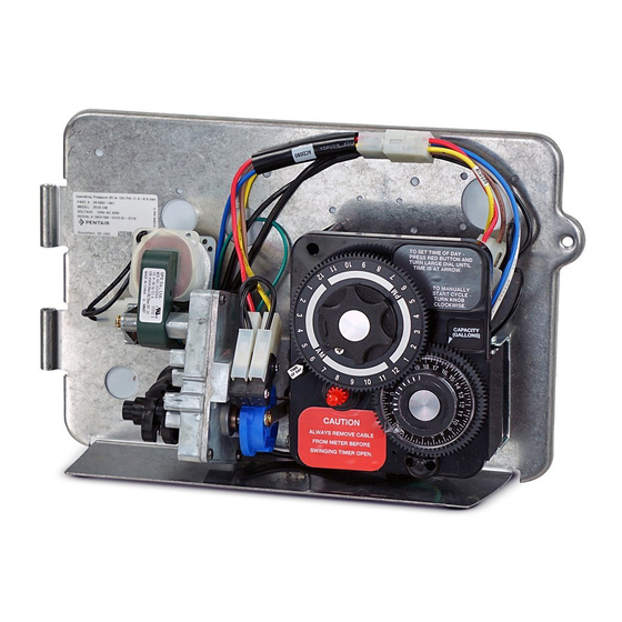
Page 14: Powerhead Assembly
Powerhead Assembly (Designer) 61501_2510REVB For Service Assembly Numbers, See the Back of this Manual Page 14... - Page 15 Powerhead Assembly (Designer) Item No. Quantity Part No. Description 1 ..... 1 .......40264 ......Backplate, SS/SVO, W-T-Screws 2 ..... 1 ............3200, Timer 7 or 12 Day 3 ..... 1 .......11838 ......Power Cord 4 ..... 1 .......13547 ......Strain Relief 5 ..... 1 .......40400 ......Harness, Drive, Designer/Environmental 8 .....
-
Page 16: Powerhead Assembly (Environmental)
Powerhead Assembly (Environmental) For Service Assembly Numbers, See the Back of this Manual Page 16 Page 16... - Page 17 Powerhead Assembly (Environmental) Item No. Quantity Part No. Description 1 ....1 ......18697-15 ....Backplate, Hinged, 2900 2 ....1 ............Timer: - 3200 7 Day - 3200 12 Day - 3210 Meter 3 ....1 ......11839 ......Power Cord, 12’ Fleck 4 ....1 ......13547 ......Strain Relief, Flat Cord 5 ....1 ......40400 ......
-
Page 18: Manual Powerhead Assembly
Manual Powerhead Assembly 60409REVA Item No. Quantity Part No. Description 1 ..... 1 .......12593 ......Backplate, Manual 2 ..... 1 .......12592 ......Bracket, Lever Position 3 ..... 1 .......12596 ......Screw, Spec Mach, 1/4 - 20 x 1/2 4 ..... 1 .......12707 ......Washer, Spring 6 ..... - Page 19 Notes Page 19...
-
Page 20: Control Valve Assembly
Control Valve Assembly 61500_2510REVB For Service Assembly Numbers, See the Back of this Manual Page 20... - Page 21 Control Valve Assembly Item No. Quantity Part No. Description 1 ...... 1 ......19328 ......Valve Body, 2510 2 ..... 1 .......11385-01 .....Housing, Flow Control, Plastic 3 ..... 1 .......11183 ......O-ring, -017 4 ..... 1 .......12408 ......Washer, Flow, 7.0 GPM 5 ..... 1 .......18312 ......Retainer, Drain 6 .....
-
Page 22: Softener & Filter Conversion Kits
Softener & Filter Conversion Kits 61671REVC Item No. Part No. Description 1 ....61671-01 ..Piston Conversion w/Seal & Spacer 2510 NHWBP 1600 2 ....61671-00 ..Piston Kit w/Seal & Spacer 2510 NHWBP Filter NOTE: For optimal seal life, the use of lubricants is not recommended. Page 22... -
Page 23: Meter Assembly
Meter Assembly 60088 Item No. Quantity Part No. Description 1 ..... 4 .......12473 ......Screw - Meter Cover Assembly 2 ..... 1 .......15659 ......Meter Cover Assy. - Ext., Rt. Angle (Not Shown) ....... 1 .......15452 ......Meter Cap Assy, 3/4” to 2”, Std, Rt Ang/90, Plastic Paddle 3 ..... -
Page 24: 1600 Brine System Assembly
1600 Brine System Assembly 60029REVC Item No. Quantity Part No. Description 1 ..... 2 .......10332 ......Fitting, Insert, 3/8 2 ..... 1 .......12767 ......Screen, Brine 3 ..... 1 .......10328 ......Fitting, Elbow, 90 Deg. 1/4 PT x 3/8Tube 4 ..... 1 .......60020-25 ....BLFC, .25 GPM, 1600 4 ..... -
Page 25: 1650 Brine System Assembly
1650 Brine System 60011 Item No. Quantity Part No. Description 60011 Brine Valve Assembly, Includes Items 3-15 (Less BLFC 60010-) 1 ..... 1 .......10328 ......Elbow, 90 1/4 NPT x 3/8 3 ..... 3 .......10332 ......Insert, 3/8 4 ..... 1 .......10330 ......Sleeve, 3/8 Nut Brine 5 ..... -
Page 26: Bypass Valve Assembly (Plastic)
Bypass Valve Assembly (Plastic) 60049REVD Item No. Quantity Part No. Description 1 ....2 ......13305 ......O-ring, -119 2 ....2 ......13255 ......Clip, Mounting 3 ....2 ......13314 ......Screw, Slot Ind Hex, 8-18 x .60 4A....1 ......18706 ......Yoke, 1”, NPT, Plastic ..........18706-02 .... -
Page 27: Bypass Valve Assembly (Metal)
Bypass Valve Assembly (Metal) Item No. Quantity Part No. Description 1 ..... 1 .......40614 ......Bypass Body, 3/4” ..........40634 ......Bypass Body, 1”, SS 2 ..... 1 .......14105 ......Seal, Bypass, 560CD 3 ..... 1 .......11972 ......Plug, Bypass 4 ..... 1 .......11978 ......Side Cover 5 ..... -
Page 28: 2300 Safety Brine Valve
2300 Safety Brine Valve 60027REVA Item No. Quantity Part No. Description 1 ..... 1 .......60027-00 ....Safety Brine Valve, 2300, Less Elbow 2 ..... 1 .......10138 ......Ball, 3/8”, Brass 3 ..... 1 .......11566 ......Ball Stop, Slow Fill 4 ..... 1 .......10328 ......Fitting, Elbow, 90 Deg. 1/4 NPT x 3/8 Tube 5 ..... -
Page 29: 2310 Safety Brine Valve
2310 Safety Brine Valve Item No. Quantity Part No. Description 1 ....1 ......19645 ......Body, Safety Brine Valve, 2310 2 ....1 ......19803 ......Safety Brine Valve Assy 3 ....1 ......19804 ......Screw, Sckt Hd, Set, 10-24 x .75 4 ....1 ......19805 ......Nut, Hex, 10-24, Nylon Black 5 ....1 ......19652-01 .... -
Page 30: Service Instructions
Service Instructions Tools Used in the Seal and Spacer Replacement Description Part No. Nut Driver ......12664 Socket Adapter ....16906 Socket 7/16” ......12665 Seal Hook ......12874 Puller ........13061 Stuffer ........11098 Page 30... -
Page 31: Seal & Spacer Replacement
Seal & Spacer Replacement Turn off water supply to valve. Next, cycle valve to backwash position, then to service. Now remove electrical plug from outlet. Remove control box cover. Disconnect the brine line from the injector housing to the brine valve (if your unit has timed brine tank fi... - Page 32 Seal & Spacer Replacement Alternately remove the remaining seals and spacers in accordance with steps No. 6 and 8. The last or end spacer odes not have any holes for the pins of the spacer tool to engage, therefore if the end spacer does not come out on the fi...
-
Page 33: Troubleshooting
Troubleshooting Problem Cause Correction 1. Water conditioner fails to A. Electrical service to unit has A. Assure permanent electrical service regenerate. been interrupted (check fuse, plug, pull chain, or switch) B. Timer is defective. B. Replace timer. C. Power failure. C. - Page 34 Troubleshooting Problem Cause Correction 8. Softener fails to draw brine. A. Drain line fl ow control is A. Clean drain line fl ow control. plugged. B. Injector is plugged. B. Clean injector C. Injector screen plugged. C. Clean screen. D. Line pressure is too low. D.
-
Page 35: Flow Data & Injector Draw Rates
Flow Data & Injector Draw Rates Page 35... -
Page 36: Wiring Diagram
Wiring Diagram Page 36... -
Page 37: Service Assemblies
Service Assemblies 24 Hour Gear Drives 40096-02 ..Dial 2AM Regen Assy, Black 60050-21 ..Drive Assy, 2750, STF, 120V Softener 40096-24 ..Dial 12AM Regen Assy, Black 60519-02 ..Gear Assy, 3200, 24 Hour 2 Times/Day Injectors 60519-03 ..Gear Assy, 3200, 24 Hour 3 Times/Day 60480-XX..1600 Injector Assy 60519-04 ..Gear Assy, 3200, 24 Hour 4 Times/Day 60519-06 ..Gear Assy, 3200, 24 Hour (12:00) 6 Times/Day... - Page 38 Notes Page 38...
- Page 39 Notes Page 39...
- Page 40 P/N 40097 Rev. J 1/09...
Need help?
Do you have a question about the Fleck 2510 and is the answer not in the manual?
Questions and answers