Campbell CR1000 Operator's Manual
Measurement and control system
Hide thumbs
Also See for CR1000:
- Operator's manual (588 pages) ,
- Operator's manual (628 pages) ,
- Operator's manual (678 pages)
Table of Contents
Advertisement
Quick Links
Download this manual
See also:
Operator's Manual
Advertisement
Table of Contents
Troubleshooting

Subscribe to Our Youtube Channel
Related Manuals for Campbell CR1000


Summary of Contents for Campbell CR1000
- Page 1 CR1000 Measurement and Control System Revision: 7/08 C o p y r i g h t © 2 0 0 0 - 2 0 0 8 C a m p b e l l S c i e n t i f i c ,...
- Page 2 Warranty and Assistance The CR1000 MEASUREMENT AND CONTROL SYSTEM is warranted by CAMPBELL SCIENTIFIC, INC. to be free from defects in materials and workmanship under normal use and service for thirty-six (36) months from date of shipment unless specified otherwise. Batteries have no warranty.
-
Page 3: Table Of Contents
PDF viewers note: These page numbers refer to the printed version of this document. Use the Adobe Acrobat® bookmarks tab for links to specific sections. 1. Introduction...............1-1 2. Quickstart Tutorial............2-1 2.1 Primer – CR1000 Data Acquisition............2-1 2.1.1 Components of a Data Acquisition System ........ 2-1 2.1.1.1 Sensors ................2-1 2.1.1.2 Datalogger ................. 2-1 2.1.1.3 Data Retrieval.............. - Page 4 CR1000 Table of Contents 3.1.7 Security..................3-10 3.1.8 Care and Maintenance ............... 3-10 3.1.8.1 Protection from Water ............. 3-10 3.1.8.2 Protection from Voltage Transients ......... 3-11 3.1.8.3 Calibration ............... 3-11 3.1.8.4 Internal Battery ..............3-11 3.2 PC Support Software ................3-11 3.3 Specifications..................
- Page 5 8.1 DevConfig .................... 8-1 8.2 Sending the Operating System ............. 8-2 8.2.1 Sending OS with DevConfig ............8-2 8.2.2 Sending OS to Remote CR1000 ..........8-4 8.2.3 Sending OS Using CF Card ............8-4 8.3 Settings ....................8-4 8.3.1 Settings via DevConfig ............... 8-4 8.3.1.1 Deployment Tab..............
- Page 6 8.3.4.3 Priorities................8-14 9. CR1000 Programming ..........9-1 9.1 Inserting Comments into Program ............9-1 9.2 Uploading CR1000 Programs............... 9-1 9.3 Writing CR1000 Programs ..............9-1 9.3.1 Short Cut Editor and Program Generator........9-1 9.3.2 CRBASIC Editor ................ 9-2 9.3.3 Transformer................. 9-2 9.4 Numerical Formats ................
- Page 7 CR1000 Table of Contents 10. CRBASIC Programming Instructions ....10-1 10.1 Program Declarations ............... 10-1 10.2 Data Table Declarations ..............10-3 10.2.1 Data Table Modifiers.............. 10-3 10.2.2 On-Line Data Destinations ............. 10-3 10.2.3 Data Storage Output Processing ..........10-4 10.2.3.1 Single-Source ..............10-4 10.2.3.2 Multiple-Source ............
- Page 8 CR1000 Table of Contents 11. Programming Resource Library ......11-1 11.1 Field Calibration of Linear Sensors (FieldCal)......... 11-1 11.1.1 CAL Files................11-1 11.1.2 CRBASIC Programming............11-2 11.1.3 Calibration Wizard Overview ..........11-2 11.1.4 Manual Calibration Overview..........11-2 11.1.4.1 Single-point Calibrations (zero or offset)...... 11-3 11.1.4.2 Two-point Calibrations (multiplier / gain) ....
- Page 9 11.11.3 Example NSEC Programming ..........11-59 11.12 Bool8 Data Type ................11-61 11.13 Burst Mode ................... 11-64 11.13.1 CR1000 Burst Mode ............11-64 11.13.2 Comparing CR1000 and CR10X Burst Modes ....11-65 11.13.3 Burst Mode Programming........... 11-66 11.14 String Operations ................11-66 11.14.1 Operators................11-66 11.14.2 Concatenation..............
- Page 10 CR1000 Table of Contents 12.6 File Management ................12-7 12.6.1 File Attributes ................. 12-9 12.6.2 CF Power-up ................. 12-10 12.7 File Names..................12-14 13. Telecommunications and Data Retrieval ... 13-1 13.1 Hardware and Carrier Signal ............13-1 13.2 Protocols ................... 13-2 13.3 Initiating Telecommunications ............
- Page 11 CR1000 Table of Contents 15.2.6 Modbus Slave over IP with NL100......... 15-8 15.2.6.1 Configuring the NL100 ..........15-8 15.2.6.2 Configuring the CR1000 ..........15-12 15.2.6.3 ModBus tidBytes............15-13 16. Support Software..........16-1 16.1 Short Cut ..................16-1 16.2 PC200W ................... 16-1 16.3 Visual Weather .................
- Page 12 E. FP2 Data Format ............E-1 Index to Sections ............Index-1 Figures 2.1-1. CR1000 Wiring Panel............... 2-3 2.1-2. Single-ended and Differential Input Channels........2-4 2.1-3. Single-ended and Differential Analog Sensor Wiring ...... 2-5 2.1-4. Half and Full Bridge Wiring ............. 2-6 2.1-5.
- Page 13 4.4-3. Panel Temperature Gradients during 80 to 25°C Change....4-25 4.4-4. Diagram of Junction Box..............4-30 4.5-1. Schematic of a Pulse Sensor on a CR1000 ........4-31 4.5-2. Pulse Input Types ................4-32 4.5-3. Amplitude reduction of pulse-count waveform before and after 1 μs time constant filter.
- Page 14 11.12-2. Bool8 data from ................ 11-63 11.12-3. Bool8 data from ................ 11-64 12.6-1. Summary of the Effect of CF Data Options on CR1000 Data..12-10 14.2-1. PakBus Network Addressing. PakBus addresses are shown in parentheses after each datalogger in the network......14-2 14.6-1.
- Page 15 0°C)....................4-25 4.4-2. Voltage Range for Maximum Thermocouple Resolution (with reference temperature at 20°C) ............4-27 4.4-3. Limits of Error on CR1000 Thermocouple Polynomials (Relative to NIST Standards) ................4-28 4.4-4. Reference Temperature Compensation Range and Polynomial Error Relative to NIST Standards ............4-28 4.4-5.
- Page 16 CR1000 Table of Contents B-1. Common Uses of the Status Table ............. B-1 B-2. Status / Setting Fields and Descriptions ..........B-2 B-3. Settings..................... B-10 C-1. CS I/O Pin Description............... C-1 C-2. Computer RS-232 Pin-Out..............C-2 C-3. Standard Null Modem Cable or Adapter Pin Connections....C-3 E-1.
- Page 17 11.8-4. CRBASIC Code: measures sensors and sends data out the RS-232 port in Printable ASCII format. Accepts “C” command to set the CR1000 clock..............11-51 11.9-1. Using TrigVar to Trigger Data Storage ........11-57 11.11-1. CRBASIC Code: Using NSEC data type on a 1 element array.11-59 11.11-2.
- Page 18 CR1000 Table of Contents...
-
Page 19: Introduction
The limits of the CR1000 are defined by our customers. Our intent with the CR1000 manual is to guide you to the tools you need to explore the limits of your application. - Page 20 Section 1. Introduction This is a blank page.
-
Page 21: Quickstart Tutorial
CR1000s measure electrical signals and convert the measurement to engineering units, perform calculations and reduce data to statistical values. Every measurement does not need to be stored. The CR1000 will store data in memory awaiting transfer to the PC via external storage devices or telecommunications. -
Page 22: Cr1000 Mounting
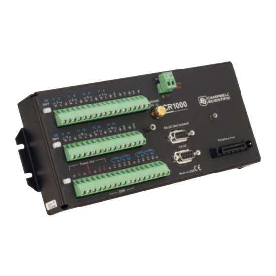
See FIGURE 2.1-1. 2.1.4 Battery Backup A lithium battery backs up the CR1000 clock, program, and memory if it loses power. 2.1.5 Power Supply The CR1000 can be powered by a nominal 12 volt DC source through the... - Page 23 RS-232 (Not Isolated) POWER OUT COM1 COM2 COM3 COM4 Rx Tx Rx Tx Rx Tx Rx CS I/O PERIPHERAL PORT MADE IN USA 12 V SDM Connections Control I/O Peripheral Port Power Ground (G) Switched 12 Volts FIGURE 2.1-1. CR1000 Wiring Panel...
-
Page 24: Analog Sensors
Section 2. Quickstart Tutorial 2.1.6 Analog Sensors Analog sensors output continuous voltages that vary with the phenomena measured. Analog sensors connect to analog terminals. Analog terminals are configured as single-ended (measured with respect to ground) or differential (high input measured with respect to the low input of a channel pair (FIGURE 2.1-3)). Analog channels are configured individually as 8 differential or 16 single ended Channels (FIGURE 2.1-2). - Page 25 Section 2. Quickstart Tutorial Sensor Wired to Single-Ended Channel #2 Sensor Sensor Wired to Differential Channel #1 Sensor FIGURE 2.1-3. Single-ended and Differential Analog Sensor Wiring...
-
Page 26: Bridge Sensors
Bridge sensors change resistance with respect to environmental change. Resistance is determined by measuring the difference between the excitation voltage supplied to the bridge by the CR1000 and the voltage detected by the CR1000 returning from the bridge. The CR1000 supplies a precise excitation voltage via excitation terminals. -
Page 27: Pulse Sensors
FIGURE 2.1-6. Anemometer Wired to Pulse Channel #1 2.1.9 Digital I/O Ports The CR1000 has 8 Digital I/O ports selectable, under program control, as binary inputs or control outputs. These ports have multiple function capability including: edge timing, device driven interrupts, switch closure pulse counting, high frequency pulse counting, asynchronous communications, SDI-12 communications, SDM communications, and as shown in FIGURE 2.1-7,... -
Page 28: Rs-232 Sensors
Section 2. Quickstart Tutorial Digital I/O Ports Used to Control/Monitor Pump 110 VAC CR10 ACL1 Line Pump Monitor C1 - Used as input to monitor pump status. C2 - Used as output to switch power to a pump via a solid state relay. FIGURE 2.1-7. -
Page 29: Hands-On Exercise – Measuring A Thermocouple
Section 2. Quickstart Tutorial 2.2 Hands-on Exercise – Measuring a Thermocouple This tutorial is a stepwise procedure for configuring a CR1000 to make a simple thermocouple measurement and send the resulting data to a PC. Discussions include programming, real-time data monitoring, collecting data, and viewing data. -
Page 30: Programming With Short Cut
Resource CD or at www.campbellsci.com. When PC200W is first opened, the EZSetup Wizard is launched. Click the Next button and follow the prompts to select the CR1000, the COM port on the computer that will be used for communications, 115200 baud, and PakBus Address 1. - Page 31 When things settled out, the micro-volt meter was read, and the value looked up in the appropriate table in the reference book to determine the temperature. Then along came Eric and Evan Campbell. Campbell Scientific designed the first CR7 datalogger to make thermocouple measurements without the need of vacuum flasks, third junctions, or reference books.
- Page 32 Support.” Choose “Campbell Scientific, Inc.” On the “1. New/Open” page, click [New Program]. Use the drop-down list box that appears to select CR1000. Click [OK]. Enter a 1 second Scan Interval and click [OK]. Click on [Next>] to progress to “2. Sensors” page.
- Page 33 FIGURE 2.2-4. Short Cut Sensors Page Click on Wiring Diagram to view the sensor wiring diagram, as shown in FIGURE 2.2-5. Wire the Type T Thermocouple (provided) to the CR1000 as shown on the diagram. Click on 3. Outputs to continue with Step 3.
- Page 34 As shown in FIGURE 2.2-7, any errors the compiler may have detected are displayed, along with the names of the files that were created. The file Quickstart.CR1 is the program file that is to be sent to the CR1000. Quickstart.def is a summary of the sensor wiring and measurement labels.
-
Page 35: Connecting To The Datalogger
FIGURE 2.2-7. Short Cut Finish Page 2.2.2.2 Connecting to the Datalogger From the PC200W Clock / Program tab, click on the Connect button to establish communications with the CR1000 (FIGURE 2.2-8). When communications have been established, the text on the button will change to Disconnect. -
Page 36: Synchronizing The Clocks
The Monitor Data window (FIGURE 2.2-9) is used to display the current sensor measurement values from the Public Table, and the most recent data from the OneMin table. After sending a program to the CR1000, a good practice is to monitor the measurements to ensure they are reasonable. -
Page 37: Viewing Data
Section 2. Quickstart Tutorial FIGURE 2.2-10. PC200W Collect Data Tab 2.2.2.7 Viewing Data To view the collected data, click on the View button (located in the upper right-central portion of the main screen). Options are accessed by using the menus or by selecting the toolbar icons. Move and hold the mouse over a toolbar icon for a few seconds for a brief description of that icon's function. -
Page 38: Pc200W View Data Utility
Section 2. Quickstart Tutorial Show graph Open file Expand tabs FIGURE 2.2-11. PC200W View Data Utility Close the graph and view screens, and close PC200W. 2-18... -
Page 39: Cr1000 Overview
FIGURE 3.1-1. Principal Features of CR1000 Data Acquisition Systems As a simple concept, the CR1000 is a multimeter with memory and timekeeping. It is one part of a data acquisition system. To acquire quality data, suitable sensors and reliable telecommunications devices are also required. -
Page 40: Sensor Support
3.1.2 Input / Output Interface: The Wiring Panel The wiring panel of the CR1000 is the interface to all CR1000 functions. Most CR1000 functions are best introduced by reviewing features of the CR1000 wiring panel. FIGURE 2.1-1 illustrates the wiring panel and some CR1000 functions accessed through it. - Page 41 9-Pin RS-232: 1 port (Computer RS-232) configurable for serial input. 3.1.2.2 Voltage Outputs The CR1000 supplies precision voltage excitation for resistive measurements through the following output channels: Switched Analog Voltage Output (Excitation): 3 channels (Vx/VX1 (VX1 (EX1)) – Vx/VX3 (EX3)) for precise voltage excitation ranging from -2500...
- Page 42 Section 3. Overview The CR1000 can be used as a PLC (programmable logic controller). Utilizing peripheral relays and analog output devices, the CR1000 can manage binary and variable control devices through the following output channels: Read more! See Section 5.4 Control Output.
- Page 43 Read more! See Section 13 Telecommunication and Data Retrieval and Section 14 PakBus Overview. The CR1000 is equipped with several communications ports. Communication ports allow the CR1000 to communicate with other computing devices, such as a PC, or with other Campbell Scientific dataloggers. NOTE...
-
Page 44: Power Requirements
3.1.3 Power Requirements Read more! See Section 6 Power Supply. The CR1000 operates from a DC power supply with voltage ranging from 9.6 to 16 V, and is internally protected against accidental polarity reversal. The CR1000 has modest input power requirements. In low power applications, it can operate for several months on non-rechargeable batteries. -
Page 45: Memory And Data Storage
A program is created on a PC and sent to the CR1000. The CR1000 can store a number of programs in memory, but only one program is active at a given time. Three Campbell Scientific software applications, Short Cut, CRBASIC Editor, and Transformer Utility create CR1000 programs. -
Page 46: Communications
Other PakBus dataloggers can be used as “sensors” to consolidate all data into one CR1000. • Routing – the CR1000 can act as a router, passing on messages intended for another logger. PakBus supports automatic route detection and selection. •... -
Page 47: Cr1000Kd Custom Menu Example
CR1000KD. DataView has menu item, “Counter”, and submenus “PanelTemps”, “TCTemps”, and “System Menu”. “Counter” allows selection of 1 of 4 values. Each submenu displays two values from CR1000 memory. PanelTemps shows the CR1000 wiring panel temperature at each scan, and the one minute sample of panel temperature. -
Page 48: Security
Valid security codes are 1 through 65535 (0 is no security). Each level must have a unique code. If security is set to a negative code in the CR1000, a positive code must be entered to unlock the CR1000. That positive code = 65536 + (negative security code). -
Page 49: Protection From Voltage Transients
3.1.8.2 Protection from Voltage Transients Read more! See Section 7 Grounding. The CR1000 must be grounded to minimize the risk of damage by voltage transients associated with power surges and lightning induced transients. Earth grounding is required to form a complete circuit for voltage clamping devices internal to the CR1000. - Page 50 2. PC400 supports a variety of telecommunication options, manual data collection, and data monitoring displays. Short Cut, CRBASIC Editor, and Transformer Utility are included for creating CR1000 programs. PC400 does not support complex communication options, such as phone- to-RF, PakBus® routing, or scheduled data collection.
-
Page 51: Specifications
Section 3. Overview 3.3 Specifications 3-13... - Page 52 Section 3. Overview 3-14...
-
Page 53: Powering Sensors
Section 4. Sensor Support Several features give the CR1000 the flexibility to measure many sensor types. Contact a Campbell Scientific applications engineer if assistance is required to assess sensor compatibility. 4.1 Powering Sensors Read more! See Section 6 Power Supply. -
Page 54: Switched Unregulated (Nominal 12 Volt)
Section 4. Sensor Support 4.1.4 Switched Unregulated (Nominal 12 Volt) Voltage on the SW-12 terminal will change with CR1000 supply voltage. Two CRBASIC instructions, SW12 () and PortSet (), control the SW-12 terminal. Each is handled differently by the CR1000. -
Page 55: Electronic "Noise": Voltdiff() Or Voltse()?
NOTE channels will damage CR1000 circuitry. 4.2.1 Electronic “Noise”: VoltDiff() or VoltSE()? Read More! Consult the following Campbell Scientific White Papers for an in-depth treatment of the advantages of differential and single-ended measurements. Find these papers at www.campbellsci.com. “Preventing and Attacking Measurement Noise Problems”... -
Page 56: Measurement Sequence
4.2.2 Measurement Sequence The CR1000 measures analog voltage by integrating the input signal for a fixed duration, then holding the integrated value during the successive approximation analog-to-digital (A/D) conversion. The CR1000 can make and store... -
Page 57: Analog Voltage Input Ranges With Options For Open Input Detect (Oid) And Pull Into Common Mode (Pcm)
Append with “C” to enable OID/PCM on ranges ≤ +250 mV, PCM on ranges > +250 mV Fixed Voltage Ranges As listed in TABLE 4.2-2, the CR1000 has six fixed input ranges for voltage measurement. An approximately 9% range overhead exists on all input voltage ranges. -
Page 58: Offset Voltage Compensation
NAN (Not-A-Number). If the sensor is good, the signal from the sensor will drive the inputs to the correct value. Briefly connecting the inputs to the internal CR1000 voltages also serves to pull a floating differential voltage into the CR1000 common mode (Section 7.2 Common Mode Range). -
Page 59: Input And Excitation Reversal (Revdiff, Revex = True)
A secondary source of offset voltage are return currents incident to powering external devices through the CR1000. Return currents create voltage drop at the ground terminals that may be used as signal references. -
Page 60: Ground Reference Offset Voltage (Measoff = True)
4.2.4.2 Ground Reference Offset Voltage (MeasOff = True) When MeasOff is enabled (= True), the CR1000 measures the offset voltage of the ground reference prior to each VoltSe () or TCSe () measurement. This offset voltage is subtracted from the subsequent measurement. -
Page 61: Integration
4.2.6.1.1 AC Noise Rejection on Small Analog Signals The CR1000 rejects AC power line noise on all voltage ranges except mV5000 and mV2500 by integrating the measurement over exactly one AC cycle before A/D conversion as illustrated in TABLE 4.2-5 and the full cycle technique of FIGURE 4.2-1. -
Page 62: Full And ½ Cycle Integration Methods For Ac Power Line Noise Rejection
4.2.6.1.2 AC Noise Rejection on Large Analog Signals When rejecting AC noise on the 2500 mV and 5000 mV ranges, the CR1000 makes two fast measurements separated in time by ½ line cycle, as illustrated in FIGURE 4.2-1. For 60 Hz rejection , ½ line cycle = 8333 μs, meaning that measurement must start 8333 μs after the integration for the first... -
Page 63: Signal Settling Time
The ½ cycle technique with excitation limits the length of recommended excitation / settling time for the first measurement to ½ cycle. The CR1000 does not prevent or warn against setting a settling time beyond the ½ cycle limit. For example, a settling time of up to 50000 microseconds can be programmed, but the CR1000 will execute the measurement as follows: 1. -
Page 64: Minimizing Settling Errors
3 ms (default) >100 μs entered *Minimum settling time required to allow the input to settle to CR1000 resolution specifications. A finite settling time is required for CR1000 voltage measurements for the following reasons: 1. A small switching transient occurs when the CR1000 switches to the single-ended or differential channel to be measured. -
Page 65: Crbasic Code: Measuring Settling Time
Reviewing Section 9 CR1000 Programming may help in understanding the CRBASIC code in the example. EXAMPLE 4.2-1. CRBASIC Code: Measuring Settling Time... -
Page 66: Self-Calibration
(background), with a segment of the calibration occurring every 4 seconds (s). If there is insufficient time to do the background calibration because of a consuming user program, the CR1000 will display the following warning at compile time: “Warning when Fast Scan x is running background calibration will be disabled”. - Page 67 Section 4. Sensor Support The composite transfer function of the instrumentation amplifier, integrator, and analog-to-digital converter of the CR1000 is described by the following equation: COUNTS = G * Vin + B where COUNTS is the result from an analog-to-digital conversion, G is the voltage gain for a given input range, and B is the internally measured offset voltage.
-
Page 68: Values Generated By The Calibrate () Instruction
Section 4. Sensor Support TABLE 4.2-9. Values Generated by the Calibrate () Instruction Array Element Description Typical Value SE offset for ±5000 mV input range with 250 ms integration. ±5 LSB Differential offset for ±5000 mV input range with 250 ms ±5 LSB integration. -
Page 69: Bridge Resistance Measurements
Five bridge measurement instructions are included in the CR1000. FIGURE 4.3-1 shows the circuits that are typically measured with these instructions. In the diagrams, resistors labeled R... - Page 70 Section 4. Sensor Support measurements are appropriate. Program Code EXAMPLE 4.3-1 shows CR1000 code for measuring and processing four wire full bridge circuits. All bridge measurements have the option (RevEx) to make one set of measurements with the excitation as programmed and another set of measurements with the excitation polarity reversed.
-
Page 71: Circuits Used With Bridge Measurement Instructions
Section 4. Sensor Support Sensor Schematic Base Equation Formulae BrHalf X = result w/mult = 1, offset = 0 − − BrHalf3W X = result w/mult = 1, offset = 0 − − BrHalf4W X = result w/mult = 1, offset = 0 BrFull X = result w/mult = 1, offset = 0 The following equations apply to... -
Page 72: Strain Calculations
Section 4. Sensor Support EXAMPLE 4.3-1. CRBASIC Code: 4 Wire Full Bridge Measurement and Processing 'Declare Variables Public X Public X1 Public R1 Public R2 Public R3 Public R4 'Main Program BeginProg R2 = 1000 'Resistance of R2 R3 = 1000 'Resistance of R3 R4 = 1000 'Resistance of R4... -
Page 73: Strain Equations
Section 4. Sensor Support TABLE 4.3-1. Strain Equations Code Configuration − ⋅ με Quarter bridge strain gage Half bridge strain gage, one gage parallel to strain, the other at 90° to strain: − ⋅ με ν − ν − ε Half bridge strain gage, one gage parallel to , the other −... -
Page 74: Thermocouple Measurements
A reference junction compensation voltage is next computed based on the temperature difference between the reference junction and 0 °C. If the reference junction is the CR1000 analog input terminals, the temperature is conveniently measured with the PanelTemp () instruction. -
Page 75: Panel Temperature
It insulates the terminals from drafts and rapid fluctuations in temperature as well as conducting heat to reduce temperature gradients. In a typical installation where the CR1000 is in a weather proof enclosure not subject to violent swings in temperature or uneven solar radiation loading, the temperature difference between the terminals and the thermistor is likely to be less than 0.2°C. -
Page 76: Panel Temperature Gradients During -55 To 80°C Change
Section 4. Sensor Support With an external driving gradient, the temperature gradients on the input panel can be much worse. For example, the CR1000 was placed in a controlled temperature chamber. Thermocouples in channels at the ends and middle of each analog terminal strip measured the temperature of an insulated aluminum bar outside the chamber. -
Page 77: Thermocouple Limits Of Error
(ANSI MC 96.1, 1975). TABLE 4.4-1 gives the ANSI limits of error for standard and special grade thermocouple wire of the types accommodated by the CR1000. TABLE 4.4-1. Limits of Error for Thermocouple Wire (Reference Junction at 0°C) -
Page 78: Accuracy Of Thermocouple Voltage Measurement
4.4.1.3 Accuracy of Thermocouple Voltage Measurement The -25 to 50°C accuracy of a CR1000 differential voltage measurement, without input reversal, is specified as ± (0.12% of the measured voltage plus an offset error of 3 times the basic resolution of the range being used to make the measurement plus 2 μV). -
Page 79: Noise On Voltage Measurement
NIST Monograph 175 gives high order polynomials for computing the output voltage of a given thermocouple type over a broad range of temperatures. In order to speed processing and accommodate the CR1000's math and storage capabilities, four separate 6th order polynomials are used to convert from volts to temperature over the range covered by each thermocouple type. -
Page 80: Reference Junction Compensation: Temperature To Voltage
The reference junction temperature measurement can come from a PanelTemp () instruction, or from any other temperature measurement of the reference junction. The standard and extended (-XT) operating ranges for the CR1000 are -25 to +50 °C and –55 to 85 °C, respectively. These ranges also apply to the reference junction temperature measurement using PanelTemp (). -
Page 81: Error Summary
One situation in which thermocouple extension wire is advantageous is when the junction box temperature is outside the range of reference junction compensation provided by the CR1000. This is only a factor when using type K thermocouples, since the upper limit of the reference compensation... -
Page 82: Pulse Count Measurement
FIGURE 4.4-4 illustrates a typical junction box wherein the reference junction is the CR1000. Terminal strips will be a different metal than the thermocouple wire. Thus, if a temperature gradient exists between A and A' or B and B', the junction box will act as another thermocouple in series, creating an error in the voltage measured by the CR1000. -
Page 83: Pulse Input Channels P1 And P2
Section 4. Sensor Support Pulse Channel Sensor Ground FIGURE 4.5-1. Schematic of a Pulse Sensor on a CR1000 NOTE The PulseCount () instruction cannot be used in a Slow Sequence scan. Execution of PulseCount () within a scan involves determining the accumulated counts in each dedicated 24-bit counter since execution of the last PulseCount (). -
Page 84: High-Frequency Pulse
±20 V. If pulse inputs of higher than ±20 V need to be measured, third party external signal conditioners should be employed. Contact a Campbell Scientific applications engineer if assistance is needed. Under no circumstances should voltages greater than ±50 V be measured. -
Page 85: Low-Level Ac
Section 4. Sensor Support When a pulse channel is configured for high-frequency pulse, an internal 100 kΩ pull-up resistor to +5 Volt on the P1 or P2 input is employed. This pull-up resistor accommodates open-collector (open-drain) output devices for high- frequency input. -
Page 86: Period Averaging Measurements
±50 V be measured. 4.6 Period Averaging Measurements The CR1000 can measure the period of a signal on any single-ended analog input channel (SE 1 -16). The specified number of cycles are timed with a resolution of 92 ns, making the resolution of the period measurement 92 ns divided by the number of cycles chosen. -
Page 87: Sdi-12 Recording
Many smart sensors output digital data through RS-232 or TTL protocols. The CR1000 is equipped to read the output of most RS-232 sensors on the 9-pin RS-232 port and the CS I/O port with a SC105 interface. For TTL logic, four communications ports can be configured from digital I/O ports, i.e., C1 &... -
Page 88: Field Calibration Of Linear Sensor
Adjusting a sensor output directly is preferred, but not always possible or practical. By adding FieldCal () or FieldCalStrain () instructions to the CR1000 program, a user can easily adjust the measured output of a linear sensors by modifying multipliers and offsets. -
Page 89: Measurement And Control Peripherals
Some peripherals are designed as SDM (Synchronous Devices for Measurement) devices. SDM devices are intelligent peripherals that receive instruction from and send data to the CR1000 over a proprietary 3-wire serial communications link utilizing channels C1, C2, and C3. -
Page 90: Binary Control
Reset is accomplished by removing the load or turning off the SW-12 for several seconds. 5.4.1.3 Relays and Relay Drivers Several relay drivers are manufactured by Campbell Scientific. Contact a Campbell Scientific applications engineer for more information, or get more information at www.campbellsci.com. -
Page 91: Analog Control / Output Devices
FIGURE 5.4-2. Power Switching without Relay 5.5 Analog Control / Output Devices The CR1000 can scale measured or processed values and transfer these values in digital form to a CSI analog output device. The analog output device then performs a digital-to-analog conversion and outputs an analog voltage or current signal. -
Page 92: Vibrating Wire
Section 5. Measurement and Control Peripherals 5.6.2 Vibrating Wire Vibrating wire modules interface vibrating wire transducers to the CR1000. 5.6.3 Low-level AC Low-level AC input modules increase the number of low-level AC signals a CR1000 can monitor by converting low-level AC to high-frequency pulse. -
Page 93: Cr1000 Power Supply
System operating time for batteries can be determined by dividing the battery capacity (ampere-hours) by the average system current drain (amperes). The CR1000 typically draws 0.5 mA in the sleep state (with display off), 0.6 mA with a 1 Hz sample rate, and >10 mA with a 100 Hz sample rate. -
Page 94: Battery Connection
6.5 Vehicle Power Connections If a CR1000 is powered by a motor vehicle supply, a second supply may be needed. When starting the motor of the vehicle, the battery voltage may drop below 9.6 V. This causes the CR1000 to stop measurements until the voltage again equals or exceeds 9.6 V. -
Page 95: Grounding
Section 7. Grounding Grounding the CR1000 and its peripheral devices and sensors is critical in all applications. Proper grounding will ensure the maximum ESD (electrostatic discharge) protection and higher measurement accuracy. 7.1 ESD Protection ESD (electrostatic discharge) can originate from several sources, the most common, and most destructive, being primary and secondary lightning strikes. -
Page 96: Schematic Of Cr1000 Grounds
Ground Lug FIGURE 7.1-1. Schematic of CR1000 Grounds The 9-pin serial I/O ports on the CR1000 are another path for transients. Communications paths such a telephone or short-haul modem lines should have spark gap protection. Spark gap protection is often an option with these products, so it should always be requested when ordering. -
Page 97: Lightning Protection
While elaborate, expensive and nearly infallible lightning protection systems are available, Campbell Scientific has for many years employed a simple and inexpensive design that protects most systems in most circumstances. It is, however, not infallible. -
Page 98: Common Mode Range
CR1000 to use a voltage range “C” option to pull the sensor into common mode range or to have the one side of the differential input (usually the low input) connected to ground to ensure the signal remains within the common mode range. -
Page 99: Single-Ended Measurement Reference
Problems with exceeding common mode range can be encountered when the CR1000 is used to read the output of external signal conditioning circuitry if a good ground connection does not exist between the external circuitry and the CR1000. -
Page 100: Soil Temperature Thermocouple
1 mV greater at the sensor than at the point where the CR1000 is grounded, the measured voltage will be 1 mV greater than the thermocouple output, or approximately 25°C high. - Page 101 The ground electrode of the conductivity or soil moisture probe and the CR1000 earth ground form a galvanic cell, with the water/soil solution acting as the electrolyte. If current was allowed to flow, the resulting oxidation or reduction would soon damage the electrode, just as if DC excitation was used to make the measurement.
- Page 102 Section 7. Grounding...
-
Page 103: Cr1000 Configuration
8.1 DevConfig DevConfig (Device Configuration Utility) is the preferred tool for configuring the CR1000. It is made available as part of LoggerNet, PC400, and at www.campbellsci.com. Most settings can also be entered through the CR1000KD (Section 17.6 Settings). -
Page 104: Sending The Operating System
8.2 Sending the Operating System 8.2.1 Sending OS with DevConfig The CR1000 is shipped with the operating system pre-loaded. However, OS updates are made available at www.campbellsci.com and can be sent to the CR1000. FIGURE 8.2-1 and FIGURE 8.2-2 show DevConfig windows displayed during the OS download process. -
Page 105: Devconfig Os Download Window For Cr1000
When the Start button is clicked, DevConfig offers a file open dialog box that prompts for the operating system file (*.obj file). When the CR1000 is then powered-up, DevConfig starts to send the operating system. When the operating system has been sent, a message dialog will appear similar to the one shown in FIGURE 8.2-2. -
Page 106: Sending Os To Remote Cr1000
Refer to Section 12.6 File Control. 8.3 Settings 8.3.1 Settings via DevConfig The CR1000 has a number of properties, referred to as “settings”, some of which are specific to the PakBus communications protocol. Read more! PakBus is discussed in Section 14 PakBus Overview and the PakBus Networking Guide available at www.campbellsci.com. -
Page 107: Devconfig Settings Editor
Section 8. CR1000 Configuration FIGURE 8.3-1. DevConfig Settings Editor As shown in FIGURE 8.3-1, the top of the Settings Editor is a grid that allows the user to view and edit the settings for the device. The grid is divided into two columns with the setting name appearing in the left hand column and the setting value appearing in the right hand column. -
Page 108: Summary Of Cr1000 Configuration
Section 8. CR1000 Configuration FIGURE 8.3-2. Summary of CR1000 Configuration Clicking the Factory Defaults button on the Settings Editor will send a command to the device to revert to its factory default settings. The reverted values will not take effect until the final changes have been applied. This button will remain disabled if the device does not support the DevConfig protocol messages. -
Page 109: Deployment Tab
Setting Editor tab and the Status table. 8.3.1.1.1 Datalogger Sub-Tab Serial Number displays the CR1000 serial number. This setting is set at the factory and cannot be edited. OS Version displays the operating system version that is in the CR1000. The default station name is the CR1000 serial number. -
Page 110: Devconfig Deployment | Ports Settings Tab
Section 8. CR1000 Configuration 8.3.1.1.2 Ports Settings Sub-Tab As shown in FIGURE 8.3-4, the port settings tab has the following settings. FIGURE 8.3-4. DevConfig Deployment | Ports Settings Tab Read more! PakBus Networking Guide available at www.campbellsci.com. Selected Port specifies the datalogger serial port to which the beacon interval and hello setting values will be applied. -
Page 111: Devconfig Deployment | Advanced Tab
PakBus Nodes Allocation indicates the maximum number of PakBus devices the CR1000 will communicate with if it is set up as a router. This setting is used to allocate memory in the CR1000 to be used for its routing table. -
Page 112: Logger Control Tab
Section 8. CR1000 Configuration 8.3.1.2 Logger Control Tab FIGURE 8.3-6. DevConfig Logger Control Tab The clock in the PC and the datalogger will be checked every second and the difference displayed. The System Clock Setting allows entering what offset, if any, to use with respect to standard time (Local Daylight Time or UTC, Greenwich mean time). -
Page 113: Settings Under Program Control
CR1000 communications. 8.3.3 Settings via Terminal Emulator CR1000 Terminal Mode is designed to aid Campbell Scientific engineers in operating system development. It has some features useful to users. However, it is frequently modified and cannot be relied upon to have the same features or formats from version to version of the OS. -
Page 114: Durable Settings
Include file to the CR1000 using the File Contol feature, then entering the path and name of the file in the Include file setting in the CR1000 using DevConfig or PakBusGraph. There is no restriction on the length of the Include file. -
Page 115: Cr1000 "Include File" Settings Via Devconfig
'Cell phone + to be wired to SW-12 terminal, - to G. SlowSequence Scan (1,Sec,0,0) If TimeIntoInterval (9,24,Hr) Then SW12 (1) ‘Modem on at 9:00 AM If TimeIntoInterval (17,24,Hr) Then SW12 (0) ‘Modem off at 5:00 PM NextScan FIGURE 8.3-8. CR1000 “Include File” settings via DevConfig. 8-13... -
Page 116: Default.cr1 File
NextScan EndProg 8.3.4.3 Priorities 1) When the CR1000 powers up, the program file (.CR1) marked as “Run On Power-up” or “Run Always” or “Run Now” (order of priority) becomes the current program. 2) If there is a file specified in the Include File Name setting, it will be compiled at the end of the program selected in 1). - Page 117 4) If the program listed in the Include File Name setting cannot be run or if no program is specified, the CR1000 will attempt to run the program named default.cr1 on its CPU: drive. 5) If there is no default.cr1 file or it cannot be compiled, the CR1000 will not currently run any program. 8-15...
- Page 118 Section 8. CR1000 Configuration 8-16...
-
Page 119: Inserting Comments Into Program
'Declare the start time array 9.2 Uploading CR1000 Programs The CR1000 requires a program be sent to its memory to direct measurement, processing, and data storage operations. Programs are sent with PC200W, PC400, or LoggerNet support software. Programs can also be sent from a CF card. -
Page 120: Crbasic Editor
All-purpose Symbolic Instruction Code) computer language, CRBASIC (Campbell Recorder BASIC). CRBASIC Editor is a text editor that facilitates creation and modification of the ASCII text file that constitutes the CR1000 application program. CRBASIC Editor is available as part of PC400, RTDAQ, or LoggerNet datalogger support software packages. -
Page 121: Formats For Entering Numbers In Crbasic
Section 9. CR1000 Programming TABLE 9.4-1. Formats for Entering Numbers in CRBASIC Format Example Base 10 Equivalent Value Standard 6.832 6.832 Scientific notation 5.67E-8 5.67X10 Binary &B1101 Hexadecimal &HFF Binary format is useful when loading the status (1 = high, 0 = low) of multiple flags or ports into a single variable, e.g., storing the binary number... -
Page 122: Structure
Define Aliases Assign aliases to variables. Define Units Assign engineering units to variable (optional). Units are strictly for documentation. The CR1000 makes no use of Units nor checks Unit accuracy. Define data tables. Define stored data tables Process/store trigger Set triggers when data should be stored. -
Page 123: Crbasic Code: Proper Program Structure
Section 9. CR1000 Programming EXAMPLE 9.5-1 demonstrates the proper structure of a CRBASIC program. EXAMPLE 9.5-1. CRBASIC Code: Proper Program Structure ‘Declarations ‘Define constants Const RevDiff=1 Const Del=0 'default Declare constants Const Integ=250 Const Mult=1 Const Offset=0 ‘Define public variables... -
Page 124: Declarations
Section 9. CR1000 Programming 9.6 Declarations Constants (and pre-defined constants), Public variables, Dim variables, Aliases, Units, Data Tables, Subroutines are declared at the beginning of a CRBASIC program. 9.6.1 Variables A variable is a packet of memory, given an alphanumeric name, through which pass measurements and processing results during program execution. -
Page 125: Dimensions
When using variables in place of integers as the dimension indicies, e.g. EXAMPLE 9.6-2, declaring the indicies as Long variables is recommended as doing so allows for much more efficient use of CR1000 resources. EXAMPLE 9.6-2. Using Variable Array Dimension Indicies... -
Page 126: Crbasic Code: Data Type Declarations
Section 9. CR1000 Programming EXAMPLE 9.6-3. CRBASIC Code: Data Type Declarations 'Float Variable Examples Public Z Public X As Float Public CR1000Time As Long 'Long Variable Example Public PosCounter As Long Public PosNegCounter As Long 'Boolean Variable Examples Public Switches(8) As Boolean... -
Page 127: Data Type Operational Detail
Variables 9.6.1.4 Data Type Operational Detail Default CR1000 data type for stored data. While IEEE 4 byte floating point is used for variables and internal calculations, FP2 is adequate for most stored data. FP2 provides 3 or 4 significant digits of resolution, and requires half the memory as IEEE 4. -
Page 128: Fp2 Decimal Location
Disadvantages: Uses twice the storage space of FP2. See Section 9.13.1 for limitations in using IEEE4 in arithmetic. LONG Advantages: Speed -- the CR1000 can do math on integers faster than with floats. Resolution-- LONG has 31 bits compared to 24-bits in IEEE4. -
Page 129: Constants
Read more! NSEC data type is discussed in depth, with examples, in Section 11.12. String ASCII String; size defined by the CR1000 CRBASIC program. The minimum string datum size (regardless of word length), and the default if size is not specified, is 16 bytes or characters. A string conveniently handles alphanumeric variables associated with serial sensors, dial strings, text messages, etc. -
Page 130: Predefined Constants
Section 9. CR1000 Programming 9.6.2.1 Predefined Constants Several words are reserved for use by CRBASIC. These words cannot be used as variable or table names in a program. Predefined constants include some instruction names, as well as valid alphanumeric names for instruction parameters. -
Page 131: Flags
The trigger that initiates data storage is tripped either by the CR1000’s clock, or by an event, such as a high temperature. Up to 30 data tables can be created by the program. The data tables may store individual measurements, individual calculated values, or summary data such as averages, maxima, or minima to data tables. -
Page 132: Typical Data Table
This information is referred to as “table definitions.” TABLE 9.7-1 shows a data file as it appears after the associated data table has been downloaded from a CR1000 programmed with the code in EXAMPLE 9.7-1. “TIMESTAMP”, “RECORD”, “Batt_Volt_Avg”, “PTemp_C_Avg”, “TempC_Avg(1)”, and “TempC_Avg(2)” are default fieldnames. -
Page 133: Data Table Programming
Section 9. CR1000 Programming DataTable (Table1,True,-1) DataInterval (0,1440,Min,0) Minimum (1,Batt_Volt,FP2,False,False) EndTable 'Main Program BeginProg Scan (5,Sec,1,0) 'Default Datalogger Battery Voltage measurement Batt_Volt: Battery (Batt_Volt) 'Wiring Panel Temperature measurement PTemp_C: PanelTemp (PTemp_C,_60Hz) 'Type T (copper-constantan) Thermocouple measurements Temp_C: TCDiff (Temp_C(),2,mV2_5C,1,TypeT,PTemp_C,True,0,_60Hz,1,0) 'Call Data Tables and Store Data... -
Page 134: Datainterval () Instruction
RAM, up to an automatically allocated memory limit. 9.7.1.2 DataInterval () Instruction DataInterval () programs the CR1000 to both write data records at the specified interval and to recognize when a record has been skipped. Sometimes, program logic prevents a record from being written. If a record is not written, the CR1000 recognizes the omission as a “lapse”... -
Page 135: Openinterval () Instruction
9.7.1.3 OpenInterval () Instruction By default, the CR1000 uses closed intervals. Data output to a data table based on DataInterval () include measurements only from the current interval. Intermediate memory that contains measurements is cleared at the top of the next interval regardless of whether a record was written to the data table. -
Page 136: Crbasic Code: Use Of The Disable Variable
Section 9. CR1000 Programming • DisableVar – controls whether or not a measurement or value is included in an output processing function. A measurement or value will not be included if the disable variable is true (≠ 0). For example, in the case of an... -
Page 137: Subroutines
A particular subroutine can be called by multiple program NOTE sequences simultaneously. To preserve measurement and processing integrity, the CR1000 queues calls on the subroutine, allowing only one call to be processed at a time in the order calls are received. This may cause unexpected pauses in the conflicting program sequences. -
Page 138: Program Timing: Slow Sequence Scans
The measurement / control task is a rigidly timed sequence that measures sensors and outputs control signals for other devices. The SDM task manages measurement and control of SDM devices (Campbell Scientific’s Synchronous Devices for Measurement). The processing task converts analog and digital measurements to numbers represented by engineering units, performs calculations, stores data, makes decisions to actuate controls, and performs serial I/O communication. -
Page 139: Pipeline Mode
• Calibrate instructions The CR1000 executes these tasks in either pipeline or sequential mode. When a program is compiled, the CR1000 evaluates the program and determines which mode to use. Mode information is included in a message returned by the datalogger, which is displayed by the support software. -
Page 140: Sequential Mode
Section 9. CR1000 Programming All tasks are given the same general priority. However, when a conflict arises between tasks, program execution adheres to the priority schedule in TABLE 9.11-2. TABLE 9.11-2. Pipeline Mode Task Priorities 1) Measurements in main program... -
Page 141: Measurement And Data Storage Processing
9.12.1 Measurement and Data Storage Processing CRBASIC instructions have been created for making measurements and storing data. Measurement instructions set up CR1000 hardware to make measurements and store results in variables. Data storage instructions process measurements into averages, maxima, minima, standard deviation, FFT, etc. -
Page 142: Expressions In Parameters
Section 9. CR1000 Programming TABLE 9.12-1. Rules for Names Maximum Length Name for (number of characters) Allowed characters Variable or Array Letters A-Z, upper or lower. Constant case, underscore “_”, and Alias numbers 0-9. The name must Data Table Name start with a letter. -
Page 143: Expressions
Section 9. CR1000 Programming EXAMPLE 9.12-3. CRBASIC Code: Use of Arrays as Multipliers and Offsets Public Pressure(3), Mult(3), Offset(3) DataTable (AvgPress,1,-1) DataInterval (0,60,Min,10) Average (3,Pressure(),IEEE4,0) EndTable BeginProg 'Calibration Factors: Mult(1)=0.123 : Offset(1)=0.23 Mult(2)=0.115 : Offset(2)=0.234 Mult(3)=0.114 : Offset(3)=0.224 Scan (1,Sec,10,0) -
Page 144: Floating Point Arithmetic
Several sources discuss floating point arithmetic thoroughly. One readily available source is the topic “Floating Point” at Wikipedia.org. In summary, CR1000 programmers should consider at least the following: •... -
Page 145: Expressions With Numeric Data Types
Section 9. CR1000 Programming 9.13.3 Expressions with Numeric Data Types FLOATs, LONGs and Booleans are cross-converted to other data types, such as FP2, by using “=” 9.13.3.1 Boolean from FLOAT or LONG When a FLOAT or LONG is converted to a Boolean as shown in EXAMPLE 9.13-2, zero becomes False (0) and non-zero becomes True (-1). -
Page 146: Constants Conversion
Several words are commonly interchanged with True / False such as High / Low, On / Off, Yes / No, Set / Reset, Trigger / Do Not Trigger. The CR1000 understands only True / False or -1 / 0, however. The CR1000 represents “true”... -
Page 147: Binary Conditions Of True And False
FALSE (0), indicating the condition has not yet occurred or is over. The CR1000 is able to translate the conditions listed in TABLE 9.13-1 to binary form (-1 or 0), using the listed instructions and saving the binary form in the memory location indicated. -
Page 148: Logical Expression Examples
Sets the variable Y to 0 if the expression “X >= 5” is true, i.e. if X is greater than or equal to 5. The CR1000 evaluates the expression (X >= 5) and registers in system memory a -1 if the expression is true, or a 0 if the expression is false. -
Page 149: String Expressions
Section 9. CR1000 Programming 9.13.5 String Expressions CRBASIC allows the addition or concatenation of string variables to variables of all types using & and + operators. To ensure consistent results, use “&” when concatenating strings. Use “+” when concatenating strings to other variable types. -
Page 150: Abbreviations Of Names Of Data Processes
Section 9. CR1000 Programming Where: TableName = name of the data table FieldName = name of the variable from which the processed value is derived Prc = Abbreviation of the name of the data process used. See TABLE 9.14-1 for a complete list of these abbreviations – not needed for values from Status or Public tables. - Page 151 Section 9. CR1000 Programming Seven special variable names are used to access information about a table: EventCount EventEnd Output Record TableFull TableSize TimeStamp Consult CRBASIC Editor Help Index topic “DataTable access” for complete information. 9-33...
- Page 152 Section 9. CR1000 Programming 9-34...
-
Page 153: Program Declarations
PC400, LoggerNet, and RTDAQ. Select instructions are explained more fully, some with example code, in Section 11 Programming Resource Library. Example code is throughout the CR1000 manual. Refer to the table of contents Example index. 10.1 Program Declarations Alias Assigns a second name to a variable. - Page 154 SequentialMode Configures datalogger to perform tasks sequentially. Syntax SequentialMode Station Name Sets the station name internal to the CR1000. Does not affect data files produced by support software. Syntax StationName (name of station) Sub, Exit Sub, End Sub Declares the name, variables, and code that form a Subroutine. Argument list is optional.
-
Page 155: Data Table Declarations
Section 10. CRBASIC Programming Instructions WebPageBegin / WebPageEnd See Section 11.2 Information Services. 10.2 Data Table Declarations DataTable … EndTable Mark the beginning and end of a data table. Syntax DataTable (Name, TrigVar, Size) [data table modifiers] [on-line storage destinations] [output processing instructions] EndTable 10.2.1 Data Table Modifiers... -
Page 156: Data Storage Output Processing
Section 10. CRBASIC Programming Instructions TableFile Writes a file from a data table to the datalogger CPU, user drive, or a compact flash card. Syntax TableFile ("FileName", Options, MaxFiles, NumRecs / TimeIntoInterval, Interval, Units, OutStat, LastFileName) 10.2.3 Data Storage Output Processing FieldNames Immediately follows an output processing instruction to change default field names. -
Page 157: Multiple-Source
Section 10. CRBASIC Programming Instructions PeakValley Detects maxima and minima in a signal. Syntax PeakValley (DestPV, DestChange, Reps, Source, Hysteresis) Sample Stores the current value at the time of output. Syntax Sample (Reps, Source, DataType) SampleFieldCal Writes field calibration data to a table. See Section 6.19 Calibration Functions. -
Page 158: Histograms
Section 10. CRBASIC Programming Instructions 10.2.4 Histograms Histogram Processes input data as either a standard histogram (frequency distribution) or a weighted value histogram. Syntax Histogram (BinSelect, DataType, DisableVar, Bins, Form, WtVal, LoLim, UpLim) Histogram4D Processes input data as either a standard histogram (frequency distribution) or a weighted value histogram of up to 4 dimensions. -
Page 159: Program Control Instructions
Section 10. CRBASIC Programming Instructions 10.4 Program Control Instructions 10.4.1 Common Controls BeginProg … EndProg Mark the beginning and end of a program. Syntax BeginProg Program Code EndProg Call Transfers program control from the main program to a subroutine. Syntax Call subname (list of variables) CallTable Calls a data table, typically for output processing. - Page 160 Next [counter [, counter][, ...]] If ... Then ... Else … ElseIf ... EndIf NOTE EndSelect and EndIf call the same CR1000 function Allows conditional execution, based on the evaluation of an expression. Else is optional. ElseIf is optional. Syntax...
-
Page 161: Advanced Controls
Section 10. CRBASIC Programming Instructions Slow Sequence Marks the beginning of a section of code that will run concurrently with the main program. Syntax SlowSequence SubScan … NextSubScan Controls a multiplexer or measures some analog inputs at a faster rate than the program scan. -
Page 162: Measurement Instructions
Section 10. CRBASIC Programming Instructions DataLong … Read … Restore Defines a list of Long constants to be read (using Read) into a variable array later in the program. Syntax DataLong [list of constants] Read [VarExpr] Restore Read Reads constants from the list defined by Data or DataLong into a variable array. -
Page 163: Voltage
Section 10. CRBASIC Programming Instructions RealTime Derives the year, month, day, hour, minute, second, microsecond, day of week, and day of year from the datalogger clock and stores the results in an array. Syntax RealTime (Dest) Signature Returns the signature for program code in a datalogger program. Syntax variable = Signature 10.5.2 Voltage... -
Page 164: Excitation
Section 10. CRBASIC Programming Instructions BrHalf3W Measures ratio of R of a 3 wire half bridge. Syntax BrHalf3W (Dest, Reps, Range, SEChan, Vx/ExChan, MeasPEx, ExmV, RevEx, SettlingTime, Integ, Mult, Offset) BrHalf4W Measures ratio of R of a 4 wire half bridge. Syntax BrHalf4W (Dest, Reps, Range1, Range2, DiffChan, Vx/ExChan, MeasPEx, ExmV, RevEx, RevDiff, SettlingTime, Integ, Mult, Offset) -
Page 165: Digital I/O
Section 10. CRBASIC Programming Instructions 10.5.7 Digital I/O Read more! See Section 11.11 Programming for Control. CheckPort Returns the status of a control port. Syntax CheckPort (Port) PeriodAvg Measures the period of a signal on any single-ended voltage input channel. Syntax PeriodAvg (Dest, Reps, Range, SEChan, Threshold, PAOption, Cycles, Timeout, Mult, Offset) -
Page 166: Sdi-12
VibratingWire (Dest, Reps, Range, SEChan, Vx/ExChan, StartFreq, EndFreq, TSweep, Steps, DelMeas, NumCycles, DelReps, Multiplier, Offset) WriteIO WriteIO is used to set the status of selected control I/O channels (ports) on the CR1000. Syntax WriteIO (Mask, Source) 10.5.8 SDI-12 Read more! See Section 11.3 SDI-12 Support. -
Page 167: Peripheral Device Support
AM25T (Dest, Reps, Range, AM25TChan, DiffChan, TCType, Tref, ClkPort, ResPort, VxChan, RevDiff, SettlingTime, Integ, Mult, Offset) AVW200 Enables CR1000 to get measurements from an AVW200 Vibrating Wire Spectrum Analyzer. Syntax AVW200 (Result, ComPort, NeighborAddr, PakBusAddr, Dest, AVWChan, MuxChan, Reps, BeginFreq, EndFreq, ExVolt,... - Page 168 Controls and transmits / receives data from an SDM-SIO4 Interface. Syntax SDMSIO4 (Dest, Reps, SDMAddress, Mode, Command, Param1, Param2, ValuesPerRep, Multiplier, Offset) SDMSpeed Changes the rate the CR1000 uses to clock SDM data. Syntax SDMSpeed (BitPeriod) SDMSW8A Controls and reads an SDM-SW8A.
-
Page 169: Processing And Math Instructions
Section 10. CRBASIC Programming Instructions SDMX50 Allows individual multiplexer switches to be activated independently of the TDR100 instruction. Syntax SDMX50 (SDMAddress, Channel) TDR100 Directly measures TDR probes connected to the TDR100 or via an SDMX50. Syntax TDR100 (Dest, SDMAddress, Option, Mux/ProbeSelect, WaveAvg, Vp, Points, CableLength, WindowLength, ProbeLength, ProbeOffset, Mult, Offset) TimedControl... -
Page 170: Crbasic Code: Using Bit Shift Operators
Section 10. CRBASIC Programming Instructions < Less Than >= Greater Than or Equal <= Less Than or Equal Bit Shift Operators Bit shift operators (<< and >>) allow the program to manipulate the positions of patterns of bits within an integer (CRBASIC Long type). Here are some example expressions and the expected results: &B00000001 <<... -
Page 171: Logical Operators
Section 10. CRBASIC Programming Instructions >> Bit shift right Syntax Variable = Numeric Expression >> Amount 10.6.2 Logical Operators Used to perform a logical conjunction on two expressions. Syntax result = expr1 AND expr2 Performs a logical negation on an expression. Syntax result = NOT expression Used to perform a logical disjunction on two expressions. -
Page 172: Intrinsic Functions
Section 10. CRBASIC Programming Instructions TABLE 10.6-1. Derived Trigonometric Functions Function CRBASIC Equivalent Secant Sec = 1 / Cos(X) Cosecant Cosec = 1 / Sin(X) Cotangent Cotan = 1 / Tan(X) Inverse Secant Arcsec = Atn(X / Sqr(X * X - 1)) + Sgn(Sgn(X) - 1) * 1.5708 Inverse Cosecant Arccosec = Atn(X / Sqr(X * X - 1)) + (Sgn(X) - 1) -
Page 173: Arithmetic Functions
Section 10. CRBASIC Programming Instructions Returns the cosine of an angle specified in radians. Syntax x = COS(source) COSH Returns the hyperbolic cosine of an expression or value. Syntax x = COSH(source) Returns the sine of an angle. Syntax x = SIN(source) SINH Returns the hyperbolic sine of an expression or value. - Page 174 Section 10. CRBASIC Programming Instructions FRAC Returns the fractional part of a number. Syntax x = FRAC(source) INT or FIX Return the integer portion of a number. Syntax x = INT(source) x = Fix(source) INTDV Performs an integer division of two numbers. Syntax X INTDV Y LN or LOG...
-
Page 175: Integrated Processing
Section 10. CRBASIC Programming Instructions Finds the sign value of a number. Syntax x = SGN(source) Returns the square root of a number. Syntax x = SQR(number) 10.6.5 Integrated Processing DewPoint Calculates dew point temperature from dry bulb and relative humidity. Syntax DewPoint (Dest, Temp, RH) Calculates temperature from the resistance of an RTD. -
Page 176: Other Functions
Section 10. CRBASIC Programming Instructions FFTSpa Performs a Fast Fourier Transform on a time series of measurements. Syntax FFTSpa (Dest, N, Source, Tau, Units, Option) MaxSpa Finds the maximum value in an array. Syntax MaxSpa (Dest, Swath, Source) MinSpa Finds the minimum value in an array. Syntax MinSpa (Dest, Swath, Source) RMSSpa... -
Page 177: String Functions
Section 10. CRBASIC Programming Instructions 10.7 String Functions & Concatenates string variables Concatenates string and numeric variables Compares two strings, returns zero if identical 10.7.1 String Operations String Constants Constant strings can be used in expressions using quotation marks, i.e. FirstName = “Mike”... - Page 178 Section 10. CRBASIC Programming Instructions Returns a hexadecimal string representation of an expression. Syntax Variable = HEX (Expression) HexToDec Converts a hexadecimal string to a float or integer. Syntax Variable = HexToDec (Expression) InStr Find the location of a string within a string. Syntax Variable = InStr (Start, SearchString, FilterString, SearchOption) LTrim...
-
Page 179: Clock Functions
Syntax String = UpperCase (SourceString) 10.8 Clock Functions Within the CR1000, time is stored as integer seconds and nanoseconds into the second since midnight, January 1, 1990. ClockReport Sends the datalogger clock value to a remote datalogger in the PakBus network. -
Page 180: Voice Modem Instructions
Timer Returns the value of a timer. Syntax variable = Timer (TimNo, Units, TimOpt) 10.9 Voice Modem Instructions Refer to the Campbell Scientific voice modem manuals for complete information. DialVoice Defines the dialing string for a COM310 voice modem. Syntax... - Page 181 Section 10. CRBASIC Programming Instructions VoiceBeg, EndVoice Mark the beginning and ending of voice code executed when the datalogger detects a ring from a voice modem. Syntax VoiceBeg voice code to be executed EndVoice VoiceHangup Hangs up the voice modem. Syntax VoiceHangup VoiceKey...
-
Page 182: Custom Keyboard And Display Menus
Section 10. CRBASIC Programming Instructions 10.10 Custom Keyboard and Display Menus Note that custom menus are constructed with the following syntax before the BeginProg instruction. DisplayMenu ("MenuName", AddToSystem) MenuItem ("MenuItemName", Variable) MenuPick (Item1, Item2, Item3...) DisplayValue ("MenuItemName", tablename.fieldname) SubMenu (MenuName) MenuItem ("MenuItemName", Variable) EndSubMenu EndMenu... -
Page 183: Serial Input / Output
Section 10. CRBASIC Programming Instructions 10.11 Serial Input / Output Read more! See Section 11.8 Serial Input. MoveBytes Moves binary bytes of data into a different memory location when translating big endian to little endian data. Syntax MoveBytes (Destination, DestOffset, Source, SourceOffset, NumBytes) SerialClose Closes a communications port that was previously opened by SerialOpen. -
Page 184: Peer-To-Peer Pakbus Communications
SerialOutBlock (ComPort, Expression, NumberBytes) 10.12 Peer-to-Peer PakBus Communications Read more! See Section 12 PakBus Overview for more information. Also see Campbell Scientific PakBus Networking Guide available at www.campbellsci.com. Peer-to-peer PakBus instructions enable the datalogger to communicate with other PakBus devices. Instructions specify a COM port and a PakBus address. -
Page 185: Crbasic Code: Programming For Retries In Pakbus Peer-To-Peer Communications
DialSuccess = DialModem (ComPort, DialString, ResponseString) EndDialSequence (DialSuccess) GetDataRecord Retrieves the most recent record from a data table in a remote PakBus datalogger and stores the record in the CR1000. Syntax GetDataRecord (ResultCode, ComPort, NeighborAddr, PakBusAddr, Security, Timeout, Tries, TableNo, DestTableName) - Page 186 Section 10. CRBASIC Programming Instructions GetFile Gets a file from another PakBus datalogger. Syntax GetFile (ResultCode, ComPort, NeighborAddr, PakBusAddr, Security, TimeOut, "LocalFile", "RemoteFile") GetVariables Retrieves values from a variable or variable array in a data table of a PakBus datalogger. Syntax GetVariables (ResultCode, ComPort, NeighborAddr, PakBusAddr, Security, TimeOut, "TableName", "FieldName", Variable, Swath)
-
Page 187: Variable Management
Syntax Move (Dest, DestReps, Source, SourceReps) 10.14 File Management Commands to access and manage files stored in CR1000 memory. CalFile Stores variable data, such as sensor calibration data, from a program into a non-volatile CR1000 memory file (CRD, CPU:drive, or USR: drive). CalFile pre-dates and is not used with the FieldCal function. - Page 188 Syntax FileReadLine (FileHandle, Destination, Length) FileRename Changes the name of file on the CR1000’s CPU:, USR:, or CRD: drives. Syntax FileRename (drive:OldFileName, drive:NewFileName) FileSize Returns the size of the file in the previously opened file referenced by the FileHandle parameter.
-
Page 189: Data Table Access And Management
Section 10. CRBASIC Programming Instructions Include Inserts code from a file (Filename) at the position of the Include () instruction at compile time. Include cannot be nested. Syntax Include ("Device:Filename") NewFile Determines if a file stored on the datalogger has been updated since the instruction was last run. -
Page 190: Information Services
Section 10. CRBASIC Programming Instructions TableName.Record Determines the record number of a specific DataTable record. Syntax TableName.Record (1,n) TableName.TableSize Returns the number of records allocated for a data table Syntax TableName.TableSize (1,1) TableName.TableFull Indicates whether a fill and stop table is full or whether a ring-mode table has begun overwriting its oldest data. - Page 191 Section 10. CRBASIC Programming Instructions FTPClient Sends or retrieves a file via FTP. Syntax Variable = FTPClient ("IPAddress", "User", "Password", "LocalFileName", "RemoteFileName", PutGetOption) HTTPOut Defines a line of HTML code to be used in a datalogger generated HTML file. Syntax WebPageBegin ("WebPageName", WebPageCmd) HTTPOut ("<p>html string to output "...
-
Page 192: Modem Control
Section 10. CRBASIC Programming Instructions UDPDataGram Sends packets of information via the UDP communications protocol. Syntax UDPDataGram(IPAddr, UDPPort, SendVariable, SendLength, RcvVariable, Timeout) WebPageBegin … WebPageEnd Declare a web page that will be displayed when a request for the defined HTML page comes from an external source. Syntax WebPageBegin ("WebPageName", WebPageCmd) HTTPOut ("<p>html string to output "... -
Page 193: Calibration Functions
Sets up a datalogger as a ModBus slave device. Syntax ModBusSlave (ComPort, BaudRate, ModBusAddr, DataVariable, BooleanVariable) Sets up a CR1000 as a DNP slave (outstation/server) device. Syntax DNP (ComPort, BaudRate, Addr) DNPUpdate Determines when the DNP slave will update arrays of DNP elements. -
Page 194: Satellite Systems Programming
Section 10. CRBASIC Programming Instructions FieldCalStrain Sets up the datalogger to perform a zero or shunt calibration for a strain measurement. Syntax FieldCalStrain (Function, MeasureVar, Reps, GFAdj, ZeromV/V, Mode, KnownRS, Index, Avg, GFRaw, uStrainDest) 10.20 Satellite Systems Programming Instructions for GOES, ARGOS, INMARSAT-C, OMNISAT. Refer to satellite transmitter manuals available at www.campbellsci.com. -
Page 195: Omnisat
Section 10. CRBASIC Programming Instructions GOESSetup Programs the GOES transmitter for communication with the satellite. Syntax GOESSetup (ResultCode, PlatformID, MsgWindow, STChannel, STBaud, RChannel, RBaud, STInterval, STOffset, RInterval) GOESStatus Requests status and diagnostic information from a CSI GOES satellite transmitter. Syntax GOESStatus (Dest, StatusCommand) 10.20.3 OMNISAT OmniSatSTSetup... - Page 196 Section 10. CRBASIC Programming Instructions INSATStatus Queries the transmitter for status information. Syntax INSATStatus (ResultCode) This is a blank page. 10-44...
-
Page 197: Field Calibration Of Linear Sensors (Fieldcal)
Adjusting a sensor output directly is preferred, but not always possible or practical. By adding FieldCal () or FieldCalStrain () instructions to the CR1000 program, a user can easily adjust the measured output of linear sensors by modifying multipliers and offsets. -
Page 198: Crbasic Programming
(not to the CAL file). and a reserved Boolean variable: NewFieldCal -- a reserved Boolean variable under CR1000 control used to optionally trigger a data storage output table after a calibration has succeeded. -
Page 199: Single-Point Calibrations (Zero Or Offset)
FieldCal () features at the test bench without actual sensors. Sensor signals are simulated by a CR1000 excitation channel. To reset tests, go to LoggerNet | Connect | Tools | File Control and delete .cal files, then send the demonstration program again to the CR1000. -
Page 200: Fieldcal Zeroing Demonstration Program
-50 % -52.5 % Reading Send the program in EXAMPLE 11.1-1 to the CR1000. To simulate the RH sensor, place a jumper wire between channels VX1 (VX1 (EX1)) and SE8 (4L). Using the CR1000KD keyboard or software numeric monitor, change the value in variable CalibMode to 1 to start calibration. -
Page 201: Offset (Option 1)
Reading 30 mg/l 30 mg/l Send the program in EXAMPLE 11.1-2 to the CR1000. Put a jumper wire between channels Vx/VX1 (EX1) and SE8 (4L). Using the CR1000KD keyboard or software numeric monitor, change the value in variable CalibMode to 1 to start calibration. When CalibMode increments to 6, the calibration is complete. -
Page 202: Two Point Slope And Offset (Option 2)
Section 11. Programming Resource Library EXAMPLE 11.1-2. FieldCal offset demonstration program. 'Jumper VX1 (EX1) to SE8(4L) to simulate a sensor Public mV 'Excitation mV Output Public KnownSalt 'Known Salt Concentration Public CalMode 'Calibration Trigger Public Multiplier 'Multiplier (Starts at .05 mg / liter / mV, does not change) Public Offset 'Offset (Starts at zero, not changed) Public SaltContent... - Page 203 Offset 53.90 l 53.92 l Send the program in EXAMPLE 11.1-3 to the CR1000. Put a jumper wire between channels Vx/VX1 (EX1) and SE8 (4L). Using the CR1000KD keyboard or software numeric monitor, change variables as indicated below: mV = 300...
-
Page 204: Two Point Slope Only (Option 3)
Section 11. Programming Resource Library EXAMPLE 11.1-3. FieldCal multiplier and offset demonstration program. 'Jumper Vx/VX1 (EX1) to SE8(4L) to simulate a sensor Public mV 'Excitation mV Output Public KnownFlow 'Known Water Flow Public CalMode 'Calibration Trigger Public Multiplier 'Sensitivity Public Offset 'Offset (Starts at zero, not changed) Public WaterFlow 'Water Flow... -
Page 205: Fieldcal Multiplier Only Demonstration Program
Section 11. Programming Resource Library Send the program in EXAMPLE 11.1-4. Start the first step of the simulated calibration by entering: mV = 175 mV KnownWC = 10 CalibMode = 1 The first step is complete when CalibMode increments to 3. Calibration continues when starting the second step by entering: mV = 700 KnownWC = 35... -
Page 206: Fieldcalstrain () Demonstration Program
This section is not intended to be a primer on shunt calibration theory, but only to introduce use of the technique with the CR1000 datalogger. Campbell Scientific strongly urges users to study shunt calibration theory from other sources. -
Page 207: Quarter Bridge Strain Gage Schematic With Rc Resistor Shunt Locations Shown
Zeroing is normally done after the shunt cal. Zero and shunt options can be combined through a single CR1000 program. The following program is provided to demonstrate use of FieldCalStrain () features. If a strain gage configured as shown in FIGURE 11.1-1 is not available, strain signals can be simulated by building the simple circuit shown in FIGURE 11.1-1, substituting a 1000 Ω... -
Page 208: Fieldcalstrain () Calibration Demonstration
Section 11. Programming Resource Library EXAMPLE 11.1-5. FieldCalStrain () calibration demonstration. 'Program to measure quarter bridge strain gage 'Measurements Public Raw_mVperV Public MicroStrain 'Variables that are arguments in the Zero Function Public Zero_Mode Public Zero_mVperV 'Variables that are arguments in the Shunt Function Public Shunt_Mode Public KnownRes Public GF_Adj... -
Page 209: Quarter Bridge Shunt (Option 13)
Section 11. Programming Resource Library 11.1.6.1 Quarter bridge Shunt (Option 13) With EXAMPLE 11.1-5 sent to CR1000, and with strain gage stable, use the CR1000KD keyboard or software numeric monitor to change the value in variable KnownRes to the nominal resistance of the gage, 1000 Ω. Set Shunt_Mode to 1 to start the two-point shunt calibration. -
Page 210: Information Services
CSI manuals for those modems for sale through Campbell Scientific. When used in conjunction with an NL115 network link interface, or a cell modem with the PPP/IP key enabled, the CR1000 has TCP/IP functionality. This provides the following capabilities: •... -
Page 211: Pakbus Over Tcp/Ip And Callback
NL115 manual. 11.2.2 HTTP Web Server The CR1000 has a default home page built into the operating system. As shown in FIGURE 11.2-1, this page provides links to the newest record in all tables, including the status table, public table, and data tables. Links are also provided for the last 24 records in each data table. -
Page 212: Crbasic Code. Html
CRD: drive with File Control. Deleting default.html from the datalogger will cause the CR1000 to use its original default home page. The CR1000 can be programmed to generate HTML or XML code that can be viewed by the web browser. EXAMPLE 11.2-1 shows how to use the CRBASIC keywords WebPageBegin/WebPageEnd and HTTPOut to create HTML code. -
Page 213: Home Page Created Using Webpagebegin () Instruction
Section 11. Programming Resource Library HTTPOut ("<p><a href="+ CHR(34) + "command=TableDisplay&table=CR1Temp&records=10"+ CHR(34)+">Display Last 10 Records from DataTable CR1Temp</a></p>") HTTPOut ("<p><a href="+ CHR(34) + "command=NewestRecord&table=CR1Temp"+ CHR(34) + ">Current Record from CR1Temp Table</a></p>") HTTPOut ("<p><a href="+ CHR(34) + "command=NewestRecord&table=Public"+ CHR(34)+">Current Record from Public Table</a></p>") HTTPOut ("<p><a href="+ CHR(34) + "command=NewestRecord&table=Status"+ CHR(34)+">Current Record from Status Table</a></p>") -
Page 214: Ftp Server
PC. Files can also be deleted through FTP. 11.2.4 FTP Client The CR1000 can act as an FTP Client to send a file or get a file from an FTP server, such as another datalogger or web camera. This is done using the CRBASIC FTPClient () instruction. -
Page 215: Telnet
11.2.7 Ping Ping can be used to verify that the IP address for the network device connected to the CR1000 is reachable. To use the Ping tool, open a command prompt on a computer connected to the network and type in: ping xxx.xxx.xxx.xxx <Enter>... -
Page 216: Smtp
Section 11. Programming Resource Library 11.2.11 DNS The CR1000 provides a Domain Name Server (DNS) client that can query a DNS server to determine if an IP address has been mapped to a hostname. If it has, then the hostname can be used interchangeably with the IP address in some datalogger instructions. -
Page 217: Sdi-12 Command Basics
All commands use an exclamation point (!) as command terminator. The CR1000 datalogger supports the entire suite of SDI-12 instructions as summarized in TABLE 11.3-1, and defined by the SDI-12 Support Group (www.sdi-12.org). -
Page 218: Address Query Command
Section 11. Programming Resource Library 11.3.3.1 Address Query Command If the address of a particular sensor is unknown, use the Address Query command to request the sensor identify itself. Get Unknown Address syntax is “?!” (without the quotation marks), where the question mark is used as a wildcard for the address, followed by the command terminator. -
Page 219: Start Measurement Command
After retrieving data from a previous C! command whose timeout for getting data has expired, the CR1000 will immediately issue another C! command instead of waiting to do so in the next scan. By doing so, if the sensor timeout is <... -
Page 220: Aborting A Measurement Command
Section 11. Programming Resource Library every scan, i.e., it will pick up the data from the measurement command issued during the previous scan and, when the timeout has expired, issue the measurement command whose data will be retrieved on the subsequent scan. 11.3.4.3 Aborting a Measurement Command If after sending any measurement command (aM[v]! or aC[v]!) to a sensor, but before it issues a response indicating that the data values are ready, a user can... -
Page 221: Support Group
Section 11. Programming Resource Library TABLE 11.3-1. The SDI-12 basic command / response set. Courtesy SDI-12 Support Group. Name Command Response Break Continuous None spacing for at least 12 milliseconds Acknowledge Active a<CR><LF> Send Identification allccccccccmmmmmmvvvxxx...xx<CR><LF> Change Address aAb! b<CR><LF> (support for this command is required only if the sensor supports software changeable addresses) Address Query a<CR><LF>... -
Page 222: Sdi-12 Power Considerations
Section 11. Programming Resource Library 11.3.6 SDI-12 Power Considerations When a command is sent by the datalogger to an SDI-12 probe, all probes on the same SDI-12 port will wake up. Only the probe addressed by the datalogger will respond, however, all other probes will remain active until the timeout period expires. -
Page 223: Subroutines
11.5 Wind Vector 11.5.1 OutputOpt Parameters In the CR1000 WindVector () instruction, the OutputOpt parameter is used to define the values which will be stored. All output options result in an array of values, the elements of which have “_WVc(n)” as a suffix, where n is the element number. -
Page 224: Wind Vector Processing
Section 11. Programming Resource Library 11.5.2 Wind Vector Processing WindVector () processes wind speed and direction measurements to calculate mean speed, mean vector magnitude, and mean vector direction over a data storage interval. Measurements from polar (wind speed and direction) or orthogonal (fixed East and North propellers) sensors are accomodated. -
Page 225: Measured Raw Data
Section 11. Programming Resource Library 11.5.2.1 Measured Raw Data S i = horizontal wind speed Θ i = horizontal wind direction Ue i = east-west component of wind Un i = north-south component of wind N = number of samples 11.5.2.2 Calculations North Θu... -
Page 226: Mean Wind Vector
Ue = (ΣUe i ) / N Un = (ΣUn i ) / N Resultant mean wind direction, Θu: Θu = Arctan (Ue / Un) Standard deviation of wind direction, σ(Θu), using Campbell Scientific algorithm: σ(Θu) = 81(1 - U / S) 11-30... -
Page 227: Standard Deviation Of Direction
Section 11. Programming Resource Library The algorithm for σ(θu) is developed by noting (FIGURE 11.5-2) that Θ Θ Θ − Θ where Θu Θ' FIGURE 11.5-3. Standard Deviation of Direction The Taylor Series for the Cosine function, truncated after 2 terms is: Θ... -
Page 228: Custom Menus
− − 11.6 Custom Menus CR1000 Keyboard / Display menus can be customized to simplify routine operations. Viewing data, toggling control functions, or entering notes are common applications. Individual menu screens support up to eight lines of text with up to 7 variables. -
Page 229: Custom Menu Home From Example 18.6-1
Section 11. Programming Resource Library **CUSTOM MENU DEMO** > View Data > Make Notes > Control > FIGURE 11.6-1. Custom Menu Home from Example 18.6-1 View Data : Temp C |25.7643 TC 1 Temp C |24.3663 TC 2 Temp C |24.2643 FIGURE 11.6-2. -
Page 230: Accept / Clear Notes Window From Example 18.6-1
Section 11. Programming Resource Library Accept/Clear Accept Clear FIGURE 11.6-6. Accept / Clear Notes Window from Example 18.6-1 Control : Count to LED| Manual LED FIGURE 11.6-7. Control Sub Menu from Example 18.6-1 Count to LED FIGURE 11.6-8. Control LED Pick List from Example 18.6-1 Manual LED FIGURE 11.6-9. - Page 231 Section 11. Programming Resource Library EXAMPLE 11.6-1. CRBASIC Code: Custom menus as shown in Figs 18.6-1 to 18.6-9. 'CR1000 Series Datalogger 'Custom Menu Example 'Declarations supporting View Data menu item Public RefTemp 'Declare Reference Temp Variable Public TCTemp(2) 'Declare Thermocouple Temp Array 'Delarations supporting blank line menu item Const Escape = "Hit Esc"...
-
Page 232: Conditional Compilation
CRBASIC allows definition of conditional code that the compiler interprets and includes at compile time. This feature is useful when the same program code is to be used across multiple datalogger types, e.g., in both the CR1000 and CR3000. Pseudocode for this feature can be written as... -
Page 233: And #Endif
#EndIf commands. Within the program are examples showing the use of the predefined LoggerType constant and associated predefined logger constants (CR3000, CR1000 etc...). The program can be loaded into a CR3000 / CR1000 / CR800 series logger. EXAMPLE 11.7-1. Use of Conditional Compile Instructions #If, #ElseIf, #Else and #EndIf... -
Page 234: Serial I/O
#If LoggerType = CR3000 VoltSe (ValueRead,1,mV1000,22,0,0,_50Hz,0.1,-30) 'This instruction is used if the logger is a CR3000 #ElseIf LoggerType = CR1000 VoltSe (ValueRead,1,mV2500,12,0,0,_50Hz,0.1,-30) 'This instruction is used if the logger is a CR1000 #ElseIf LoggerType = CR800 VoltSe (ValueRead,1,mV2500,3,0,0,_50Hz,0.1,-30) 'This instruction is used if the logger is a CR800 Series... -
Page 235: Ascii / Ansi Equivalents
Section 11. Programming Resource Library byte 11001010 to the CR1000. The instrument does this by translating 11001010 into a series of higher and lower voltages, which it transmits to the CR1000. The CR1000 receives and reconstructs these voltage levels as 11001010. -
Page 236: Serial Ports
SDM (used with CSI peripherals only) 11.8.3 Serial Protocols PakBus is the protocol native to the CR1000 and transparently handles routine point-to-point and network communications among CSI dataloggers and PCs. Modbus and DNP3 are standard networking SCADA protocols that optionally operate in the CR1000 with minimal configuration by the user. -
Page 237: Terms
MSB Most significant bit RS-232C refers to the standard used to define the hardware signals and voltage levels. The CR1000 supports several options of serial logic and voltage levels including RS-232 logic at TTL levels and TTL logic at TTL levels. -
Page 238: Serial Input Instruction Set Basics
Section 11. Programming Resource Library SerialClose. Program EXAMPLE 11.8-1 and EXAMPLE 11.8-2 show their use. Consult CRBASIC Editor Help for more information. SerialOpen (COM Port , Baud Rate , Format , TX Delay , Buffer Size) Baud rate – baud rate mismatch is frequently a problem when developing a new application. -
Page 239: Serial Input Programming Basics
Section 11. Programming Resource Library SerialInBlock • For binary data (perhaps integers, floats, data with NULL characters). • Destination can be of any type. • Buffer size margin (1 extra record + 1 byte). SerialOutBlock • Binary • Can run in pipeline mode inside the digital measurement task (along with SDM instructions) if COM1..COM4 and the number of bytes is a constant. -
Page 240: Serial Output Programming Basics
NOTE: SerialIn() and SerialInRecord() receive the same data. SerialInRecord() is generally used for data streaming into the CR1000, while SerialIn is used for data that is received in discrete blocks. 4. Parse (split up) the serial string (CRBASIC SplitStr() Command) •... -
Page 241: Translating Bytes
SerialInString = “23 30 31 38 34 0D” (translates to #01 84 cr) Binary – Bytes are processed on a bit-by-bit basis. Character 0 (Null, &b00) is a valid part of binary data streams. However, the CR1000 uses Null terminated strings, so anytime a Null is received, a string is terminated. -
Page 242: Demonstration Programs
4) The CR1000 adjusts the declared size of strings. One byte is always added to the declared length, which is then increased by up to another 3 bytes to make length divisible by 4. -
Page 243: Testing Serial I/O Applications
Section 11. Programming Resource Library EXAMPLE 11.8-1. CRBASIC Code: Serial I/O program to receive a simulated RS-232 sensor string. Output string is simulated by the program. 'RS-232 Demonstration Program 'Receive data from a simulated RS-232 sensor to demonstrate RS-232 input / output on a single CR800. Simulated 'air temperature = 27.435 F, relative humidity 56.789 %. -
Page 244: Configure Hyperterminal
Section 11. Programming Resource Library 11.8.7.1 Configure HyperTerminal Create a HyperTerminal instance file by clicking Start | All Programs | Accessories | Communications | HyperTerminal. The windows in FIGURE 11.8-1 through FIGURE 11.8-4 will be presented. Enter an instance name and click OK. -
Page 245: Create Send Text File
11.8.7.2 Create Send Text File Create a file from which to send a serial string. The file shown in EXAMPLE 11.8-2 will send the string “[2008:028:10:36:22]C” to the CR1000. Use Notepad or some other text editor that will not place unexpected hidden characters in the file. -
Page 246: Create Text Capture File
ASCII strings. Solution: Programming EXAMPLE 11.8-4 imports and exports serial data via the CR1000 RS-232 port. Imported data is expected to have the form of the legacy Campbell Scientific time set ‘C’ command. Exported data has the form of the legacy Campbell Scientific Printable ASCII format. -
Page 247: Rs-232 Port In Printable Ascii Format. Accepts "C" Command To Set The Cr1000 Clock
PakBus communication. This will produce some “noise” on the intended data output signal. Monitor the CR1000 RS232 port with the HyperTerminal instance described in Section 11.8.4.1. Send C command file to set the clock according to the text in the file. - Page 248 Section 11. Programming Resource Library 'Clock Set Record Data Table DataTable (ClockSetRecord,True,-1) Sample(7,ClkSet(),FP2) EndTable 'Subroutine to convert date formats (day-of-year to month and date) Sub DOY2MODAY 'Store Year, DOY, Hour, Minute and Second to Input Locations. Year = InStringSplit(1) DOY = InStringSplit(2) Hour = InStringSplit(3) Minute = InStringSplit(4) Second = InStringSplit(5)
- Page 249 Section 11. Programming Resource Library Case Is < 122 Month = 4 Date = DOY + -91 Case Is < 153 Month = 5 Date = DOY + -121 Case Is < 183 Month = 6 Date = DOY + -152 Case Is <...
- Page 250 Section 11. Programming Resource Library Case Is < 274 Month = 9 Date = DOY + -243 Case Is < 305 Month = 10 Date = DOY + -273 Case Is < 336 Month = 11 Date = DOY + -304 Case Is <...
- Page 251 SerialOut (ComRS232,OutString,"",0,220) EndIf NextScan EndProg 11.8.9 Q & A Q: I am writing a CR1000 program to transmit a serial command that contains a null character. The string to transmit is: CHR(02)+CHR(01)+"CWGT0"+CHR(03)+CHR(00)+CHR(13)+CHR(10) How does the logger handle the null character? Is there a way that we can get the logger to send this? A: Strings created with CRBASIC are NULL terminated.
-
Page 252: Trigvar And Disablevar -- Controlling Data Output And Output Processing
When the CR1000 has data to send via the RS-232 port, if the data is not a response to a received packet, such as sending a beacon, then it will power up the interface, send the data and return to the "dormant"... -
Page 253: Using Trigvar To Trigger Data Storage
= 2 or counter = 3. Data are stored when TrigVar is true. Data stored are the sample, average, and total of the variable counter, which is equal to 0, 1, 2, 3, or 4 when the data table is called. 'CR1000 Series Datalogger Public counter DataTable (Test,counter=2 or counter=3,100) -
Page 254: Programming For Control
Section 11. Programming Resource Library TABLE 11.9-1. Data Generated by Code in EXAMPLE 11.9-1 11.10 Programming for Control This section is not yet available. 11.11 NSEC Data Type 11.11.1 NSEC Application NSEC data type consists of 8 bytes divided up as 4 bytes of seconds since 1990 and 4 bytes of nanoseconds into the second. -
Page 255: Nsec Options
Section 11. Programming Resource Library 11.11.2 NSEC Options NSEC is used in a CRBASIC program one of the following three ways. In all cases, the time variable is only sampled with Sample () instruction reps = 1. • Time variable dimensioned to (1). If the variable array (must be LONG) is dimensioned to 1, the instruction assumes that the variable holds seconds since 1990 and microseconds into the second is 0. -
Page 256: Crbasic Code: Using Nsec Data Type On A 2 Element Array
Section 11. Programming Resource Library EXAMPLE 11.11-2. CRBASIC Code: Using NSEC data type on a 2 element array. TimeStamp is retrieved into variables TimeOfMaxVar(1) and TimeOfMaxVar(2). Because the variable is dimensioned to 2, NSEC assumes TimeOfMaxVar(1) = seconds since 00:00:00 1 January 1990, and TimeOfMaxVar(2) = μsec into a second. -
Page 257: Bool8 Data Type
Consequently, more computer memory is consumed by the datalogger support software, but CR1000 memory is conserved. Conservation of memory in the CR1000 also results in less band width being used when data is collected via telecommunications. EXAMPLE 11.12-1 programs the CR1000 to monitor the state of 32 ‘alarms’... - Page 258 Section 11. Programming Resource Library 'Set bits selectively. Hex used to save space. 'Logical OR bitwise comparison 'If bit in OR bit in The result 'Flags Is Bin/Hex Is Is '---------- ---------- ---------- Binary equivalent of Hex: If Alarm(1) Then Flags = Flags OR &h1 &b10 If Alarm(3) Then Flags = Flags OR &h4 &b100...
-
Page 259: Alarms Toggled In
Section 11. Programming Resource Library FIGURE 11.12-1. Alarms toggled in EXAMPLE 11.12-1 FIGURE 11.12-2. Bool8 data from EXAMPLE 11.12-1 displayed in a numeric monitor 11-63... -
Page 260: Burst Mode
Bridge excitation enabled with ExciteV() 11.13.1 CR1000 Burst Mode Burst mode is invoked in the VoltDiff() or VoltSE() instructions by entering a negative sign, “-“, before the channel number in the DiffChan or SEChan parameter. Reps, SEChan, DiffChan, and SettlingTime parameters are used differently in burst mode. -
Page 261: Comparing Cr1000 And Cr10X Burst Modes
Settling Time Interval (≥500 µs minimum) Integ Mult Offset 11.13.2 Comparing CR1000 and CR10X Burst Modes Historical Note: Burst mode was invoked in older array based CSI dataloggers using Instruction 23 Burst Measurement. CR1000 CR10X Channel sequence: 111…, 222…, Channel sequence 1, 2, 3…, 1, 2, 3…, 1, 333…... -
Page 262: Burst Mode Programming
Section 11. Programming Resource Library 11.13.3 Burst Mode Programming Program EXAMPLE 11.13-1 shows a simple program burst measuring a single-ended thermocouple, 100 measurements at a 2 kHz rate. Data is logged to memory between when the variable Seconds equaling 28 and 35. EXAMPLE 11.13-1. -
Page 263: Concatenation
Section 11. Programming Resource Library 11.14.2 Concatenation Concatenation is the building of strings from other strings (“abc123”) or characters (“a” or chr()). Examples: Expression Comments Result StringVar(1) = 5.4 + 3 + " Volts" Add Floats, Concatenate String “8.4 Volts” StringVar(2) = 5.4 &... -
Page 264: Inserting String Characters
Section 11. Programming Resource Library 11.14.4 Inserting String Characters Example: Objective: Using MoveBytes() to change “123456789” to “123A56789” Given: StringVar(7) = "123456789" “123456789” Try (does not work): StringVar(7,1,4) = "A" 123A<NULL>56789 Instead, use: StringVar(7) = MoveBytes(Strings(7,1,4),0,"A",0,1) “123A56789” 11.14.5 Extracting String Characters A specific character in the string can be accessed by using the “dimensional”... -
Page 265: Formatting Hexadecimal Variables
Section 11. Programming Resource Library Examples: Expression Result StringVar(1) = 123e4 1230000 StringVar(2) = FormatFloat(123e4,"%12.2f") 1230000.00 StringVar(3) = FormatFloat(Values(2)," The battery is %.3g Volts ") “The battery is 12.4 Volts” StringVar(4) = Strings(3,1,InStr(1,Strings(3),"The battery is ",4)) 12.4 Volts StringVar(5) = Strings(3,1,InStr(1,Strings(3),"is ",2) + 3) 12.4 Volts StringVar(6) = Replace("The battery is 12.4 Volts","... - Page 266 Section 11. Programming Resource Library Maximum (1,deltaT,FP2,False,False) Minimum (1,deltaT,FP2,False,False) Average (1,deltaT,IEEE4,false) EndTable 'Main Program BeginProg Scan (1,Sec,0,0) PanelTemp (PTemp,250) Battery (Batt_volt) counter(1)=counter(1)+1 'thermocouple measurement TCDiff (AirTempC,1,mV2_5C,1,TypeT,PTemp,True ,0,250,1.0,0) 'calculate the difference in air temperature and panel temperature deltaT=airtempC-PTemp 'when the the difference in air temperatures is >=3 turn LED on 'and trigger the data table's faster interval If deltaT>=3 Then PortSet (4,true)
-
Page 267: Memory And Data Storage
CardOut () instructions. A CRBASIC program is limited to 30 data tables, depending on size and available memory. When a new program is compiled, the CR1000 checks that there is adequate space in memory it references for the programmed data tables; a program that requests more space than is available will not run. - Page 268 CR1000 program use the CardOut instruction, final storage data can also be stored to the CF card. The CR1000 provides data first from internal CPU memory and if additional records are needed (that have been overwritten in CPU, the CR1000 sends it from the CF card.
- Page 269 Section 12. Memory and Data Storage TABLE 12-2. CR1000 SRAM Memory SRAM 2 or 4 MB Notes The operating system requires some memory in which to “Static” Memory used operate. This memory is rebuilt at power-up, program re- by the operating compile, and watchdog events.
-
Page 270: Internal Sram
CSI CF card modules connect to the CR1000 Peripheral Port. Each has a slot for a Type I or Type II CF card. A CF card expands the CR1000’s storage capacity. A maximum of 30 data tables can be created on a CF card. -
Page 271: Memory Drives
Section 12. Memory and Data Storage If the card has adequate space, the tables will be allocated and the CR1000 will start storing data to them. If there is no card or if there is not enough space, the CR1000 will warn that the card is not being used and will run the program, storing the data in SRAM only. -
Page 272: Memory Conservation
Dimension string variables only to the size required by the program. 12.5 Memory Reset 12.5.1 Full Memory Reset The full CR1000 memory is reset by entering 98765 in the status table field “FullMemReset.” Full memory reset performs the following functions: Formats CPU:... -
Page 273: File Management
LoggerNet -- Connect | Datalogger | View Station Status | Table Fill Times | Reset Tables 12.6 File Management Files in CR1000 memory (program, data, CAL, image) can be managed or controlled with Campbell Scientific support software as summarized in TABLE 12.6-1. -
Page 274: File Control Functions
, CF power-up Setting file attributes. See LN file control , CF power-up , FileManage TABLE 12.6-2. Sending an OS to the CR1000. LN file control , DevConfig , CF automatic Reset settings. Sending an OS to the CR1000. Send , LN file control with default.cr1... -
Page 275: File Attributes
Associated with file attributes are options to either erase CF (CompactFlash data files or not when the program is sent. Unlike data tables in the CR1000, CF data are stored as a discrete file. While data tables in the CR1000 are erased automatically when a program is received, their mirror image data files on the CF (when present) can be preserved. -
Page 276: Cf Power-Up
PC may be. One alternative is to simply carry a light weight CF card into the field, on which a program or OS is written. Inserting a properly configured CF card into a CR1000 CF module (CF100 or NL115), then cycling CR1000 power, will result in the OS or program automatically uploading and running without further input from the user. - Page 277 For instance, if the CR1000 loses power, do you want it to power back up with the same program, or another one? with variables intact or erased? with data intact or erased? The key to the CF power-up function is the powerup.ini file, which contains a...
-
Page 278: Powerup.ini Commands
Commands 13 and 14 (Delete Associated Data). Since CRD:powerup.ini is only processed at power-up, there is not a compiled program to delete associated data for. The information from the last running program is still available for the CR1000 to delete the files used by that program. 12-12... -
Page 279: Run Program On Power-Up
Section 12. Memory and Data Storage Program Execution After File is processed, the following rules determine what CR1000 program to run: 1) If the Run Now program is changed then it will be the program that runs. 2) If no change is made to Run Now program, but Run on Power-up program is changed, the new Run on Power-up program runs. -
Page 280: File Names
The maximum size of the file name that can be stored, run as a program, or FTP transferred in the CR1000 is 59 characters. If the name is longer than 59 characters an "Invalid Filename" error is displayed. If several files are stored, each with a long filename, memory allocated to the root directory can be exceeded before the actual memory of storing files is exceeded. -
Page 281: Hardware And Carrier Signal
For example, a common way to communicate with the CR1000 is with PC200W software by way of a PC COM port. In this example, hardware are the PC COM port, the CR1000 RS-232 port, and a serial cable. -
Page 282: Protocols
CR1000 to initiate a telecommunications session. This feature of the CR1000 is known as Callback. For example, if a fruit grower wants the CR1000 to contact him with a frost alarm, the CR1000 can instigate telecommunications. Telecommunications is often initiated by calling the PC, but can also be initiated through email / text messaging to the grower’s cell phone, audible voice synthesized information... -
Page 283: Data Retrieval
Data stored on CF cards are retrieved through a telecommunication link to the CR1000 or by removing the card and carrying it to a computer. Many varieties of CF adapters are available for computers and PCMCIA card slots. CF adaptors are much faster than telecommunications links, so, with large CF files, transferring data to a computer with an adaptor will be significantly faster. - Page 284 Section 13. Telecommunications and Data Retrieval This is a blank page. 13-4...
-
Page 285: Pakbus Addresses
Complete information is available in Campbell Scientific’s “PakBus Networking Guide.” The CR1000 communicates with computers or other dataloggers via PakBus. PakBus is a proprietary telecommunications protocol similar in concept to IP (Internet protocol). PakBus allows compatible Campbell Scientific dataloggers and telecommunications hardware to seamlessly link to a PakBus network. -
Page 286: Router And Leaf Node Configuration
A PC running LoggerNet is typically a central router. Routers can be router-capable dataloggers or communications devices. The CR1000 is a leaf node by factory default. It can be configured as a router by setting “IsRouter” in its status table to “1” or “True”. The network shown in FIGURE 14.2-1 contains 6 routers and 8 leaf nodes. -
Page 287: Linking Nodes: Neighbor Discovery
14.4.4 Neighbor Lists PakBus devices in a network can be configured with a neighbor list. The CR1000 sends out a hello-message to each node in the list whose verify interval has expired at a random interval*. If a node responds, a hello-message is exchanged and the node becomes a neighbor. -
Page 288: Maintaining Links
If Beacon Interval = 0 and Verify Interval = 0, then CVI = 300 seconds* If the CR1000 does not hear from a neighbor for one CVI, it begins again to send a Hello message to that node at the random interval. -
Page 289: Ping
Section 14. PakBus Overview Hence, the size of the responses to the file receive commands that the CR1000 sends will be governed by the maxPacketSize setting for the datalogger as well as that of any of its parents in LoggerNet's network map. Note that this calculation also takes into account the error rate for devices in the link. -
Page 290: Loggernet Device Map Configuration
Section 14. PakBus Overview 14.6 LoggerNet Device Map Configuration As shown in FIGURE 14.6-1 and FIGURE 14.6-2, the essential element of a PakBus network device map in LoggerNet is the PakBusPort. After adding the root port (COM, IP, etc), add a PakBusPort and the dataloggers. FIGURE 14.6-1. -
Page 291: Dnp3
Distributed Network Protocol (DNP) is an open protocol used in applications to ensure data integrity using minimal bandwidth. DNP implementation in the CR1000 is DNP3 level 2 Slave compliant with some of the operations found in a level 3 implementation. A standard CR1000 program with DNP instructions will take arrays of real time or processed data and map them to DNP arrays in integer or binary format. -
Page 292: Crbasic Instructions
Complete descriptions and options of commands are available in CRBASIC Editor Help. DNP() Sets the CR1000 as a DNP slave (outstation/server) with an address and DNP3 dedicated COM port. Normally resides between BeginProg and Scan(), so is executed only once. Example at Example 15.1-1, line 20. -
Page 293: Programming For Data Acquisition
DNPUpdate() runs; e.g for a 10 second scan, the master will be notified every 10 seconds. 15.1.2.4 Programming for Control Variables inside the CR1000 can be set by the DNP3 master to setup the CR1000 to accept control commands. •... -
Page 294: Program Example
DNPVariable (IArray,4,30,2,0,&B00000000,0,0) 'Object group 30, variation 2 is used to return analog data when the CR1000 is polled. Flag is set to an empty 8 bit number '(all zeros), DNPEvent is a reserved parameter and is currently always set to zero. Number of events is only used for event 'data. -
Page 295: Terminology
RTU and ASCII. However, CR1000s communicate in RTU mode exclusively. Field instruments can be queried by the CR1000. Because Modbus has a set command structure, programming the CR1000 to get data from field instruments is much simpler than from serial sensors. Because Modbus uses a common bus and addresses each node, field instruments are effectively multiplexed to a CR1000 without additional hardware. -
Page 296: Programming For Modbus
TABLE 15.2-2 shows the linkage between CR1000 ports, flags and Boolean variables and Modbus registers. Modbus does not distinguish between CR1000 ports, flags, or Boolean variables. By declaring only ports, or flags, or Boolean variables, the declared feature is addressed by default. A typical CRBASIC program for a Modbus application will declare variables and ports, or variables and flags, or variables and Boolean variables. -
Page 297: Addressing (Modbusaddr)
Section 15. Alternate Telecoms Resource Library ModbusMaster () Sets up a CR1000 as a Modbus master to send or retrieve data from a Modbus slave. Syntax ModbusMaster (ResultCode, ComPort, BaudRate, ModbusAddr, Function, Variable, Start, Length, Tries, TimeOut) ModbusSlave () Sets up a CR1000 as a Modbus slave device. -
Page 298: Troubleshooting
15.2.5 Modbus over IP with NL115 The NL115 supports networking of Modbus devices. When the ModbusSlave () COM port is set to 502, the CR1000 will listen on this port over TCP/IP for commands from a TCP Modbus Master device. If the ModbusMaster () COM... -
Page 299: Nl100/Nl105 Settings. Verify The Correct Os Version And Enter Ip Address, Net Mask, And Default Gateway
Section 15. Alternate Telecoms Resource Library FIGURE 15.2-1. NL100/NL105 Settings. Verify the correct OS version and enter IP address, net mask, and default gateway. FIGURE 15.2-2. PakBus Settings. The PakBus address must be unique to the network. PakBus / TCP Server must be enabled. -
Page 300: Rs-232 Settings. This Port Should Be Set To Configuration Monitor
Section 15. Alternate Telecoms Resource Library FIGURE 15.2-3. RS-485 Settings. This port should be disabled, unless an RS485 connection is being used. FIGURE 15.2-4. RS-232 Settings. This port should be set to Configuration Monitor. 15-10... -
Page 301: Interval Will Probably Be Ok At 60 Sec. As A Result The Pakbus Verify Interval Will Be 0
Section 15. Alternate Telecoms Resource Library FIGURE 15.2-5. CS I/O Settings. The CS I/O Configuration should be set to PakBus. The SDC Address/Me Baud Rate should be set to SDC7 or SDC8. The Serial Server Port will not be active. PakBus Beacon Interval will probably be ok at 60 sec. -
Page 302: Configuring The Cr1000
'Begin Program' and 'Scan' instructions (see program example below). The Modbus address and the CR1000 PakBus address must be identical. COM port must be set for option 0 (ModBus/Pakbus). EXAMPLE 15.2-1 lists example CR1000 Modbus slave code. -
Page 303: Modbus Tidbytes
'Register_LSW=&h0001 'Least significant word. 'Register_MSW=&h0002 ' Most significant word. Scan(1,Sec,0,0) 'In the case of the CR1000 being the ModBus master then the ModbusMaster instruction would 'be used (instead of fixing the variables as shown between the BeginProg and SCAN instructions). ModbusMaster (Result,COMRS232,-115200,5,3,-Register(1),1,2,3,100) - Page 304 Section 15. Alternate Telecoms Resource Library 15-14...
-
Page 305: Support Software
PDA and Linux applications are also available. 16.1 Short Cut Short Cut utilizes an intuitive user interface to create CR1000 program code for common measurement applications. It presents lists from which sensors, engineering units, and data output formats are selected. It supports by name most sensors sold by Campbell Scientific. -
Page 306: Loggernet Products That Include The Loggernet Server
Section 16. Support Software the LoggerNet server. TABLE 16.5-2 lists features of LoggerNet products that require the LoggerNet server as an additional purchase. TABLE 16.5-1. LoggerNet Products that Include the LoggerNet Server LoggerNet Datalogger management, programming, data collection, scheduled data collection, network monitoring and troubleshooting, graphical data displays, automated tasks, data viewing and post-processing. -
Page 307: Pda Software
Section 16. Support Software 16.6 PDA Software PConnect Software supports PDAs with Palm Operating Systems. PConnectCE supports Windows Mobile and Pocket PC PDAs. Both support direct RS-232 connection to the CR1000 for sending programs, collecting data, and digital real-time monitoring. 16-3... - Page 308 Section 16. Support Software This is a blank page. 16-4...
-
Page 309: Cr1000Kd: Using The Keyboard Display
Keyboard Display Read more! See Section 11.6 CR1000KD Custom Menus. The CR1000 has an optional keyboard display, the CR1000KD. This section illustrates the use of the CR1000KD using its default menus. The CR1000KD has a few keys that have special functions which are listed below. - Page 310 Section 17. CR1000KD: Using the Keyboard Display CR1000 Display Power Up Screen Any key to turn on display [End] to turn off display Toggle backlight with CAMPBELL Adjust contrast with SCIENTIFIC CR1000 Datalogger Real Time Tables 06/18/2000, 18:24:35 Real Time Custom CPU: TRIG.CR1...
-
Page 311: Data Display
Section 17. CR1000KD: Using the Keyboard Display 17.1 Data Display Data Run/Stop Program File PCCard List of Data Tables created by Ports and Status active program Configure, Settings Move the cursor List of User-Selected Variables to Data and (blank if not set up) press Enter Real Time Tables Real Time Custom... -
Page 312: Real Time Tables
Section 17. CR1000KD: Using the Keyboard Display 17.1.1 Real Time Tables List of Data Tables created by active program. For Example, Public Table1 Temps Move the cursor to desired table and press Enter Public Table values can be changed. Move the cursor to Tref : 23.0234 Edit field: Num... -
Page 313: Real Time Custom
17.1.2 Real Time Custom The CR1000KD can be configured with a user defined real-time display. The CR1000 will keep the setup as long as the same program is running, or it is changed by the user. Read more! Custom menus can also be programmed. See Section 11.6 CR1000KD Custom Menus for more information. -
Page 314: Final Storage Tables
Section 17. CR1000KD: Using the Keyboard Display 17.1.3 Final Storage Tables List of Data Tables created by active program. For Example: Table1 Temps Move the cursor to Use Home (oldest), End (newest), desired Table and PgUp (older), PgDn (newer), ← →... -
Page 315: Run/Stop Program
Section 17. CR1000KD: Using the Keyboard Display 17.2 Run/Stop Program Data Run/Stop Program File PCCard Ports and Status Configure, Settings Move the cursor to run/stop program and press Enter. CPU: ProgramName.CR1 Is Running If program >* Run on Power Up is running Stop, Retain Data Select 1 (press Enter) -
Page 316: File Display
Section 17. CR1000KD: Using the Keyboard Display 17.3 File Display Data Run/Stop Program File PCCard Ports and Status Configure, Settings New File Name: CPU: .CR1 CRD: .CR1 Move the cursor to File and press Enter CPU: CRD: Edit Copy Delete Run Options Directory Format... -
Page 317: File: Edit
List of Program files on CPU: or CRD: For Example: CPU: TCTEMP.CR1 Save Changes? RACE.CR1 Move the cursor to desired Program and press Enter INSERT CR1000 Instruction ' TCTemp.CR1 Function Press Ins Blank Line Public TREF,TC(3),FLAG(8) Block Insert Off D ataTable (Temps,1,1000) -
Page 318: Pccard Display
Section 17. CR1000KD: Using the Keyboard Display 17.4 PCCard Display Data Run/Stop Program PCCard is only in menu if File a CF card module is PCCard attached and a CF card is Ports and Status inserted. Configure, Settings Move the cursor to PCCard and List of Data Tables on card used by active program... -
Page 319: Ports And Status
Section 17. CR1000KD: Using the Keyboard Display 17.5 Ports and Status Read more! See Appendix A Status Table PortStatus (1): OFF PortStatus (2): OFF PortStatus (3): OFF PortStatus (4): OFF PortStatus (5): OFF PortStatus (6): OFF PortStatus (7): OFF PortStatus (8): OFF Ports Status Table Move the cursor to the desired port... -
Page 320: Settings
Section 17. CR1000KD: Using the Keyboard Display 17.6 Settings 05/24/2000, 15:10:40 Year 2000 Month Hour Minute Cancel Routes xxxx StationName xxxx Set Time/Date PakBusAddress : xxxx Settings Security(1) xxxx Display Security(2) xxxx Security(3) xxxx IsRouter xxxx PakBusNodes xxxx Turn Off Display Back Light Contrast Adjust Display Timeout: Yes... -
Page 321: Set Time / Date
Section 17. CR1000KD: Using the Keyboard Display 17.6.1 Set Time / Date Move the cursor to time element and press Enter to change it. Then move the cursor to Set and press Enter to apply the change. 17.6.2 PakBus Settings In the Settings menu, move the cursor to the PakBus element and press Enter to change it. - Page 322 Section 17. CR1000KD: Using the Keyboard Display This is a blank page. 17-14...
-
Page 323: Care And Maintenance
Temperature and humidity can affect the performance of the CR1000. The internal lithium battery must be replaced periodically. 18.1 Temperature Range The standard CR1000 is designed to operate reliably from -25 to +50°C (-40°C to +85°C, optional) in non-condensing humidity. 18.2 Moisture Protection When humidity tolerances are exceeded and condensation occurs, damage to CR1000 electronics can result. -
Page 324: Replacing The Internal Battery
CR1000 is not powered. The CR1000 does not draw power from the lithium battery while it is powered by a 12 VDC supply. In a CR1000 stored at room temperature, the lithium battery should last approximately 10 years (less at temperature extremes). -
Page 325: Cr1000 With Wiring Panel
Section 18. Care and Maintenance FIGURE 18.4-1. CR1000 with wiring panel. FIGURE 18.4-2. Loosen thumbscrew to remove CR1000 canister from wiring panel. 18-3... -
Page 326: Pull Edge With Thumbscrew Away From Wiring Panel
Section 18. Care and Maintenance FIGURE 18.4-3. Pull edge with thumbscrew away from wiring panel. FIGURE 18.4-4. Remove nuts to disassemble canister. 18-4... -
Page 327: Remove And Replace Battery
Section 18. Care and Maintenance FIGURE 18.4-5. Remove and replace battery. 18-5... - Page 328 Section 18. Care and Maintenance This is a blank page. 18-6...
-
Page 329: Troubleshooting
The CR1000 automatically runs a slow sequence to update the calibration table. When the calibration slow sequence skips, the CR1000 will try to repeat that step of the calibration process next time around. This simply extends calibration time. If any scan skips repeatedly, optimization of the datalogger program or reduction of online processing may be necessary. -
Page 330: Skippedrecord
A number less than 4 kbytes is too small and may lead to memory buffer related errors. 19.1.1.6 VarOutOfBound The CR1000 tries to write which variable has gone out-of-bounds at the end of the CompileResults message. The CR1000 does not catch all out-of-bounds errors. 19.1.1.7 WatchdogErrors Non-zero indicates the CR1000 has crashed, which can be caused by power or transient voltage problems, or an operating system or hardware problem. -
Page 331: Program Compiles / Does Not Run Correctly
Neither CRBASIC Editor nor the CR1000 compiler attempt to check whether the CR1000 is fast enough to do all that the program specifies in the time allocated. If a program is tight on time, look further at the execution times. -
Page 332: Floating Point Math, Nan, And ±Inf
Section 19. Troubleshooting SDI-12 Measurements NAN is loaded into the first variable when the command issued by the SDI12Recorder () instruction fails to get a response from an SDI-12 probe. 19.1.4.2 Floating Point Math, NAN, and ±INF TABLE 19.1-1 lists math expressions, their CRBASIC form, and IEEE floating point math result loaded into variables declared as FLOAT or STRING. -
Page 333: Communications
If the baud rate can be guessed at and entered into LoggerNet Setup communications may be established. Once communications is established, CR1000 baud rate settings can be changed. Get clues as to what the baud rate may be set at by analyzing current and previous CR1000 programs for the SerialOpen () instruction, which specifies a baud rate. -
Page 334: Memory Errors
Power Supply product literature or Application Note. 19.4.2 Troubleshooting at a Glance Symptoms: Possible symptoms include the CR1000 program not executing; Low12VCount of the Status table displaying a large number. Affected Equipment: Batteries, charger/regulators, solar panels, transformers Likely Cause: Batteries may need to be replaced or recharged;... -
Page 335: Diagnosis And Fix Procedures
The battery voltage is adequate for datalogger operation. However if the datalogger is to >12 V? function for a long period of time, Campbell Scientific recommends replacing or, if using sealed rechargeable batteries, recharging the batteries so that the voltage is >12 V. -
Page 336: Charging Circuit Test - Solar Panel
The solar panel is defective and NOTE: This test must be performed should be replaced or repaired on a sunny day. by Campbell Scientific. Call for an RMA number before return- Is the voltage ≥17 V? ing the solar panel. -
Page 337: Charging Circuit Test - Transformer
13.3 and The regulator is defective and should be replaced or Is the charger/regulator’s output voltage to repaired by Campbell Scientific. Call for an RMA the battery between 10 and 15.5 V? number before returning the regulator. -
Page 338: Adjusting Charging Circuit Voltage
Section 19. Troubleshooting 19.4.3.4 Adjusting Charging Circuit Voltage Campbell Scientific recommends that only a qualified electronic technician perform the following procedure. Place a 5 kohm resistor between the charging regulator’s 12 V output and ground terminals. Use a voltmeter to measure the voltage across the 5 kohm resistor. -
Page 339: Accuracy, Precision, And Resolution
Also describes the state of a switch, either being on or off. Callback is a name given to a process by which the CR1000 initiates telecommunication with a PC running appropriate CSI datalogger support software. - Page 340 DC see VDC. DCE data communications equipment. While the term has much wider meaning, in the limited context of practical use with the CR1000, it denotes the pin configuration, gender and function of an RS-232 port. The RS-232 port on the CR1000 and on many 3 party telecommunications devices, such as a digital cellular modems, are DCE.
- Page 341 DNS Domain Name System. A TCP/IP application protocol. DTE data terminal equipment. While the term has much wider meaning, in the limited context of practical use with the CR1000, it denotes the pin configuration, gender and function of an RS-232 port. The RS-232 port...
- Page 342 Modbus communication protocol published by Modicon in 1979 for use in programmable logic controllers (PLCs). modem/terminal any device which: 1) has the ability to raise the CR1000 ring line or be used with the SC32B to raise the ring line and put the...
- Page 343 Denotes a) the information carrier generated by an electronic sensor, b) the transfer of data from variable storage to final storage, or c) the transfer of power from the CR1000 or a peripheral to another device.
- Page 344 CR1000 (or another CSI datalogger) to operate. Ping a software utility that attempts to contact another specific device in a network.
- Page 345 SDM Synchronous Device for Measurement. A processor based peripheral device or sensor that communicates with the CR1000 via hardwire over short distance using a proprietary CSI protocol. Seebeck Effect induces microvolt level thermal electromotive forces (EMF) across junctions of dissimilar metals in the presence of temperature gradients.
- Page 346 Appendix A. Glossary skipped scans occur when the CR1000 program is too long for the scan interval. Skipped scans can cause errors in pulse measurements. slow sequence is a usually slower secondary scan in the CR1000 CRBASIC program. The main scan has priority over a slow sequence.
- Page 347 CR1000. The CR1000 measures varying frequencies of low-level VAC in the range of ±20 VAC. VDC Volts Direct Current. The CR1000 operates with a nominal 12 VDC power supply. It can supply nominal 12 VDC, regulated 5 VDC, and variable excitation in the ±2.5 VDC range. It measures analog voltage in the ±5.0 VDC range and pulse voltage in the ±20 VDC range.
- Page 348 Appendix A. Glossary on each target represents the absolute correct measurement. Each shot represents an attempt to make the measurement. The diameter of the projectile represents resolution. The objective of a data acquisition system should be high accuracy, high precision, and to produce data with resolution as high as appropriate for a given application.
-
Page 349: Status Table And Settings
Note that a lot of comms and other activity is needed to generate the Status Table, so if the CR1000 is very tight on time, just getting the Status Table itself repeatedly could push timing over the edge and cause skipped scans. -
Page 350: B-2. Status / Setting Fields And Descriptions
CR1000 specific serial number. Stored Integer Status in FLASH memory. RevBoard Hardware revision number. Stored in Integer Status FLASH memory. StationName Name of the CR1000. Stored in String Config FLASH memory. PakBusAddress CR1000 PakBus address. String 1 to 3999 Yes Config ProgName Name of current (running) program. - Page 351 Appendix B. Status Table and Settings Status Fieldname Description Variable Default Normal User can Info Type Range change? Type VarOutOfBound Number of times an array was accessed Integer Can Reset Error out of bounds. SkippedScan Number of skipped scans that have Integer Can Reset Error...
- Page 352 Appendix B. Status Table and Settings Status Fieldname Description Variable Default Normal User can Info Type Range change? Type SkippedRecord Variable array that posts how many Integer Error records have been skipped for a given array Reset = 0 table. Each table has its own entry. DataRecordSize Number of records in a table.
- Page 353 Appendix B. Status Table and Settings Status Fieldname Description Variable Default Normal User can Info Type Range change? Type 9,12 SlowProcTime The time (μs) required to process Integer Status SlowSequence scan(s). array 8,13 MaxSystemProcTime The maximum time (μs) required to Integer Status process the background calibration.
- Page 354 BaudrateCOM2 115200 38.4k, BaudrateCOM3 57.6k, BaudrateCOM4 COM1- 115.2k 4 = 0 IsRouter Is the CR1000 configured to act as Boolean False 0 or 1 Config router PakBusNodes Number of nodes (approximately) that Integer >=50 Config will exist in the PakBus network. This value is used to determine how much memory to allocate for networking.
- Page 355 DHCP. as 4 byte IPGateway Specifies the address of the IP router to Entered 0.0.0.0 All valid which the CR1000 will forward all non- as String local IP packets for which it has no / Stored addresses route.
- Page 356 9.0 volts. The minimum specified input voltage of 9.6 V will not cause a 12 V low, but a 12 V low condition will stop the program execution before the CR1000 will give bad measurements due to low of supply voltage.
- Page 357 ( CS-9pin, and RS-232) for PakBus the code will be 16 The value shown is the initial baud rate the CR1000 will use. A negative value will allow the CR1000 to auto baud but will dictate at which baud rate to begin.
-
Page 358: B-3. Settings
(17) 7.5 mV range 1/50 Hz integration, (18) 2.5 mV range 1/50 Hz integration TABLE B-3. Settings Settings are accessed through Campbell Scientific’s Device Confituration Utility (DevConfig) for direct serial connection, or through PakBusGraph for most telecommunications options. Setting Description... - Page 359 Appendix B. Status Table and Settings the datalogger can still communicate with other dataloggers and wireless sensors. It cannot, however, be used as a means of reaching those other dataloggers. PakBus Nodes Allocation Specifies the amount of memory that the datalogger allocates for maintaining PakBus routing information.
- Page 360 Appendix B. Status Table and Settings COM3 COM4 Verify Interval This setting specifies the interval, in units of seconds, that will be reported as the link verification interval in RS232 the PakBus hello transaction messages. It will indirectly govern the rate at which the datalogger will SDC7 attempt to start a hello transaction with a neighbor if no SDC8...
- Page 361 Appendix B. Status Table and Settings 5. CS I/O SDC8 6. COM1 7. COM2 8. COM3 9. COM4 10. PakBus/TCP Connection If the value ofthe port number is 100 or greater, the connection is made through PakBus/TCP either by the datalogger executing a TCPOpen() instruction or by having a connection made to the PakBus/TCP logger service.
- Page 362 (CPU:, USR:, or CRD:) on which the file is located. The extension of the file must also be valid for a datalogger program (.dld, .cr1 (CR1000), .cr3 (CR3000), or .cr8 (CR800 Series)). Consider the following example: CPU:pakbus_broker.dld...
- Page 363 Appendix B. Status Table and Settings File-extension := "dld" | "cr1" | "cr3" | "cr8". Max Packet Size Specifies the maximum number of bytes per data 1000 collection packet. RS232 Always On Controls whether the RS-232 port will remain active even when communication is not taking place.
- Page 364 := "(" address "," tcp-port ")". address := domain-name | ip-address. PakBus/TCP Password This setting specifies a password that, if empty, allows the CR1000 to authenticate any incoming or outgoing PakBus/TCP connection. HTTP Server Port Configures the TCP port on which the HTTP (web server) service will be offered.
- Page 365 Appendix B. Status Table and Settings information that will be sent is controlled by the IP Trace Code setting. IP Trace Code This setting controls what type of information will be sent on the port specified by IP Trace Port and via Telnet.
- Page 366 Appendix B. Status Table and Settings B-18...
-
Page 367: Cs I/O Communications Port
Appendix C. Serial Port Pin Outs C.1 CS I/O Communications Port Pin configuration for the CR1000 CS I/O port is listed in TABLE C-1. TABLE C-1. CS I/O Pin Description ABR = Abbreviation for the function name. PIN = Pin number. -
Page 368: Communications Port
Appendix C. Serial Port Pin Outs C.2 RS-232 Communications Port C.2.1 Pin-Out Pin configuration for the CR1000 RS-232 9-pin port is listed in TABLE C-2. Information for using a null modem with the RS-232 9-pin port is given in TABLE C-3. -
Page 369: Power States
The 40 second timeout is generally circumvented when communicating with LoggerNet because it sends information as part of the protocol that lets the CR1000 know it can shut down the port. When in sleep mode, hardware is configured to detect activity and wake up. - Page 370 Appendix C. Serial Port Pin Outs...
-
Page 371: D. Ascii / Ansi Table
Appendix D. ASCII / ANSI Table American Standard Code for Information Interchange (ASCII) / American National Standards Institute (ANSI) Decimal and Hexadecimal Codes and Characters Keypad Keypad LoggerNet HyperTerminal LoggerNet HyperTerminal Char Char Char Char Char Char NULL NULL € Ç... - Page 372 Appendix D. ASCII / ANSI Table Keypad LoggerNet Keypad LoggerNet HyperTerminal HyperTerminal Char Char Char Char Char Char ¡ í " " " ¢ ó £ ú ¤ ñ ¥ Ñ & & & ¦ ª § º ¨ ¿ ©...
- Page 373 Appendix D. ASCII / ANSI Table Keypad LoggerNet Keypad LoggerNet HyperTerminal HyperTerminal Char Char Char Char Char Char Ê ╩ Ë ╦ Ì ╠ Í ═ Î ╬ Ï ╧ Ð ╨ Ñ ╤ Ò ╥ Ó ╙ Ô ╘ Õ...
- Page 374 Appendix D. ASCII / ANSI Table Keypad LoggerNet Keypad LoggerNet HyperTerminal HyperTerminal Char Char Char Char Char Char ó ≤ ô ⌠ õ ⌡ ö ÷ ÷ ≈ ø ° ù · ú · û √ ü ⁿ ý ² þ...
-
Page 375: Fp2 Data Format
Appendix E. FP2 Data Format FP2 data are two byte big endian values. The FP2 data format is nearly equivalent to the low resolution data format in older array based CSI dataloggers. Representing bits in each byte pair as ABCDEFGH IJKLMNOP, bits are described in Table E-1. - Page 376 Appendix E. FP2 Data Format...
-
Page 377: Index To Sections
Index to Sections The index lists page numbers to headings of sections containing desired information. Consequently, sought after information may be on pages subsequent to those listed in the index. 12 V Output, 3-4 Asynchronous, 11-41, A-1 12 Volt Supply, 4-1 Asynchronous Communication, 2-7 5 V, C-1 ATN, 10-20... - Page 378 CF Card, 8-4, 13-3, 17-10 CR1000 - Mounting, 2-2 Charging Circuit, 19-9, 19-10 CR1000 - Overview, 3-1 CheckPort, 10-13 CR1000 - Power Supply, 2-2, 3-6, 6-1 CheckSum, 10-25 CR1000 - Programming, 2-16 CHR, 10-25 CR1000 - Settings, 8-4 Circuit, 4-35, 5-3...
- Page 379 Index to Sections Current Sourcing Limit, 4-2 Diagnosis – Power Supply, 19-7 Custom, 3-9, 10-30 Diagnostics, 10-10 Custom Display, 17-5 DialModem, 10-40 CVI, A-2, B-10 DialSequence … EndDialSequence, 10-33 Data - Collecting, 2-16 DialVoice, 10-28 Data - Monitoring, 2-16, 2-17 Differential, 2-4, 2-5, 2-6, A-2 Data …...
- Page 380 Index to Sections Ethernet Settings, B-10 Format - Numerical, 9-3 ETsz, 10-5 FormatFloat, 10-25 Evapotranspiration, 10-5 FP2, 9-7, 9-9, 9-10, 9-12, E-1 Excitation, 4-1, 10-12, A-3 FRAC, 10-22 Excitation Reversal, 4-7, 4-9 Frequency, 2-7, 4-30, 4-32 ExciteV, 10-12 FTP, A-3, B-10 Execution Interval, 9-19, 9-20 FTP Client, 11-18 Execution Time, A-3...
- Page 381 Index to Sections Include File, 8-12, B-10 Logger Control, 8-10 INF, 19-3, A-4 LoggerNet, 16-1, 16-2 Infinite, 19-3 Logic, 9-30 Information Services, 10-38, 11-14 Logical Expressions, 9-28 Initiate Telecommunications, 10-40, 11-15, 13-2 Logical Operators, 10-19 INMARSAT-C, 10-43 Long, 19-4 Input Channel, 2-4, 2-5, 2-6 LONG, 9-7, 9-9, 9-12, 9-27, 9-28 Input Range, 4-4 Long Leads, 4-11...
- Page 382 Index to Sections ModBusSlave, 10-41 Operating Temperature Range, 18-1 Modem Control, 10-40 Operators, 10-17, 10-19 Modem/Terminal, A-4 OR, 10-19 ModemCallback, 10-40 OR Diode Circuit, 6-2 ModemHangup … EndModemHangup, 10-40 OR Operator, 11-61 Moisture, 3-10, 18-1 OS, 8-2, 8-3, B-10 Moment, 10-4 OS Date, B-1 Monitoring Data, 2-16, 2-17 OS Signature, B-1...
- Page 383 Index to Sections Port Status, B-1 Program - Offsets, 9-24 PortGet, 10-13 Program - Output Processing, 9-17 Ports, 2-7, 17-11 Program - Overrun, 19-1, B-1 PortsConfig, 10-13 Program - Parameter Types, 9-23 PortSet, 10-13 Program - Pipeline Mode, 9-21 Power, 2-9, 3-4, 4-2, 5-2, 6-2 Program - Resource, 11-1 Power Budget, 6-1, 11-26 Program –...
- Page 384 Index to Sections Reference Temperature, 4-23, 4-24, 4-25, 4-28, SCADA, 15-1 4-29, 4-30 SCADA, 3-8, 3-9, 10-40 Reference Voltage, 7-5 SCADA, 15-4 RefTemp, 4-23, 4-24, 4-25, 4-28, 4-29, 4-30 Scan, 9-19 Regulator, A-6 Scan (execution interval), A-7 Relay, 5-3 Scan … ExitScan … NextScan, 10-8 Relay Driver, 4-2 Scan Interval, 9-19, 9-20 Relay Drivers, 5-2...
- Page 385 SerialOut, 10-31 State, 2-7, 2-8, A-8 SerialOutBlock, 10-32 StaticRoute, 10-35 Server, 16-2 Station Name, 8-4, 10-2, B-1, B-10 Set CR1000 ID, 8-4 Status, 17-11 Set Time and Date, 17-13, C-2, C-3 Status Table, B-1, B-2 SetSecurity, 10-2 StdDev, 10-5 SetStatus ("FieldName", Value), 10-37...
- Page 386 Index to Sections TAN, 10-21 Troubleshooting - Solar Panel, 19-8 TANH, 10-21 True, 9-29 Task, A-8 Tutorial, 2-1 Task Priority, 9-20 Tutorial Exercise, 2-9 Tasks, 9-21 TVS, 6-1 TCDiff, 10-11 TX, 11-41, C-1 TCP, 10-38, 11-14, 11-19 UDP, 10-38 TCP Settings, B-10 UDPDataGram, 10-40 TCP/IP, 11-15, A-8 UDPOpen, 10-39...
- Page 387 Index to Sections WetDryBulb, 10-23 WorstCase, 10-38 Wheatstone Bridge, 2-6, 4-17 WriteIO, 10-14 While…Wend, 10-9 XML, A-9 Wind Vector, 11-27, 11-29, 11-30 XOR, 10-19 WindVector, 10-5 Y-intercept, 9-24, 9-25 Wiring, 2-2, 2-9, 3-2, 4-36 Zero, 11-14 Wiring Panel, 2-2, 2-3, 2-9, 3-2, 4-23, 18-3 Index-11...
- Page 388 Index to Sections Index-12...
- Page 389 This is a blank page.
- Page 390 Campbell Scientific Companies Campbell Scientific, Inc. (CSI) 815 West 1800 North Logan, Utah 84321 UNITED STATES www.campbellsci.com info@campbellsci.com Campbell Scientific Africa Pty. Ltd. (CSAf) PO Box 2450 Somerset West 7129 SOUTH AFRICA www.csafrica.co.za cleroux@csafrica.co.za Campbell Scientific Australia Pty. Ltd. (CSA)
Need help?
Do you have a question about the CR1000 and is the answer not in the manual?
Questions and answers