Sign In
Upload
Manuals
Brands
Campbell Manuals
Measuring Instruments
CR1000
Campbell CR1000 Control Datalogger Manuals
Manuals and User Guides for Campbell CR1000 Control Datalogger. We have
4
Campbell CR1000 Control Datalogger manuals available for free PDF download: Operator's Manual
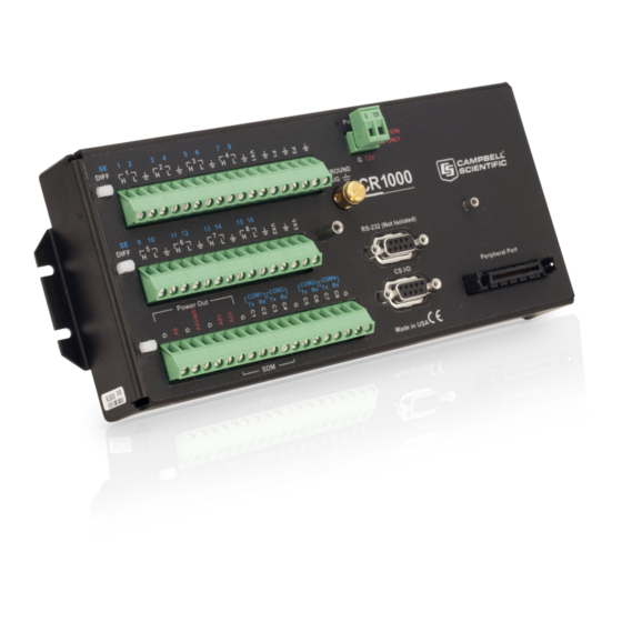
Campbell CR1000 Operator's Manual (588 pages)
Measurement and Control System
Brand:
Campbell
| Category:
Measuring Instruments
| Size: 21 MB
Table of Contents
About this Manual
5
Table of Contents
7
Section 1. Introduction
27
Hello
27
Typography
27
Section 2. Cautionary Statements
29
Section 3. Initial Inspection
31
Section 4. Quickstart Tutorial
33
Primer - CR1000 Data-Acquisition
33
Components of a Data-Acquisition System
33
Data Retrieval
33
Datalogger
33
Sensors
33
CR1000 Module and Power Supply
34
Figure 1: Data-Acquisition System Components
34
Wiring Panel
34
Backup Battery
35
Figure 2: Wiring Panel
35
Power Supply
35
Sensors
36
Analog Sensors
36
Figure 3: Analog Sensor Wired to Single-Ended Channel #1
36
Figure 4: Analog Sensor Wired to Differential Channel #1
36
Bridge Sensors
37
Table 1. Single-Ended and Differential Input Channels
37
Voltage Excitation
37
Figure 5: Half-Bridge Wiring -- Wind Vane Potentiometer
38
Figure 6: Full-Bridge Wiring -- Pressure Transducer
38
Pulse Sensors
38
Figure 7: Pulse-Sensor Output Signal Types
39
Pulse Sensor Wiring
39
Pulse-Input Channels
39
Pulses Measured
39
Table 2. Pulse-Input Channels and Measurements
39
Figure 8: Pulse Input Wiring -- Anemometer Switch
40
RS-232 Sensors
40
Sensors
40
Digital I/O Ports
41
Figure 9: Location of RS-232 Ports
41
Figure 10: Use of RS-232 and Digital I/O When Reading RS-232 Devices
41
SDM Channels
42
Input Expansion Modules
42
List of Tables
37
Hands-On: Measuring a Thermocouple
42
Figure 11: Control and Monitoring with Digital I/O
42
Hardware Setup
43
External Power Supply
43
What You will Need
43
Figure 12: Power and RS-232 Connections
44
PC200W Software Setup
44
Figure 13: PC200W Main Window
45
Table 3. PC200W Ezsetup Wizard Example Selections
45
Write Program with Short Cut
46
Procedure: (Short Cut Steps 1 to 6)
46
Figure 14: Short Cut Temperature Sensor Folder
47
Procedure: (Short Cut Steps 7 to 9)
47
Figure 15: Short Cut Thermocouple Wiring
48
Procedure: (Short Cut Steps 10 to 11)
48
Figure 16: Short Cut Outputs Tab
49
Procedure: (Short Cut Steps 12 to 16)
49
Figure 17: Short Cut Output Table Definition
50
Figure 18: Short Cut Compile Confirmation
50
Procedure: (Short Cut Step 17 to 18)
50
Send Program and Collect Data
51
Figure 19: PC200W Connect Button
51
Procedure: (PC200W Step 1)
51
Procedure: (PC200W Steps 2 to 4)
51
Figure 20: PC200W Monitor Data Tab - Public Table
52
Figure 21: PC200W Monitor Data Tab - Public and Onemin Tables
52
Procedure: (PC200W Step 5)
52
Figure 22: PC200W Collect Data Tab
53
Procedure: (PC200W Step 6)
53
Procedure: (PC200W Steps 7 to 9)
53
Figure 23: PC200W View Data Utility
54
Procedure: (PC200W Steps 10 to 11)
54
Figure 24: PC200W View Data Table
55
Figure 25: PC200W View Line Graph
55
Procedure: (PC200W Steps 12 to 13)
55
Section 5. System Overview
57
CR1000 Datalogger
58
Figure 26: Features of a Data-Acquisition System
58
Clock
59
Sensor Support
59
CR1000 Wiring Panel
60
Measurement Inputs
60
Voltage Outputs
61
Grounding Terminals
62
Power in
62
Power out
62
Power Terminals
62
Communications Ports
63
CR1000KD Keyboard Display
63
Figure 27: CR1000KD Keyboard Display
64
Power Requirements
64
Programming
65
Operating System and Settings
65
User Programming
66
Memory and Final Data Storage
66
Data Retrieval
67
Via Mass-Storage Device
67
Via Telecommunications
67
Data File-Formats in CR1000 Memory
68
Data Format on Computer
68
Via CF Card
68
Communications
68
DNP3 Communication
69
Modbus
69
Pakbus
69
Custom Menus
70
Keyboard Display
70
Security
70
Figure 28: Custom Menu Example
70
Vulnerabilities
71
Pass-Code Lockout
72
Csipasswd
74
IS Instructions
74
Pakbus Instructions
74
Passwords
74
Security By-Pass
74
Communications Encryption
75
File Encryption
75
Hiding Files
75
Settings
75
Signatures
75
Maintenance
76
Calibration
76
Internal Battery
76
Protection from Voltage Transients
76
Protection from Water
76
Datalogger Support Software
77
Section 6. CR1000 Specifications
79
Advertisement
Campbell CR1000 Operator's Manual (678 pages)
Measurement and Control System
Brand:
Campbell
| Category:
Measuring Instruments
| Size: 26 MB
Table of Contents
Control System
1
Table of Contents
9
1 Introduction
33
Hello
33
Typography
33
Capturing Crbasic Code
34
2 Cautionary Statements
37
3 Initial Inspection
39
4 System Quickstart
41
Data-Acquisition Systems - Quickstart
41
Sensors - Quickstart
42
Figure 1. Data-Acquisition System Components
42
Datalogger - Quickstart
43
Wiring Panel - Quickstart
43
Power Supplies - Quickstart
44
Figure 2. Wiring Panel
44
Internal Battery - Quickstart
45
Data Retrieval and Telecommunications - Quickstart
45
Datalogger Support Software - Quickstart
46
Tutorial: Measuring a Thermocouple
46
What You will Need
46
Hardware Setup
47
External Power Supply
47
PC200W Software Setup
48
Figure 3. Power and Serial Communication Connections
48
Figure 4. PC200W Main Window
49
Table 1. PC200W Ezsetup Wizard Example Selections
49
Write Crbasic Program with Short Cut
50
Procedure: (Short Cut Steps 1 to 5)
50
Figure 5. Short Cut Temperature Sensor Folder
51
Procedure: (Short Cut Steps 6 to 7)
51
Figure 6. Short Cut Thermocouple Wiring -- Needs New Image for CR6: 1H = U1, 1L = U2
52
Procedure: (Short Cut Step 8)
52
Figure 7. Short Cut Outputs Tab
53
Procedure: (Short Cut Steps 9 to 12)
53
Figure 8. Short Cut Outputs Tab
54
Procedure: (Short Cut Steps 13 to 14)
54
Send Program and Collect Data
55
Procedure: (PC200W Step 1)
55
Procedure: (PC200W Steps 2 to 4)
55
Procedure: (PC200W Step 5)
56
Procedure: (PC200W Step 6)
57
Procedure: (PC200W Steps 7 to 10)
58
Procedure: (PC200W Steps 11 to 12)
59
Procedure: (PC200W Steps 13 to 14)
59
Figure 16. PC200W View Line Graph
60
5 System Overview
61
Measurements - Overview
62
Time Keeping - Overview
63
Analog Measurements - Overview
63
Voltage Measurements - Overview
63
Figure 18. Analog Sensor Wired to Single-Ended Channel #1
64
Single-Ended Measurements - Overview
65
Table 2. Differential and Single-Ended Input Terminals
65
Current Measurements - Overview
66
Differential Measurements - Overview
66
Resistance Measurements - Overview
67
Voltage Excitation
67
Strain Measurements - Overview
68
Pulse Measurements - Overview
68
Pulse-Input Channels
69
Pulses Measured
69
Table 3. Pulse-Input Terminals and Measurements
69
Pulse Sensor Wiring
70
Period Averaging - Overview
70
Vibrating-Wire Measurements - Overview
71
Reading Smart Sensors - Overview
71
Overview
72
SDI-12 Sensor Support — Overview
72
Sensor Support - Overview
72
Field Calibration - Overview
73
Cabling Effects - Overview
74
Synchronizing Measurements - Overview
74
PLC Control - Overview
74
Datalogger - Overview
75
Time Keeping - Overview
75
Wiring Panel - Overview
76
Table 4. CR1000 Wiring Panel Terminal Definitions
77
Switched Voltage Output - Overview
78
Voltage Excitation - Overview
79
Grounding Terminals
80
Power in
80
Power out Terminals
80
Power Terminals
80
Communication Ports
81
CS I/O Port
81
CPI Port
82
Peripheral Port
82
Ports
82
SDM Port
82
Ethernet Port
83
Keyboard Display - Overview
83
Character Set
83
Custom Menus - Overview
84
Measurement and Control Peripherals - Overview
85
Power Supplies - Overview
85
CR1000 Configuration - Overview
86
Crbasic Programming - Overview
86
Memory - Overview
87
Data Retrieval and Telecommunications - Overview
88
Pakbus® Communications - Overview
88
Mass-Storage Device
89
Memory Card (CRD: Drive) - Overview
89
Telecommunications
89
Data Format on Computer
90
Data-File Formats in CR1000 Memory
90
Alternate Telecommunications - Overview
90
DNP3 - Overview
91
Modbus
91
TCP/IP - Overview
91
Security - Overview
92
Maintenance - Overview
93
Protection from Moisture - Overview
93
Factory Calibration
94
Internal Battery - Details
94
Protection from Voltage Transients
94
Datalogger Support Software - Overview
95
6 Specifications
97
7 Installation
99
Protection from Moisture - Details
99
Temperature Range
99
Enclosures
99
Power Supplies - Details
100
CR1000 Power Requirement
101
Calculating Power Consumption
101
Power Sources
101
Vehicle Power Connections
102
Uninterruptable Power Supply (UPS)
102
External Power Supply Installation
103
Switched Voltage Output - Details
103
Table 5. Current Source and Sink Limits
103
Continuous Regulated (5V Terminal)
104
Continuous Unregulated Voltage (12V Terminal)
104
Switched-Voltage Excitation
104
Switched Unregulated Voltage (SW12 Terminal)
105
Grounding
105
ESD Protection
105
Lightning Protection
107
Single-Ended Measurement Reference
108
Ground-Potential Differences
109
External Signal Conditioner
109
Soil Temperature Thermocouple
109
Ground Looping in Ionic Measurements
109
Figure 35. Model of a Ground Loop with a Resistive Sensor
110
CR1000 Configuration - Details
111
Configuration Tools
111
Configuration with Devconfig
111
Network Planner
112
Overview
113
Basics
114
Configuration with Status/Settings/Dti
114
Configuration with Executable CPU: Files
115
Table 6. Status/Setting/Dti: Access Points
115
Default.cr1 File
116
Executable File Run Priorities
116
CR1000 Configuration - Details
117
Table 7. Common Configuration Actions and Tools
117
Updating the Operating System (OS)
117
OS Update with Devconfig Send os Tab
118
OS Update with Devconfig
119
OS Update with Devconfig
121
Restoring Factory Defaults
122
Saving and Restoring Configurations
122
Crbasic Programming - Details
122
Program Structure
123
Table 8. Crbasic Program Structure
123
Writing and Editing Programs
125
Crbasic Editor
125
Short Cut Programming Wizard
125
Conserving Program Memory
126
Inserting Comments into Program
126
Sending Crbasic Programs
126
Preserving Data at Program Send
127
Table 9. Program Send Options that Reset Memory
127
Programming Syntax
128
Multiple Statements on One Line
128
One Statement on Multiple Lines
128
Program Statements
128
Table 10. Data Table Structures
128
Declaring Variables
129
Single-Statement Declarations
129
Declaring Data Types
130
Table 11. Data Types in Variable Memory
130
Table 12. Data Types in Final-Data Memory
131
Dimensioning Numeric Variables
134
Dimensioning String Variables
134
Declaring Arrays
135
Declaring Flag Variables
135
Declaring Local and Global Variables
136
Declaring Constants
137
Initializing Variables
137
Declaring Aliases and Units
138
Predefined Constants
138
Numerical Formats
139
Table 13. Formats for Entering Numbers in Crbasic
139
Declaring Data Tables
140
Multi-Statement Declarations
140
Table 14. Typical Data Table
141
Table 15. TOA5 Environment Line
141
Table 16. Datainterval() Lapse Parameter Options
145
Declaring Subroutines
147
Include' File
147
Figure 40. "Include File" Settings Via Devconfig
149
Declaring Incidental Sequences
150
Declaring Subroutines
150
Execution and Task Priority
151
Pipeline Mode
152
Table 17. Program Tasks
152
Sequential Mode
153
Table 18. Pipeline Mode Task Priorities
153
Execution Timing
154
Scan() / Nextscan
154
Table 19. Program Timing Instructions
154
Slowsequence / Endsequence
155
Scan Priorities in Sequential Mode
156
Subscan() / Nextsubscan
156
Measurement and Data-Storage Processing
158
Programming Instructions
158
Argument Types
159
Names in Arguments
159
Table 20. Rules for Names
159
Expressions in Arguments
160
Programming Expression Types
160
Floating-Point Arithmetic
161
Mathematical Operations
161
Expressions with Numeric Data Types
162
Logical Expressions
164
Table 21. Binary Conditions of TRUE and FALSE
165
Table 22. Logical Expression Examples
165
String Expressions
166
Programming Access to Data Tables
167
Table 23. Data Process Abbreviations
168
Programming to Use Signatures
169
Programming Resource Library
169
Advanced Programming Techniques
169
Capturing Events
169
Conditional Output
170
Groundwater Pump Test
171
Miscellaneous Features
174
Pulsecountreset Instruction
177
Scaling Array
177
Binary Runtime Signature
178
Executable Code Signatures
178
Signatures: Example Programs
178
Text Signature
178
Use of Multiple Scans
179
Compiling: Conditional Code
180
Displaying Data: Custom Menus - Details
182
Figure 43. Custom Menu Example — Home Screen
183
Figure 45. Custom Menu Example — Make Notes Sub Menu
184
Figure 49. Custom Menu Example — Control Sub Menu
185
Data Input: Loading Large Data Sets
188
Data Input: Array-Assigned Expression
188
Table 24. Crbasic Example. Array Assigned Expression: Sum Columns and Rows
190
Table 26. Crbasic Example. Array Assigned Expression: Comparison Boolean Evaluation
191
Data Output: Calculating Running Average
192
Figure 52. Running-Average Frequency Response
194
Data Output: Triggers and Omitting Samples
195
Figure 54. Data from Trigvar Program
196
Data Output: Two Intervals in One Data Table
197
Data Output: Using Data Type Bool8
198
Figure 55. Alarms Toggled in Bit-Shift Example
199
Figure 57. Bool8 Data from Bit-Shift Example (PC Data File)
200
Data Output: Using Data Type NSEC
202
NSEC Options
202
Data Output: Writing High-Frequency Data to Memory Cards
205
Tablefile() with Option 64
206
Tablefile() with Option 64 Replaces Cardout()
206
Converting TOB3 Files with Cardconvert
207
Tablefile() with Option 64 Programming
207
Tablefile() with Option 64 Q & a
208
Field Calibration - Details
210
Field Calibration CAL Files
210
Field Calibration Numeric Monitor Procedures
211
Field Calibration Programming
211
Field Calibration Wizard Overview
211
One-Point Calibrations (Zero or Offset)
212
Field Calibration Examples
213
Two-Point Calibrations (Gain and Offset)
213
Zero Basis Point Calibration
213
Fieldcal() Zero or Tare (Opt 0) Example
214
Fieldcal() Offset (Opt 1) Example
216
Fieldcal() Slope and Offset (Opt 2) Example
218
Fieldcal() Slope (Opt 3) Example
220
Table 32. Calibration Report for Water Content Sensor
221
Field Calibration Strain Examples
223
Fieldcal() Zero Basis (Opt 4) Example -- 8
223
Field Calibration Strain Examples
224
Figure 58. Quarter-Bridge Strain-Gage with RC Resistor Shunt
225
Fieldcalstrain() Quarter-Bridge Shunt Example
226
Fieldcalstrain() Quarter-Bridge Zero
227
Measurement: Excite, Delay, Measure
228
Measurement: Faster Analog Rates
229
Measurements from 1 to 100 Hz
230
Measurement Rate: 101 to 600 Hz
231
Measurements from 101 to 600 Hz 2
232
Measurement Rate: 601 to 2000 Hz
233
Measurement: PRT
234
Measuring Pt100S (100 Ω Prts)
235
PRT Calculation Standards
235
Self-Heating and Resolution
235
Table 35. Prtcalc() Type-Code-1 Sensor
236
Table 36. Prtcalc() Type-Code-2 Sensor
237
PT100 in Four-Wire Half-Bridge
238
Calculating the Brhalf4W() Multiplier
239
Calculating the Excitation Voltage
239
Choosing Rf
240
PT100 in Three-Wire Half Bridge
241
PT100 in Four-Wire Full-Bridge
242
PLC Control - Details
244
Serial I/O: Capturing Serial Data
245
Introduction
245
I/O Ports
246
Glossary of Serial I/O Terms
247
Protocols
247
Serial I/O Crbasic Programming
249
Serial I/O Programming Basics
250
Serial I/O Input Programming Basics
251
Serial I/O Output Programming Basics
252
Serial I/O Memory Considerations
253
Serial I/O Translating Bytes
253
Demonstration Program
254
Configure Hyperterminal
256
Serial I/O Application Testing
256
Figure 67. Hyperterminal Connect-To Settings
257
Create Send-Text File
258
Create Text-Capture File
258
Serial I/O Example II
259
Serial I/O Q & a
264
Serial I/O: SDI-12 Sensor Support - Programming Resource
267
Transparent Mode
267
Transparent Mode Commands
268
Table 43. SDI-12 Commands for Transparent Mode
269
Recorder Mode
272
Sensor Mode
279
Power Considerations
281
String Operations
282
String Operators
282
String Concatenation
283
Table 47. String Concatenation Examples
284
String NULL Character
285
Extracting String Characters
286
Inserting String Characters
286
Formatting Strings
287
String Use of ASCII / ANSII Codes
287
Formatting String Hexadecimal Variables
288
Subroutines
288
TCP/IP - Details
289
Pakbus over TCP/IP and Callback
290
Custom HTTP Web Server
291
Default HTTP Web Server
291
Figure 74. Home Page Created Using Webpagebegin() Instruction
292
Figure 75. Customized Numeric-Monitor Web
293
FTP Client
294
FTP Server
294
Dhcp
295
Micro-Serial Server
295
Modbus TCP/IP
295
Ping (IP)
295
Snmp
295
Telnet
295
Dns
296
Smtp
296
Wind Vector
296
Outputopt Parameters
296
Wind Vector Processing
297
Calculations
298
Measured Raw Data
298
Figure 77. Mean Wind-Vector Graph
299
Figure 78. Standard Deviation of Direction
300
Campbell CR1000 Operator's Manual (628 pages)
Brand:
Campbell
| Category:
Data Loggers
| Size: 23 MB
Table of Contents
Table of Contents
9
1 Introduction
29
Hello
29
Typography
30
Capturing Crbasic Code
30
2 Precautions
31
3 Initial Inspection
33
4 Quickstart
35
Sensors - Quickstart
35
Datalogger - Quickstart
36
CR1000 Module
36
Wiring Panel - Quickstart
36
Power Supplies - Quickstart
37
Internal Battery - Quickstart
38
Data Retrieval and Comms - Quickstart
38
Datalogger Support Software - Quickstart
39
Datalogger Support Software - List
39
Tutorial: Measuring a Thermocouple
40
What You will Need
40
Hardware Setup
40
Connect Comms
41
Connect External Power Supply
41
FIGURE 2: Connect Power and Comms
41
PC200W Software Setup
42
FIGURE 3: PC200W Main Window
42
Write Crbasic Program with Short Cut
43
PC200W Ezsetup Wizard Prompts
43
Procedure: (Short Cut Steps 1 to 5)
44
FIGURE 4: Short Cut Temperature Sensor Folder
44
Procedure: (Short Cut Steps 6 to 7)
45
Procedure: (Short Cut Step 8)
45
Procedure: (Short Cut Steps 9 to 12)
45
FIGURE 5: Short Cut Outputs Tab
45
Procedure: (Short Cut Steps 13 to 14)
46
Send Program and Collect Data
46
FIGURE 6: Short Cut Compile Confirmation Window and Results Tab
46
FIGURE 7: PC200W Main Window
47
Procedure: (PC200W Step 1)
47
Procedure: (PC200W Steps 2 to 4)
47
FIGURE 8: PC200W Monitor Data Tab - Public Table
48
Procedure: (PC200W Step 5)
48
FIGURE 10: PC200W Collect Data Tab
49
FIGURE 9: PC200W Monitor Data Tab - Public and Onemin Tables
49
Procedure: (PC200W Step 6)
49
FIGURE 11: PC200W View Data Utility
50
Procedure: (PC200W Steps 7 to 10)
50
FIGURE 12: PC200W View Data Table
51
Procedure: (PC200W Steps 11 to 12)
51
Procedure: (PC200W Steps 13 to 14)
51
Data Acquisition Systems - Quickstart
52
FIGURE 13: PC200W View Line Graph
52
FIGURE 14: Data Acquisition System Components
53
5 Overview
55
Datalogger - Overview
56
FIGURE 15: Data Acquisition System - Overview
56
Wiring Panel - Overview
57
FIGURE 16: Wiring Panel
58
FIGURE 1: Wiring Panel
58
CR1000 Wiring Panel Terminal Definitions
58
Switched Voltage Output - Overview
60
Voltage Excitation - Overview
60
FIGURE 17: Control and Monitoring with C Terminals
60
Power Terminals
61
Power in Terminals
61
Power out Terminals
61
Communication Ports - Overview
62
CS I/O Port
63
Peripheral Port
63
Ports
63
CPI Port and CDM Devices - Overview
64
Ethernet Port
64
Grounding - Overview
64
Ports
64
SDM Port
64
Measurements - Overview
65
Time Keeping - Overview
65
Analog Measurements - Overview
66
Voltage Measurements - Overview
66
FIGURE 18: Analog Sensor Wired to Single-Ended Channel #1
67
FIGURE 19: Analog Sensor Wired to Differential Channel #1
67
Single-Ended Measurements - Overview
68
Current Measurements - Overview
69
Differential Measurements - Overview
69
FIGURE 20: Half-Bridge Wiring Example - Wind Vane Potentiometer
70
Resistance Measurements - Overview
70
Voltage Excitation
70
FIGURE 21: Full-Bridge Wiring Example - Pressure Transducer
71
Pulse Measurements - Overview
71
Strain Measurements - Overview
71
FIGURE 22: Pulse Sensor Output Signal Types
72
Pulse Input Channels
72
Pulses Measured
72
FIGURE 23: Pulse Input Wiring Example - Anemometer
73
Pulse Sensor Wiring
73
Pulse Input Terminals and Measurements
73
Period Averaging - Overview
74
Vibrating Wire Measurements - Overview
74
Reading Smart Sensors - Overview
75
Sensor Support - Overview
75
FIGURE 24: Terminals Configurable for RS-232 Input
76
FIGURE 25: Use of RS-232 and Digital I/O When Reading
76
Overview
76
RS-232 — Overview
76
Cabling Effects - Overview
77
Field Calibration - Overview
77
Synchronizing Measurements - Overview
77
Synchronizing Measurements in a Datalogger Network - Overview
77
Synchronizing Measurements in the CR1000 - Overview
77
Data Retrieval and Comms - Overview
77
Data File Formats in CR1000 Memory
78
Data Format on Computer
78
Mass-Storage Device
78
Memory Card (CRD: Drive) - Overview
78
Comms
79
Comms Protocols
79
Direct with Adapter to PC
79
Pakbus Comms - Overview
79
Alternate Comms Protocols - Overview
80
DNP3 - Overview
81
Modbus - Overview
81
TCP/IP - Overview
81
Comms Hardware - Overview
82
Keyboard/Display - Overview
82
Character Set
83
Custom Menus - Overview
83
FIGURE 26: CR1000KD Keyboard/Display
83
Measurement and Control Peripherals - Overview
84
Power Supplies - Overview
85
CR1000 Setup - Overview
85
Crbasic Programming - Overview
85
Security - Overview
86
Maintenance - Overview
87
Protection from Moisture - Overview
87
Protection from Voltage Transients - Overview
87
Factory Calibration - Overview
88
Internal Battery - Overview
88
Datalogger Support Software - Overview
88
Datalogger Support Software - List
88
PLC Control - Overview
89
Auto Self-Calibration - Overview
91
Memory - Overview
91
6 Specifications
93
Advertisement
Campbell CR1000 Operator's Manual (390 pages)
Measurement and Control System
Brand:
Campbell
| Category:
Control Systems
| Size: 7 MB
Table of Contents
Table of Contents
3
Introduction
19
Quickstart Tutorial
21
CR1000 Mounting
22
Analog Sensors
24
Bridge Sensors
26
Pulse Sensors
27
RS-232 Sensors
28
Hands-On Exercise – Measuring a Thermocouple
29
Programming with Short Cut
30
Connecting to the Datalogger
35
Synchronizing the Clocks
36
Viewing Data
37
PC200W View Data Utility
38
CR1000 Overview
39
Sensor Support
40
Power Requirements
44
Memory and Data Storage
45
Communications
46
CR1000KD Custom Menu Example
47
Security
48
Protection from Voltage Transients
49
Specifications
51
Powering Sensors
53
Switched Unregulated (Nominal 12 Volt)
54
Electronic "Noise": Voltdiff() or Voltse()?
55
Measurement Sequence
56
Analog Voltage Input Ranges with Options for Open Input Detect (OID) and Pull into Common Mode (PCM)
57
Offset Voltage Compensation
58
Input and Excitation Reversal (Revdiff, Revex = True)
59
Ground Reference Offset Voltage (Measoff = True)
60
Integration
61
Full and ½ Cycle Integration Methods for AC Power Line Noise Rejection
62
Signal Settling Time
63
Minimizing Settling Errors
64
CRBASIC Code: Measuring Settling Time
65
Self-Calibration
66
Values Generated by the Calibrate () Instruction
68
Bridge Resistance Measurements
69
Circuits Used with Bridge Measurement Instructions
71
Strain Calculations
72
Strain Equations
73
Thermocouple Measurements
74
Panel Temperature
75
Panel Temperature Gradients During -55 to 80°C Change
76
Thermocouple Limits of Error
77
Accuracy of Thermocouple Voltage Measurement
78
Noise on Voltage Measurement
79
Reference Junction Compensation: Temperature to Voltage
80
Error Summary
81
Pulse Count Measurement
82
Pulse Input Channels P1 and P2
83
High-Frequency Pulse
84
Low-Level AC
85
Period Averaging Measurements
86
SDI-12 Recording
87
Field Calibration of Linear Sensor
88
Measurement and Control Peripherals
89
Binary Control
90
Analog Control / Output Devices
91
Vibrating Wire
92
CR1000 Power Supply
93
Battery Connection
94
Grounding
95
Schematic of CR1000 Grounds
96
Lightning Protection
97
Common Mode Range
98
Single-Ended Measurement Reference
99
Soil Temperature Thermocouple
100
CR1000 Configuration
103
Sending the Operating System
104
Devconfig os Download Window for CR1000
105
Sending os to Remote CR1000
106
Devconfig Settings Editor
107
Summary of CR1000 Configuration
108
Deployment Tab
109
Devconfig Deployment | Ports Settings Tab
110
Devconfig Deployment | Advanced Tab
111
Logger Control Tab
112
Settings under Program Control
113
Durable Settings
114
CR1000 "Include File" Settings Via Devconfig
115
Default.cr1 File
116
Inserting Comments into Program
119
CRBASIC Editor
120
Formats for Entering Numbers in CRBASIC
121
Structure
122
CRBASIC Code: Proper Program Structure
123
Declarations
124
Dimensions
125
CRBASIC Code: Data Type Declarations
126
Data Type Operational Detail
127
FP2 Decimal Location
128
Constants
129
Predefined Constants
130
Flags
131
Typical Data Table
132
Data Table Programming
133
Advertisement
Related Products
Campbell CR10XTCR
Campbell CR10X
Campbell CR9000X
Campbell CR7
Campbell CR9000
Campbell CR23X
Campbell CRS456
Campbell CRS451
Campbell CR800 Series
Campbell CR850
Campbell Categories
Measuring Instruments
Accessories
Modem
Weather Station
Recording Equipment
More Campbell Manuals
Login
Sign In
OR
Sign in with Facebook
Sign in with Google
Upload manual
Upload from disk
Upload from URL