
Related Manuals for Juniper EX9208


Summary of Contents for Juniper EX9208
- Page 1 EX9208 Switch Hardware Guide Modified: 2017-01-04 Copyright © 2017, Juniper Networks, Inc.
- Page 2 END USER LICENSE AGREEMENT The Juniper Networks product that is the subject of this technical documentation consists of (or is intended for use with) Juniper Networks software. Use of such software is subject to the terms and conditions of the End User License Agreement (“EULA”) posted at http://www.juniper.net/support/eula.html.
-
Page 3: Table Of Contents
EX9208 Switch Hardware Overview ........ - Page 4 AC Power Supply in an EX9208 Switch ....... . .
- Page 5 Preparation Overview ..........79 Site Preparation Checklist for an EX9208 Switch ......79 Environmental Requirements and Specifications for EX Series Switches .
- Page 6 Connecting Earth Ground to an EX Series Switch ..... 178 Connecting AC Power to an EX9208 Switch ......179 Powering On an AC-Powered EX9200 Switch .
- Page 7 Removing an AC Power Supply from an EX9208 Switch ....217 Installing a DC Power Supply in an EX9208 Switch ..... . . 218 Removing a DC Power Supply from an EX9208 Switch .
- Page 8 Replacing Cable Management Bracket ......267 Installing Cable Management Brackets on an EX9208 Switch ....267 Removing Cable Management Brackets from an EX9208 Switch .
- Page 9 TN Power Warning ..........365 Copyright © 2017, Juniper Networks, Inc.
- Page 10 Nonregulatory Environmental Standards ......371 Compliance Statements for Acoustic Noise for EX Series Switches ..372 Copyright © 2017, Juniper Networks, Inc.
- Page 11 Figure 12: Midplane in an EX9208 Switch ....... . 26...
- Page 12 EX9208 Switch Chassis ........
- Page 13 Replacing Cooling System Component ......209 Figure 61: Installing a Fan Tray in an EX9208 Switch ..... . 210 Figure 62: Installing the Upper Fan Tray in an EX9214 Switch .
- Page 14 Components ........... . . 281 Figure 94: Location of the Serial Number ID Label on EX9208 Switch Chassis . . 285 Figure 95: Location of the Serial Number ID Label on an AC Power Supply .
- Page 15 Switch Overview ........... 3 Table 3: Line Cards Available for EX9208 Switches ......5 Table 4: Power Supplies Supported on EX9208 Switches .
- Page 16 Table 43: AC Power System Specifications ......93 Table 44: AC Power Cord Specifications for an EX9208 Switch ....93 Table 45: DC Power Supply Specifications for an EX9208 Switch .
- Page 17 Unpacking the Switch ..........155 Table 63: Parts List for Different EX9208 Switch Configurations ... . . 158 Table 64: Accessory Box Parts List .
- Page 18 EX9208 Switch Hardware Guide xviii Copyright © 2017, Juniper Networks, Inc.
-
Page 19: About The Documentation
® To obtain the most current version of all Juniper Networks technical documentation, see the product documentation page on the Juniper Networks website at http://www.juniper.net/techpubs/ If the information in the latest release notes differs from the information in the documentation, follow the product Release Notes. -
Page 20: Table 1: Notice Icons
RFC 1997, BGP Communities Attribute Italic text like this Represents variables (options for which Configure the machine’s domain name: you substitute a value) in commands or [edit] configuration statements. root@# set system domain-name domain-name Copyright © 2017, Juniper Networks, Inc. -
Page 21: Documentation Feedback
We encourage you to provide feedback, comments, and suggestions so that we can improve the documentation. You can provide feedback by using either of the following methods: Online feedback rating system—On any page of the Juniper Networks TechLibrary site , simply click the stars to rate the content, http://www.juniper.net/techpubs/index.html and use the pop-up form to provide us with information about your experience. -
Page 22: Requesting Technical Support
7 days a week, 365 days a year. Self-Help Online Tools and Resources For quick and easy problem resolution, Juniper Networks has designed an online self-service portal called the Customer Support Center (CSC) that provides you with the following features: Find CSC offerings: http://www.juniper.net/customers/support/... - Page 23 About the Documentation For international or direct-dial options in countries without toll-free numbers, see http://www.juniper.net/support/requesting-support.html Copyright © 2017, Juniper Networks, Inc. xxiii...
- Page 24 EX9208 Switch Hardware Guide xxiv Copyright © 2017, Juniper Networks, Inc.
-
Page 25: Overview
PART 1 Overview Switch Overview on page 3 Chassis Components and Descriptions on page 13 Cooling System and Airflow on page 39 Power Supplies on page 43 Line Cards on page 51 Copyright © 2017, Juniper Networks, Inc. - Page 26 EX9208 Switch Hardware Guide Copyright © 2017, Juniper Networks, Inc.
-
Page 27: Switch Overview
Layer 3 switching, routing, and security services. Chassis Physical Specifications The EX9208 switch is eight rack units (8 U) in size. Five EX9208 switches can fit in a standard 48 U rack. Each EX9208 switch is designed to optimize rack space and cabling. -
Page 28: Figure 1: Front View Of An Ex9208 Switch
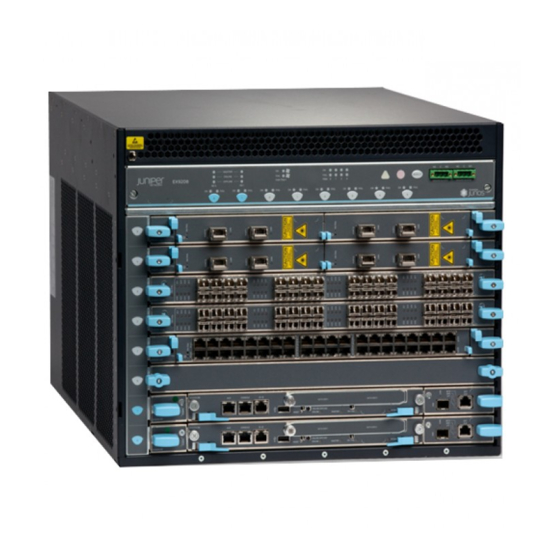
EX9208 Switch Hardware Guide Figure 1: Front View of an EX9208 Switch Craft interface panel Front-mounting flange ESD point Line cards Air intake Figure 2: Rear View of an EX9208 Switch with AC Power Supplies Copyright © 2017, Juniper Networks, Inc. -
Page 29: Host Subsystem
“EX9208 Switch Configurations” on page Line Cards The EX9208 switch has six horizontal line card slots and supports line rate for each line card. The line cards in EX9208 switches combine a Packet Forwarding Engine and Ethernet interfaces in a single assembly. Line cards are field-replaceable units (FRUs) that you can install in the line card slots—labeled... -
Page 30: Cooling System
(SFP+) transceivers Cooling System The cooling system in an EX9208 switch is a field-replaceable unit (FRU). It consists of a hot-removable and hot-insertable fan tray. The fan tray contains six fans. The fan tray installs vertically on the right back of the chassis and provides side-to-side chassis cooling. -
Page 31: Ex9208 Switch Configurations
A base-configuration EX9208 switch ships with three low-line (100–120 VAC) or two high-line (200–240 VAC) AC power supplies. An AC-powered, redundant-configuration EX9208 switch ships with four low-line (100–120 VAC) or four high-line (200–240 VAC) AC power supplies. See “AC Power Supply in an EX9208 Switch” on page A DC-powered, redundant-configuration EX9208 switch ships with four DC power supplies. - Page 32 EX9208 Switch Hardware Guide Table 5: EX9208 Switch Hardware Configurations (continued) Switch Configuration Configuration Components EX9208-BASE3A-AC Chassis with front-panel display (craft interface) and (base configuration with 2520 W AC power supplies) midplane One Switch Fabric 2 module (SF2 module) One Routing Engine module (RE module)
-
Page 33: Ex9208 Switch Hardware And Cli Terminology Mapping
EX9208 Switch Hardware Overview on page 3 EX9208 Switch Hardware and CLI Terminology Mapping This topic describes the hardware terms used in EX9208 switch documentation and the corresponding terms used in the Junos OS CLI. See Table 6 on page... - Page 34 EX9208 Switch Hardware Guide Table 6: CLI Equivalents of Terms Used in Documentation for EX9208 Switches (continued) Hardware Item in Additional Item (CLI) Description (CLI) Value (CLI) Documentation Information PEM(n) One of the following: n is a value in the range of...
- Page 35 Chapter 1: Switch Overview Table 6: CLI Equivalents of Terms Used in Documentation for EX9208 Switches (continued) Hardware Item in Additional Item (CLI) Description (CLI) Value (CLI) Documentation Information MIC (n) Abbreviated name of the n is a value in the range of...
- Page 36 EX9208 Switch Hardware Guide Copyright © 2017, Juniper Networks, Inc.
-
Page 37: Chassis Components And Descriptions
Switch Fabric Module LEDs in an EX9200 Switch on page 35 Cable Management Brackets in an EX9208 Switch on page 36 Chassis Physical Specifications of an EX9208 Switch The EX9208 switch chassis is a rigid sheet-metal structure that houses the other switch components. Table 7 on page 13 summarizes the physical specifications of the EX9208 switch chassis. - Page 38 EX9208 Switch Hardware Guide Table 7: Physical Specifications of the EX9208 Switch Chassis (continued) Description Weight Height Width Depth Routing Engine 2.4 lb (1.9 kg) 1.25 in. (3.2 cm) 11 in. (27.9 cm) 7.75 in. (19.7 cm) module (RE module) Switch Fabric 9.6 lb (4.4 kg) (with...
-
Page 39: Figure 4: Ex9208 Switch
Chapter 2: Chassis Components and Descriptions Table 7: Physical Specifications of the EX9208 Switch Chassis (continued) Description Weight Height Width Depth EX9200-40F-M line 14.8 lb (6.7 kg) 1.25 in. (3.2 cm) 17 in. (43.2 cm) 22 in. (55.9 cm) card EX9200-40XS line 17 lb (7.7 kg) -
Page 40: Field-Replaceable Units In An Ex9200 Switch
EX9208 Switch Hardware Guide Figure 6: EX9208 Switch with DC Power Supplies You can mount an EX9208 switch on a standard 19-in. four-post rack or a standard 800-mm enclosed cabinet. You can mount up to six EX9208 switches in a standard (48 rack unit (U)) rack. - Page 41 “Pluggable Transceivers Supported on EX9200 Switches” on page 103 for the Junos OS release in which the transceivers were introduced. NOTE: Line cards are not part of the base or redundant configuration. You must order them separately. Copyright © 2017, Juniper Networks, Inc.
-
Page 42: Understanding Ex9208 Switch Component And Functionality Redundancy
Understanding EX9208 Switch Component and Functionality Redundancy The Juniper Networks EX9208 Ethernet Switches are available as fully redundant system. A redundant EX9208 switch configuration is designed so that no single point of failure can cause the entire switch to fail. See “EX9208 Switch Configurations”... -
Page 43: Craft Interface In An Ex9200 Switch
“DC Power Supply in an EX9208 Switch” on page Cooling system—The cooling system in EX9208 switches consists of fan tray and air filter. The fan tray contains six fans. Under normal operating conditions, the fans in the fan tray run at less than full speed. If one of the fans fails, the host subsystem increases the speed of the remaining fans to provide sufficient cooling for the switch indefinitely. -
Page 44: Figure 7: Craft Interface In An Ex9204 Switch
You can install a line card or an SF module in the multifunctional slot labeled in EX9204 switches. The corresponding LED displays information depending on the hardware installed in that slot. Figure 8: Craft Interface in an EX9208 Switch 1— Host subsystem LEDs 6—... -
Page 45: Host Subsystem Leds
The LEDs grouped with labels show the status of the host subsystems installed in the switch. Table 9 on page 22 describes the functions of these LEDs. Copyright © 2017, Juniper Networks, Inc. -
Page 46: Fan Leds
LEDs on the craft interface. Table 11: Power Supply LEDs on the Craft Interface Label Status Description Green Power supply is functioning normally. Power supply in not installed. Copyright © 2017, Juniper Networks, Inc. -
Page 47: Switch Fabric Leds And Control Buttons
LEDs. Table 13: Line Card LEDs on the Craft Interface Label Status Description Green On steadily—Line card is functioning normally. Blinking—Line card is coming online or going offline. Unlit Line card is not online. Copyright © 2017, Juniper Networks, Inc. -
Page 48: Alarm Leds And Alarm Cutoff Button
Whenever a system condition triggers either the critical (major alarm) or warning (minor alarm) alarm on the craft interface, the alarm relay contacts are also activated. The alarm relay contacts are located on the upper right of the craft interface. Copyright © 2017, Juniper Networks, Inc. -
Page 49: Midplane In An Ex9200 Switch
Craft Interface panel Related EX9204 Switch Hardware Overview Documentation EX9208 Switch Hardware Overview on page 3 EX9214 Switch Hardware Overview Chassis Component Alarm Conditions on EX9200 Switches on page 302 Midplane in an EX9200 Switch The midplane is located on the rear of the chassis and forms the rear of the card cage. -
Page 50: Figure 11: Midplane In An Ex9204 Switch
EX9208 Switch Hardware Guide Figure 11: Midplane in an EX9204 Switch Midplane Figure 12: Midplane in an EX9208 Switch Midplane Copyright © 2017, Juniper Networks, Inc. -
Page 51: Routing Engine Module In An Ex9200 Switch
Routing Engine modules (RE modules) are installed directly into Switch Fabric modules (SF modules). Each RE module houses one Routing Engine. An EX9204 or EX9208 switch can have either one or two Routing Engines. An EX9214 switch can have either two or three Routing Engines. -
Page 52: Figure 14: Re Module In An Ex9200 Switch
Engine is hot-pluggable. If only one RE module is installed, you must disable the switch before removing the RE module. A base configuration EX9204 and EX9208 switch has only one RE module. See EX9204 Switch Configurations and “EX9208 Switch Configurations” on page 7. -
Page 53: Switch Fabric Module In An Ex9200 Switch
Switch Fabric modules (SF modules) are installed horizontally on the front panel of the switch chassis. You can install either one or two SF modules in an EX9204 or EX9208 switch and either two or three SF modules in an EX9214 switch. A base configuration EX9204 or EX9208 switch has only one SF module, and a base configuration EX9214 switch has two SF modules. -
Page 54: Figure 15: Sf Module Ex9200-Sf
EX9208 Switch Hardware Guide In EX9204 and EX9208 switches, you can add a second SF module to the configuration for host subsystem redundancy. In EX9214 switches, you can add a third SF module to the configuration for host subsystem redundancy. If two SF modules are installed, one SF module functions as the master and the other functions as the backup. -
Page 55: Figure 16: Sf Module Ex9200-Sf2
The SF modules install horizontally into the front of the chassis. If any slots are empty, you must install a cover panel. The SF module has the following components: Chassis management Ethernet switch I2C bus logic, used for low-level communication with each component Copyright © 2017, Juniper Networks, Inc. -
Page 56: Host Subsystem In An Ex9200 Switch
You can install either one or two host subsystems in the front panel of an EX9204 or an EX9208 switch. A base configuration EX9204 and EX9208 switch has one host subsystem. A redundant configuration EX9204 and EX9208 switch has a second host subsystem. -
Page 57: Network Port Leds On Line Cards In An Ex9200 Switch
Chapter 2: Chassis Components and Descriptions NOTE: In EX9204 and EX9208 switches, we recommend that you install two host subsystems for redundant protection. If you install only one host subsystem, we recommend that you install it in slot . In EX9214 switches, we recommend that you install three host subsystems for redundant protection. -
Page 58: Modular Interface Card Led In An Ex9200 Switch
EX9200-40F-M Line Card on page 68 EX9200-40T Line Card on page 65 Table 17 on page 35 describes the MIC LED on line cards for EX9200 switches, its colors and state, and the status it indicates. Copyright © 2017, Juniper Networks, Inc. -
Page 59: Routing Engine Module Leds In An Ex9200 Switch
On steadily—The MIC has failed. Related EX9204 Switch Hardware Overview Documentation EX9208 Switch Hardware Overview on page 3 EX9214 Switch Hardware Overview Routing Engine Module LEDs in an EX9200 Switch Each Routing Engine module (RE module) has four LEDs on the module faceplate. -
Page 60: Cable Management Brackets In An Ex9208 Switch
Documentation Removing an SF Module from an EX9200 Switch on page 235 Taking the Host Subsystem Offline in an EX9200 Switch on page 226 Cable Management Brackets in an EX9208 Switch The cable management brackets (see Figure 17 on page... -
Page 61: Figure 18: Cable Management Brackets Installed On The Switch
Figure 18: Cable Management Brackets Installed on the Switch Cable managers Related Installing Cable Management Brackets on an EX9208 Switch on page 267 Documentation Removing Cable Management Brackets from an EX9208 Switch on page 268 Copyright © 2017, Juniper Networks, Inc. - Page 62 EX9208 Switch Hardware Guide Copyright © 2017, Juniper Networks, Inc.
-
Page 63: Cooling System And Airflow
Cooling System and Airflow in an EX9208 Switch on page 39 Cooling System and Airflow in an EX9208 Switch The cooling system in an EX9208 switch consists of a fan tray and an air filter. The cooling system components work together to keep all switch components within the acceptable temperature range. -
Page 64: Airflow Direction In The Ex9208 Switch Chassis
EX9208 Switch Hardware Guide Figure 19: Fan Tray for an EX9208 Switch Figure 20: Air Filter for an EX9208 Switch Airflow Direction in the EX9208 Switch Chassis The air intake to cool the chassis is located on the side of the chassis next to the air filter. -
Page 65: Figure 21: Airflow Through The Ex9208 Switch Chassis
Chapter 3: Cooling System and Airflow Figure 21: Airflow Through the EX9208 Switch Chassis Front view Side view Rear view Airflow (front boards) Airflow (power supplies) Airflow (front boards) Air intake intake Power supply exhaust Front Rear Card cage Card cage... - Page 66 EX9208 Switch Hardware Guide Copyright © 2017, Juniper Networks, Inc.
-
Page 67: Power Supplies
The AC power supplies in EX9208 switches are hot-insertable and hot-removable field-replaceable units (FRUs). You can install up to four AC power supplies in an EX9208 switch. Power supplies are installed in the rear of the chassis in slots through (left to right). -
Page 68: Ac Power Supply Configurations
Each power supply has its own fan and is cooled by its own internal cooling system. EX9208 switches support 2520 W AC power supply. The AC power supply supports both the low-voltage line (100–120 VAC) and the high-voltage line (200–240 VAC) AC power configurations. -
Page 69: Ac Power Supply Leds In An Ex9208 Switch
Chapter 4: Power Supplies In the low-line (100–120 V) AC power configuration, the EX9208 switch contains three or four AC power supplies, located horizontally at the rear of the chassis in slots PEM0 through (left to right). Each AC power supply provides power to all components PEM3 in the switch. -
Page 70: Dc Power Supply In An Ex9208 Switch
Power Requirements for EX9200 Switch Components on page 91 DC Power Supply in an EX9208 Switch An EX9208 switch is configurable with two or four DC power supplies. The power supplies connect to the midplane, which distributes the different output voltages produced by the power supplies to the switch components, depending on their voltage requirements. -
Page 71: Dc Power Supply Description
The DC power supplies in EX9000 switches are hot-insertable and hot-removable field-replaceable units (FRUs). You can install either two or four DC power supplies in an EX9208 switch. Power supplies are installed in the rear of the chassis in slots through (left to right). -
Page 72: Dc Power Supply Leds In An Ex9208 Switch
DC Power Supply LEDs in an EX9208 Switch on page 48 Power Requirements for EX9200 Switch Components on page 91 Installing a DC Power Supply in an EX9208 Switch on page 218 Removing a DC Power Supply from an EX9208 Switch on page 220... -
Page 73: Table 22: Dc Power Supply Leds In Ex9208 Switches
DC input to the power supply is not present. Related DC Power Supply in an EX9208 Switch on page 46 Documentation Power Requirements for EX9200 Switch Components on page 91 Copyright © 2017, Juniper Networks, Inc. - Page 74 EX9208 Switch Hardware Guide Copyright © 2017, Juniper Networks, Inc.
-
Page 75: Line Cards
Junos OS release in which the line card was first supported and the Switch Fabric module (SF module) that must be installed in the switch to support each line card. Copyright © 2017, Juniper Networks, Inc. -
Page 76: Table 23: Line Card Models For Ex9200 Switches
MICs: EX9200-10XS-MIC EX9200-20F-MIC EX9200-40T-MIC “EX9200-MPC Line Card” on page 58 EX9200-12QS A line card with six 40-Gigabit 16.1R1 EX9200-SF2 Ethernet rate-selectable ports, each of which can house transceivers “EX9200-12QS Line Card” on page 62 Copyright © 2017, Juniper Networks, Inc. -
Page 77: Ex9200-2C-8Xs Line Card
Related EX9204 Switch Hardware Overview Documentation EX9208 Switch Hardware Overview on page 3 EX9214 Switch Hardware Overview EX9200-2C-8XS Line Card The line cards in EX9200 switches combine a Packet Forwarding Engine and Ethernet interfaces in a single assembly. Line cards are field-replaceable units (FRUs) that you... -
Page 78: Line Card Models
Two 100-Gigabit Ethernet ports, each of which can house CFP transceivers. These ports support 100GBASE-LR4 and 100GBASE-SR10 transceivers. Eight 10-Gigabit Ethernet ports, each of which can house SFP+ transceivers. These ports support 10GBASE-SR, 10GBASE-LR, 10GBASE-ER, and 10GBASE-ZR transceivers. Copyright © 2017, Juniper Networks, Inc. -
Page 79: Ex9200-4Qs Line Card
Junos OS Release Model Description Required EX9200-4QS A line card with four 40-Gigabit Ethernet ports, 12.3R2 or later each of which can house 40-gigabit quad small form-factor pluggable plus (QSFP+) transceivers Figure 25 on page Copyright © 2017, Juniper Networks, Inc. -
Page 80: Line Card Components
Line cards are hot-insertable and hot-removable: You can remove and replace them without powering off the switch or disrupting switch functions. Copyright © 2017, Juniper Networks, Inc. -
Page 81: Line Card Models
LEDs for the 40-Gigabit Ethernet ports 3— LEDs for the 10-Gigabit Ethernet ports 6— 40-Gigabit Ethernet ports You can use the command to see the version of Junos OS for EX Series show version switches loaded on the switch. Copyright © 2017, Juniper Networks, Inc. -
Page 82: Line Card Components
Line cards are hot-insertable and hot-removable: You can remove and replace them without powering off the switch or disrupting switch functions. Copyright © 2017, Juniper Networks, Inc. -
Page 83: Line Card Models
You can transmit up to 130 gigabits of traffic through the line card without packet drop. Figure 27 on page Figure 27: EX9200-MPC Line Card 1— Ejector lever 3— MIC slots covered by cover panels 2—Line card LED Copyright © 2017, Juniper Networks, Inc. -
Page 84: Line Card Components
MIC indicates the status of the MIC. See “Modular Interface Card LED in an EX9200 Switch” on page 34. The MIC is shipped with 20 dust covers for the 20 ports. See Figure 29 on page Copyright © 2017, Juniper Networks, Inc. - Page 85 “Network Port LEDs on Line Cards in an EX9200 Switch” on page Related Line Card Model and Version Compatibility in an EX9200 Switch on page 51 Documentation Pluggable Transceivers Supported on EX9200 Switches on page 103 Copyright © 2017, Juniper Networks, Inc.
-
Page 86: Ex9200-12Qs Line Card
“Switch Fabric Module in an EX9200 Switch” on page 29 “Installing an SF Module in an EX9200 Switch” on page 232. Figure 31 on page 63 shows the components of an EX9200-12QS line card. Copyright © 2017, Juniper Networks, Inc. -
Page 87: Line Card Components
10-Gbps speed, four 10-Gbps interfaces are created and the LEDs labeled , and for that port becomes operational. Each of these LEDs indicates the link/activity on each four interfaces on the corresponding port. If a Copyright © 2017, Juniper Networks, Inc. -
Page 88: Ex9200-32Xs Line Card
Junos OS Release Model Description Required EX9200-32XS A line card with 32 10-Gigabit Ethernet ports, each 12.3R2 or later of which can house 10-gigabit small form-factor pluggable plus (SFP+) transceivers Figure 32 on page Copyright © 2017, Juniper Networks, Inc. -
Page 89: Line Card Components
(FRUs) that you can install in the line card slots on the front of the switch chassis. Line cards are hot-insertable and hot-removable: You can remove and replace them without powering off the switch or disrupting switch functions. Copyright © 2017, Juniper Networks, Inc. -
Page 90: Line Card Models
LED, the Status LED, which indicates the status of the port parameters. See “Network Port LEDs on Line Cards in an EX9200 Switch” on page Copyright © 2017, Juniper Networks, Inc. -
Page 91: Ex9200-40F Line Card
LEDs for the ports 2— Line card LED 5— 1-Gigabit Ethernet ports 3—MIC LED You can use the command to see the version of Junos OS for EX Series show version switches loaded on the switch. Copyright © 2017, Juniper Networks, Inc. -
Page 92: Line Card Components
Line Card Components on page 69 Line Card Models Table 32 on page 69 shows the model number, description of the line card model, and the Junos OS release in which the line card was first supported. Copyright © 2017, Juniper Networks, Inc. -
Page 93: Line Card Components
LEDs for the ports—One LED on each port, the Link/Activity LED, which indicates the link status and activity on the port. See “Network Port LEDs on Line Cards in an EX9200 Switch” on page Copyright © 2017, Juniper Networks, Inc. -
Page 94: Ex9200-40Xs Line Card
“Switch Fabric Module in an EX9200 Switch” on page 29 “Installing an SF Module in an EX9200 Switch” on page 232. Figure 36 on page 71 shows the components of an EX9200-40XS line card. Copyright © 2017, Juniper Networks, Inc. -
Page 95: Line Card Components
Handling and Storing Line Cards in EX9200 Switches on page 237 Line Card LED in an EX9200 Switch The line cards in EX9200 switches have an LED labeled on the faceplate that OK/FAIL indicates the online status information of line cards. Copyright © 2017, Juniper Networks, Inc. -
Page 96: Port Speeds
The line card has failed. Related EX9204 Switch Hardware Overview Documentation EX9208 Switch Hardware Overview on page 3 EX9214 Switch Hardware Overview Configuring Rate Selectability on an EX9200-12QS Line Card to Enable Different Port Speeds Each of the six ports of PIC 0 and PIC 1 of an EX9200-12QS line card supports port speeds of 10 Gbps and 40 Gbps. -
Page 97: Table 35: Active Physical Ports On Ex9200-12Qs Line Card Based On The Number-Of-Ports Configuration
Table 35: Active Physical Ports on EX9200-12QS Line Card Based on the number-of-ports Configuration Active Physical Ports for Different Configured Speeds Ports Configured number-of-ports Statement) 10-Gigabit 40-Gigabit 100-Gigabit 0, 1 0, 1 2, 5 0, 1, 2 0, 1, 2 2, 5 Copyright © 2017, Juniper Networks, Inc. -
Page 98: Configuring Rate Selectability At The Port Level
10-Gbps and 40-Gbps port speeds. However, only ports 2 and 5 of both the PICs support 100-Gbps speed. Verify the configuration. [edit chassis fpc 4 pic 0] user@host# show port 0 { speed 10g; port 1 { speed 10g; Copyright © 2017, Juniper Networks, Inc. - Page 99 If you configure rate selectability at the port level, logical interfaces are created only on the configured ports. No logical interfaces are created on the other ports. Related EX9200-12QS Line Card on page 62 Documentation Copyright © 2017, Juniper Networks, Inc.
- Page 100 EX9208 Switch Hardware Guide Copyright © 2017, Juniper Networks, Inc.
-
Page 101: Site Planning, Preparation, And Specifications
PART 2 Site Planning, Preparation, and Specifications Preparation Overview on page 79 Planning Power Requirements on page 91 Transceiver and Cable Specifications on page 103 Pinout Specifications on page 147 Copyright © 2017, Juniper Networks, Inc. - Page 102 EX9208 Switch Hardware Guide Copyright © 2017, Juniper Networks, Inc.
-
Page 103: Preparation Overview
CHAPTER 6 Preparation Overview Site Preparation Checklist for an EX9208 Switch on page 79 Environmental Requirements and Specifications for EX Series Switches on page 81 General Site Guidelines on page 85 Site Electrical Wiring Guidelines on page 86 Rack Requirements on page 87... - Page 104 Acquire cables and connectors: Determine the number of cables needed based on your planned configuration. Ensure that the distance between hardware components to be connected allows for cable lengths to be within the specified maximum limits. Copyright © 2017, Juniper Networks, Inc.
-
Page 105: Environmental Requirements And Specifications For Ex Series Switches
Documentation Mounting an EX9200 Switch on a Rack or Cabinet Using a Mechanical Lift on page 165 Mounting an EX9208 Switch on a Rack or Cabinet Without Using a Mechanical Lift on page 168 Environmental Requirements and Specifications for EX Series Switches The switch must be installed in a rack or cabinet housed in a dry, clean, well-ventilated, and temperature-controlled environment. - Page 106 (3048 meters) (noncondensing) range 32° F (0° C) through GR-63, Issue 4. 113° F (45° C) EX4550-32T switches—Normal operation is ensured in the temperature range 32° F through 104° F (40° C) Copyright © 2017, Juniper Networks, Inc.
- Page 107 10,000 feet 5% through 90% (0° C) through 104° F (40° C) requirements as per (3048 meters) (noncondensing) GR-63. Nonoperating storage temperature in shipping container: –40° F (–40° C) to 158° F (70° C) Copyright © 2017, Juniper Networks, Inc.
- Page 108 Clearance Requirements for Airflow and Hardware Maintenance for an EX8216 Switch Clearance Requirements for Airflow and Hardware Maintenance for an EX9204 Switch Clearance Requirements for Airflow and Hardware Maintenance for an EX9208 Switch on page 88 Copyright © 2017, Juniper Networks, Inc.
-
Page 109: General Site Guidelines
Environmental Requirements and Specifications for QFX3600 and QFX3600-I Devices Environmental Requirements and Specifications for a QFX5100 Device QFX5200 Environmental Requirements and Specifications QFX10002 Environmental Requirements and Specifications QFX10000 Environmental Requirements and Specifications Environmental Requirements and Specifications for an NFX250 Device Copyright © 2017, Juniper Networks, Inc. -
Page 110: Site Electrical Wiring Guidelines
Electrical hazards as a result of power surges conducted over the lines into the equipment Related General Safety Guidelines and Warnings on page 317 Documentation General Electrical Safety Guidelines and Warnings on page 349 Prevention of Electrostatic Discharge Damage on page 351 Copyright © 2017, Juniper Networks, Inc. -
Page 111: Rack Requirements
Secure the rack to the ceiling brackets as well as wall or floor brackets for maximum stability. Related Rack-Mounting and Cabinet-Mounting Warnings on page 330 Documentation Cabinet Requirements You can mount the device in a cabinet that contains a 19-in. rack. Copyright © 2017, Juniper Networks, Inc. -
Page 112: Switch
Documentation Clearance Requirements for Airflow and Hardware Maintenance for an EX9208 Switch When planning the site for installing an EX9208 switch, you must allow sufficient clearance around the switch. For the cooling system to function properly, the airflow around the chassis must be unrestricted. -
Page 113: Figure 37: Airflow Through The Ex9208 Switch Chassis
Chapter 6: Preparation Overview Figure 37: Airflow Through the EX9208 Switch Chassis Front view Side view Rear view Airflow (front boards) Airflow (power supplies) Airflow (front boards) Air intake intake Power supply exhaust Front Rear Card cage Card cage Fan tray... - Page 114 EX9208 Switch Hardware Guide Related Rack-Mounting and Cabinet-Mounting Warnings on page 330 Documentation Rack Requirements for an EX9200 Switch Cabinet Requirements for an EX9200 Switch Cooling System and Airflow in an EX9208 Switch on page 39 Copyright © 2017, Juniper Networks, Inc.
-
Page 115: Planning Power Requirements
Power Requirements for EX9200 Switch Components on page 91 AC Power Supply Specifications for EX9208 Switches on page 92 AC Power Cord Specifications for an EX9208 Switch on page 93 DC Power Supply Specifications for EX9208 Switches on page 96... -
Page 116: Ac Power Supply Specifications For Ex9208 Switches
AC Power Supply Specifications for EX9208 Switches Table 42 on page 92 lists the power supply specifications for an AC power supply used in EX9208 switches. Table 42: AC Power Supply Specifications for an EX9208 Switch Item Specifications AC input voltage Operating range: Low-voltage line: 100–120 VAC... -
Page 117: Ac Power Cord Specifications For An Ex9208 Switch
AC Power Supply in an EX9208 Switch on page 43 Documentation AC Power Supply LEDs in an EX9208 Switch on page 45 AC Power Cord Specifications for an EX9208 Switch on page 93 AC Power Cord Specifications for an EX9208 Switch Each AC power supply has a single AC appliance inlet located on the power supply that requires a dedicated AC power feed. - Page 118 EX9208 Switch Hardware Guide Table 44: AC Power Cord Specifications for an EX9208 Switch (continued) Electrical Country Model Number Specification Plug Type China CBL-M-PWR-RA-CH 220 VAC, 50 Hz CH2-16P Europe (except Denmark, Italy, CBL-M-PWR-RA-EU 220 or 230 VAC, CEE 7/7...
-
Page 119: Figure 39: Ac Plug Types
(approximately 14.75 ft) in length, to comply with National Electrical Code (NEC) Sections 400-8 (NFPA 75, 5-2.2) and 210-52, and Canadian Electrical Code (CEC) Section 4-010(3). You can order AC power cords that are in compliance. Copyright © 2017, Juniper Networks, Inc. -
Page 120: Dc Power Supply Specifications For Ex9208 Switches
AC power cord cables through the power cord tray provided with the switch. Related AC Power Supply in an EX9208 Switch on page 43 Documentation AC Power Electrical Safety Guidelines on page 353 AC Power Disconnection Warning on page 355... -
Page 121: Grounding Cable And Lug Specifications For Ex9200 Switches
DC Power Supply in an EX9208 Switch on page 46 Documentation DC Power Supply LEDs in an EX9208 Switch on page 48 Grounding Cable and Lug Specifications for EX9200 Switches To ensure proper operation and to meet safety and electromagnetic interference (EMI) requirements, you must connect an EX9200 switch to earth ground before you connect power to the switch. -
Page 122: Grounding Cable Lug Specifications For An Ex9200 Switch
40 A (–48 VDC), or 60 A (–48 VDC), and the grounding cable must be minimum 10 AWG, or one that complies with the by the local code. Copyright © 2017, Juniper Networks, Inc. -
Page 123: Calculating The Ex Series Switch Fiber-Optic Cable Power Budget
Related EX9204 Switch Hardware Overview Documentation EX9208 Switch Hardware Overview on page 3 EX9214 Switch Hardware Overview Calculating the EX Series Switch Fiber-Optic Cable Power Budget Calculate the link's power budget when planning fiber-optic cable layout and distances to ensure that fiber-optic connections have sufficient power for correct operation. -
Page 124: Calculating The Ex Series Switch Fiber-Optic Cable Power Margin
This example assumes 5 connectors. Loss for 5 connectors: (5) * (0.5 dBm) = 2.5 dBm Splice 0.5 dBm This example assumes 2 splices. Loss for two splices: (2) * (0.5 dBm) = 1 dBm Copyright © 2017, Juniper Networks, Inc. - Page 125 Calculating the EX Series Switch Fiber-Optic Cable Power Budget on page 99 Documentation Understanding EX Series Switches Fiber-Optic Cable Signal Loss, Attenuation, and Dispersion on page 144 Pluggable Transceivers Supported on EX Series Switches on page 132 Copyright © 2017, Juniper Networks, Inc.
- Page 126 EX9208 Switch Hardware Guide Copyright © 2017, Juniper Networks, Inc.
-
Page 127: Transceiver And Cable Specifications
(JTAC) can help you diagnose the source of the problem. Your JTAC engineer might recommend that you check the third-party optic or cable and potentially replace it with an equivalent Juniper Networks optic or cable that is qualified for the device. - Page 128 119—Optical interface support for SFP+ transceivers. Table 53 on page 128—Optical interface support for 40-gigabit QSFP+ transceivers. Table 52 on page 125—Optical interface support for 100-gigabit QSFP+ transceivers. Table 54 on page 130—Optical interface support for CFP transceivers. Copyright © 2017, Juniper Networks, Inc.
-
Page 129: Table 49: Optical Interface Support For Fast Ethernet And Gigabit Ethernet Sfp
Maximum input – power Fiber type Copper Core size – Modal bandwidth – Distance 100 m (328 ft) DOM support Not available Software required Junos OS for EX Series switches, Release 12.3R2 or later Copyright © 2017, Juniper Networks, Inc. - Page 130 62.5/125 µm µm Fiber grade FDDI Modal bandwidth MHz/km MHz/km Distance 220 m (721 ft) 275 m (902 ft) DOM support Available Software required Junos OS for EX Series switches, Release 12.3R2 or later Copyright © 2017, Juniper Networks, Inc.
- Page 131 Maximum input –3 dBm power Fiber type Core size 9/125 µm Modal bandwidth – Distance 10 km (6.2 miles) DOM support Available Software required Junos OS for EX Series switches, Release 12.3R2 or later Copyright © 2017, Juniper Networks, Inc.
- Page 132 Maximum input –3 dBm power Fiber type Core/Cladding size 9/125 µm Modal bandwidth – Distance 10 km (6.2 miles) DOM support Available Software required Junos OS for EX Series switches, Release 12.3R2 or later Copyright © 2017, Juniper Networks, Inc.
- Page 133 Maximum input –3 dBm power Fiber type Core/Cladding size 9/125 µm Modal bandwidth – Distance 10 km (6.2 miles) DOM support Available Software required Junos OS for EX Series switches, Release 12.3R2 or later Copyright © 2017, Juniper Networks, Inc.
- Page 134 Maximum input –3 dBm power Fiber type Core/Cladding size 9/125 µm Modal bandwidth – Distance 10 km (6.2 miles) DOM support Available Software required Junos OS for EX Series switches, Release 12.3R2 or later Copyright © 2017, Juniper Networks, Inc.
- Page 135 Maximum input –3 dBm power Fiber type Core/Cladding size 9/125 µm Modal bandwidth – Distance 10 km (6.2 miles) DOM support Available Software required Junos OS for EX Series switches, Release 12.3R2 or later Copyright © 2017, Juniper Networks, Inc.
- Page 136 Maximum input –3 dBm power Fiber type Core/Cladding size 9/125 µm Modal bandwidth – Distance 40 km (24.85 miles) DOM support Available Software required Junos OS for EX Series switches, Release 12.3R2 or later Copyright © 2017, Juniper Networks, Inc.
- Page 137 Maximum input –3 dBm power Fiber type Core/Cladding size 9/125 µm Modal bandwidth – Distance 40 km (24.85 miles) DOM support Available Software required Junos OS for EX Series switches, Release 12.3R2 or later Copyright © 2017, Juniper Networks, Inc.
- Page 138 Maximum input –3 dBm power Fiber type Core/Cladding size 9/125 µm Modal bandwidth – Distance 40 km (24.85 miles) DOM support Available Software required Junos OS for EX Series switches, Release 12.3R2 or later Copyright © 2017, Juniper Networks, Inc.
- Page 139 Maximum input –3 dBm power Fiber type Core/Cladding size 9/125 µm Modal bandwidth – Distance 70 km (43.5 miles) DOM support Available Software required Junos OS for EX Series switches, Release 12.3R2 or later Copyright © 2017, Juniper Networks, Inc.
-
Page 140: Table 50: Optical Interface Support For Fast Ethernet And Fast Ethernet Sfp
50/125 µm Fiber grade FDDI/OM1 Modal bandwidth 500 MHz/km – Distance 2 km (1.2 miles) 2 km (1.2 miles) DOM support Available Software required Junos OS for EX Series switches, Release 12.3R2 or later Copyright © 2017, Juniper Networks, Inc. - Page 141 Maximum input –8 dBm power Fiber type Core/Cladding size 9/125 µm Modal bandwidth – Distance 20 km (12.4 miles) DOM support Available Software required Junos OS for EX Series switches, Release 12.3R2 or later Copyright © 2017, Juniper Networks, Inc.
- Page 142 Maximum input –8 dBm power Fiber type Core/Cladding size 9/125 µm Modal bandwidth – Distance 20 km (12.4 miles) DOM support Available Software required Junos OS for EX Series switches, Release 12.3R2 or later Copyright © 2017, Juniper Networks, Inc.
-
Page 143: Table 51: Optical Interface Support For Sfp+ Transceivers In Ex9200
Modal bandwidth 1500 MHz/km MHz/km MHz/km Distance 10 m 30 m 100 m (328 ft) (32.8 ft) (98.4 ft) DOM support Available Software required Junos OS for EX Series switches, Release 12.3R2 or later Copyright © 2017, Juniper Networks, Inc. - Page 144 26 m 33 m 66 m 82 m 300 m (85 ft) (108 ft) (216 ft) (269 ft) (984 ft) DOM support Available Software required Junos OS for EX Series switches, Release 12.3R2 or later Copyright © 2017, Juniper Networks, Inc.
- Page 145 MHz/km Distance 220 m (722 ft) 220 m (722 ft) 220 m (722 ft) DOM support Available Software required Junos OS for EX Series switches, Release 16.1R1 or later Support for Virtual Chassis configuration Copyright © 2017, Juniper Networks, Inc.
- Page 146 Maximum input power 0.5 dBm Fiber type Core/Cladding size 9/125 µm Modal bandwidth – Distance 10 km (6.2 miles) DOM support Available Software required Junos OS for EX Series switches, Release 12.3R2 or later Copyright © 2017, Juniper Networks, Inc.
- Page 147 Maximum input power –1 dBm Fiber type Core/Cladding size 9/125 µm Modal bandwidth – Distance 40 km (24.8 miles) DOM support Available Software required Junos OS for EX Series switches, Release 12.3R2 or later Copyright © 2017, Juniper Networks, Inc.
- Page 148 Maximum input power –8 dBm Fiber type Core/Cladding size 9/125 µm Modal bandwidth – Distance 80 km (49.7 miles) DOM support Available Software required Junos OS for EX Series switches, Release 12.3R2 or later Copyright © 2017, Juniper Networks, Inc.
-
Page 149: Table 52: Optical Interface Support For 40-Gigabit Qsfp+ Transceivers In
µm µm Fiber grade Modal bandwidth 2000 4700 MHz/km MHz/km Distance 100 m (328 ft) 150 m (492 ft) DOM support Available Software required Junos OS for EX Series switches, Release 12.3R2 or later Copyright © 2017, Juniper Networks, Inc. - Page 150 2000 4700 MHz/km MHz/km Distance 100 m (328 ft) 150 m (492 ft) DOM support Available Support for Virtual Chassis configuration Software required Junos OS for EX Series switches, Release 15.1 R3 or later Copyright © 2017, Juniper Networks, Inc.
- Page 151 – 11.5 dBm Maximum input power 3.3 dBm Fiber type Core/Cladding size 9/125 µm Distance 10 km (6.2 miles) DOM support Available Software required Junos OS for EX Series switches, Release 12.3R2 or later Copyright © 2017, Juniper Networks, Inc.
-
Page 152: Table 53: Optical Interface Support For 100-Gigabit Qsfp+ Transceivers In
Average receive power per lane –10.3 dBm through 2.4 dBm Fiber type Fiber grade Distance 70 m 100 m (230 ft) (328 ft) DOM support Available Software required Junos OS for EX Series switches, Release 16.1R1 or later Copyright © 2017, Juniper Networks, Inc. - Page 153 –4.3 dBm through 4.5 dBm Average receive power per lane –10.6 dBm through 4.5 dBm Fiber type Distance 10 km (6.2 miles) DOM support Available Software required Junos OS for EX Series switches, Release 16.1R1 or later Copyright © 2017, Juniper Networks, Inc.
-
Page 154: Table 54: Optical Interface Support For Cfp Transceivers In Ex9200
Receiver sensitivity –9.5 dBm for OM3 –9.1 dBm for OM4 Fiber type Fiber grade Distance 100 m (328 ft) DOM support Not available Software required Junos OS for EX Series switches, Release 13.2R1 or later Copyright © 2017, Juniper Networks, Inc. - Page 155 Removing a Transceiver from a Switch on page 257 EX9200-2C-8XS Line Card on page 53 EX9200-4QS Line Card on page 55 EX9200-6QS Line Card on page 56 EX9200-MPC Line Card on page 58 EX9200-12QS Line Card on page 62 Copyright © 2017, Juniper Networks, Inc.
-
Page 156: Pluggable Transceivers Supported On Ex Series Switches
6 seconds for the interface to display the operational commands. Use only optical transceivers and optical connectors purchased from Juniper Networks for your EX Series switches. For the list and specifications of transceivers supported on EX2200 switches, see Pluggable Transceivers Supported on EX2200 Switches. -
Page 157: Sfp+ Direct Attach Copper Cables For Ex Series Switches
3 ft (1 m), 10 ft (3 m), and 16 ft (5 m) EX3200 switches Junos OS Release 10.3 3 ft (1 m), 10 ft (3 m), 16 ft (5 m), and 23 ft (7 m) Copyright © 2017, Juniper Networks, Inc. - Page 158 3 ft (1 m) and 10 ft (3 m) EX4500 switches Junos OS Release 10.2 3 ft (1 m), 10 ft (3 m), and 23 ft (7 m) Junos OS Release 11.2 16 ft (5 m) Copyright © 2017, Juniper Networks, Inc.
- Page 159 (JTAC) can help you diagnose the source of the problem. Your JTAC engineer might recommend that you check the third-party optic or cable and potentially replace it with an equivalent Juniper Networks optic or cable that is qualified for the device.
-
Page 160: Table 56: Sfp+ Direct Attach Copper Cable Specifications
Cable type Twinax Wire AWG 30 AWG Minimum cable bend radius 1 in. (2.54 cm) Cable characteristic impedance 100 ohms Crosstalk between pairs 2% maximum Time delay 1.31 nsec/ft Length 9.9 ft (3 m) Copyright © 2017, Juniper Networks, Inc. - Page 161 Cable type Twinax Wire AWG 24 AWG Minimum cable bend radius 1 in. (2.54 cm) Cable characteristic impedance 100 ohms Crosstalk between pairs 2% maximum Time delay 1.31 nsec/ft Length 23 ft (7 m) Copyright © 2017, Juniper Networks, Inc.
-
Page 162: Standards Supported By These Cables
For the full specifications of these cables, The Hardware Compatibility Tool Table 57 on page 139 describes the support for QSFP+ passive DAC cable lengths on EX Series switches for Junos OS releases. Copyright © 2017, Juniper Networks, Inc. -
Page 163: Table 57: Software Support For Qsfp+ Passive Direct Attach Copper Cables For
EX Series switches, Release 13.2X50-D10 or later EX4550-32F-S switches—Junos OS for EX Series switches, Release 12.3R5 or later EX9200 switches Junos OS for EX Series switches, QFX-QSFP-DAC-1M Release 15.1R3 or later QFX-QSFP-DAC-3M JNP-QSFP-DAC-5M JNP-QSFP-DAC-5MA JNP-QSFP-DAC-7MA JNP-QSFP-DAC-10MA Copyright © 2017, Juniper Networks, Inc. -
Page 164: Table 58: Qsfp+ Direct Attach Copper Cable Specifications
(JTAC) can help you diagnose the source of the problem. Your JTAC engineer might recommend that you check the third-party optic or cable and potentially replace it with an equivalent Juniper Networks optic or cable that is qualified for the device. - Page 165 Cable type Twinax Wire AWG 30 AWG Minimum cable bend radius 2.54 cm (1 in.) Cable characteristic impedance 100 ohms Crosstalk between pairs 1% maximum Time delay 4.3 nsec/ft Length 9.84 ft (3 m) Copyright © 2017, Juniper Networks, Inc.
- Page 166 Cable type Twinax Wire AWG 30 AWG Minimum cable bend radius 0.76 cm (0.3 in.) Cable characteristic impedance 100 ohms Crosstalk between pairs 2% maximum Time delay 4.3 nsec/ft Length 16.4 ft (5 m) Copyright © 2017, Juniper Networks, Inc.
- Page 167 Cable type Twinax Wire AWG 28 AWG Minimum cable bend radius 0.76 cm (0.3 in.) Cable characteristic impedance 100 ohms Crosstalk between pairs 2% maximum Time delay 4.3 nsec/ft Length 32.8 ft (10 m) Copyright © 2017, Juniper Networks, Inc.
-
Page 168: Management Cable Specifications
Single-mode fiber is so small in diameter that rays of light reflect internally through one layer only. Interfaces with single-mode optics use lasers as light sources. Lasers generate a single wavelength of light, which travels in a straight line through the single-mode fiber. Copyright © 2017, Juniper Networks, Inc. -
Page 169: Attenuation And Dispersion In Fiber-Optic Cable
(including those from dispersion), and a safety margin for unexpected losses. Related Calculating the EX Series Switch Fiber-Optic Cable Power Budget on page 99 Documentation Calculating the EX Series Switch Fiber-Optic Cable Power Margin on page 100 Copyright © 2017, Juniper Networks, Inc. - Page 170 EX9208 Switch Hardware Guide Copyright © 2017, Juniper Networks, Inc.
-
Page 171: Pinout Specifications
Table 60: EX Series Switches Console Port Connector Pinout Information Signal Description RTS Output Request to send DTR Output Data terminal ready TxD Output Transmit data Signal Ground Signal ground Signal Ground Signal ground RxD Input Receive data Copyright © 2017, Juniper Networks, Inc. -
Page 172: Usb Port Specifications For An Ex Series Switch
Connecting a Switch to a Management Console Configuring the Console Port Type (CLI Procedure) USB Port Specifications for an EX Series Switch The following Juniper Networks USB flash drives have been tested and are officially supported for the USB port on all EX Series switches: RE-USB-1G-S... -
Page 173: Rj-45 Management Port Connector Pinout Information
Booting an EX Series Switch Using a Software Package Stored on a USB Flash Drive RJ-45 Management Port Connector Pinout Information Table 61 on page 149 provides the pinout information for the RJ-45 connector for the management port on Juniper Networks devices. Table 61: RJ-45 Management Port Connector Pinout Information Signal Description... -
Page 174: Rj-45 To Db-9 Serial Port Adapter Pinout Information For A Switch
Connecting and Configuring an EX Series Switch (CLI Procedure) Connecting an EX9200 Switch to a Management Console or an Auxiliary Device on page 192 Connecting and Configuring an EX9200 Switch (CLI Procedure) on page 198 Copyright © 2017, Juniper Networks, Inc. - Page 175 Chapter 9: Pinout Specifications Connecting and Configuring an OCX1100 Switch (CLI Procedure) Copyright © 2017, Juniper Networks, Inc.
- Page 176 EX9208 Switch Hardware Guide Copyright © 2017, Juniper Networks, Inc.
-
Page 177: Initial Installation And Configuration
Unpacking the Switch on page 155 Installing the Switch on page 161 Connecting the Switch to Power on page 173 Connecting the Switch to the Network on page 191 Performing Initial Configuration on page 197 Copyright © 2017, Juniper Networks, Inc. - Page 178 EX9208 Switch Hardware Guide Copyright © 2017, Juniper Networks, Inc.
-
Page 179: Unpacking The Switch
Unpacking the EX9200 Switch on page 155 Unpacking a Line Card Used in an EX9200 Switch on page 156 Parts Inventory (Packing List) for an EX9208 Switch on page 157 Registering Products—Mandatory for Validating SLAs on page 159 Unpacking the EX9200 Switch The switch is shipped in a wooden crate. -
Page 180: Unpacking A Line Card Used In An Ex9200 Switch
Documentation Mounting an EX9204 Switch on a Rack or Cabinet Without Using a Mechanical Lift Mounting an EX9208 Switch on a Rack or Cabinet Without Using a Mechanical Lift on page 168 Unpacking a Line Card Used in an EX9200 Switch The line cards for EX9200 switches are rigid sheet-metal structures that house the line card components including network ports. -
Page 181: Parts Inventory (Packing List) For An Ex9208 Switch
If any part on the packing list is missing, contact your customer service representative or contact Juniper customer care from within the U.S. or Canada by telephone at 1-888-314-5822. For international-dial or direct-dial options in countries without toll-free numbers, see http://www.juniper.net/support/requesting-support.html... -
Page 182: Table 63: Parts List For Different Ex9208 Switch Configurations
AC or DC power supplies. Table 63 on page 158 lists the parts and their quantities in the packing list for a base configuration and a redundant configuration switch. Table 63: Parts List for Different EX9208 Switch Configurations Redundant Configuration Component Base Configuration Quantity... -
Page 183: Registering Products-Mandatory For Validating Slas
Documentation EX9208 Switch Hardware Overview on page 3 Registering Products—Mandatory for Validating SLAs Register all new Juniper Networks hardware products and changes to an existing installed product using the Juniper Networks website to activate your hardware replacement service-level agreements (SLAs). - Page 184 Update your install base at: https://www.juniper.net/customers/csc/management/updateinstallbase.jsp Related Contacting Customer Support to Obtain Return Material Authorization for Switches Documentation on page 288 Contacting Customer Support to Obtain a Return Materials Authorization for an NFX250 Device Copyright © 2017, Juniper Networks, Inc.
-
Page 185: Installing The Switch
Installing the Switch Installing and Connecting an EX9208 Switch on page 161 Installing a Mounting Shelf in a Rack or Cabinet for an EX9208 Switch on page 162 Moving the Mounting Brackets for Center-Mounting an EX9200 Switch on page 164... -
Page 186: Installing A Mounting Shelf In A Rack Or Cabinet For An Ex9208 Switch
88 Chassis Lifting Guidelines for EX9200 Switches Installing a Mounting Shelf in a Rack or Cabinet for an EX9208 Switch The switch can be installed in a four-post rack or cabinet or in an open-frame rack. Install the mounting hardware on the rack before installing the switch. -
Page 187: Figure 45: Installing The Mounting Shelf For A Four-Post Rack Or Cabinet
Chapter 11: Installing the Switch Figure 45: Installing the Mounting Shelf for a Four-Post Rack or Cabinet Copyright © 2017, Juniper Networks, Inc. -
Page 188: Moving The Mounting Brackets For Center-Mounting An Ex9200 Switch
Mounting an EX9200 Switch on a Rack or Cabinet Using a Mechanical Lift on page 165 Documentation Mounting an EX9208 Switch on a Rack or Cabinet Without Using a Mechanical Lift on page 168 Moving the Mounting Brackets for Center-Mounting an EX9200 Switch Two removable mounting brackets are attached to the mounting holes closest to the front of the chassis. -
Page 189: Mounting An Ex9200 Switch On A Rack Or Cabinet Using A Mechanical Lift
Installing a Mounting Shelf in a Rack or Cabinet for an EX9204 Switch Installing a Mounting Shelf in a Rack or Cabinet for an EX9208 Switch on page 162 Installing a Mounting Shelf in a Rack or Cabinet for an EX9214 Switch... -
Page 190: Lift
Mounting Shelf in a Rack or Cabinet for an EX9204 Switch, “Installing a Mounting Shelf in a Rack or Cabinet for an EX9208 Switch” on page 162, or Installing a Mounting Shelf in a Rack or Cabinet for an EX9214 Switch. -
Page 191: Figure 47: Installing The Switch In An Open-Frame Rack
Chapter 11: Installing the Switch Figure 47 on page 167 shows installing an EX9208 switch in an open-frame rack. The procedure is the same for all EX9200 switches. Figure 47: Installing the Switch in an Open-Frame Rack Related Powering On an AC-Powered EX9200 Switch on page 182... - Page 192 EX9208 Switch Hardware Guide Mounting an EX9208 Switch on a Rack or Cabinet Without Using a Mechanical Lift To install the switch in the rack (see Figure 48 on page 169): CAUTION: If you are installing more than one switch in a rack, install the lowest one first.
-
Page 193: Figure 48: Installing The Switch In An Open-Frame Rack
Installing an SF Module in an EX9200 Switch on page 232 Installing a Fan Tray in an EX9200 Switch on page 209 Installing an AC Power Supply in an EX9208 Switch on page 215 Installing a DC Power Supply in an EX9208 Switch on page 218... -
Page 194: Installing And Removing Ex9208 Switch Hardware Components
“Removing a Line Card from an EX9200 Switch” on page 244. To install an AC power supply in an EX9208 switch, follow instructions in “Installing an AC Power Supply in an EX9208 Switch” on page 215. To remove a power supply from an EX9208 switch, follow instructions in “Removing an AC Power Supply from an EX9208... - Page 195 Chapter 11: Installing the Switch To install a fan tray in an EX9208 switch, follow instructions in “Installing a Fan Tray in an EX9200 Switch” on page 209. To remove a fan tray from an EX9208 switch, follow instructions in “Removing a Fan Tray from an EX9200 Switch”...
- Page 196 EX9208 Switch Hardware Guide Copyright © 2017, Juniper Networks, Inc.
-
Page 197: Connecting The Switch To Power
Connecting the Switch to Power Connecting Earth Ground to an EX Series Switch on page 173 Connecting AC Power to an EX9208 Switch on page 179 Powering On an AC-Powered EX9200 Switch on page 182 Connecting DC Power to an EX9208 Switch on page 183... -
Page 198: Parts And Tools Required For Connecting An Ex Series Switch To Earth Ground
Phillips (+) of the minimum 90°C LCC10-14BWL or screws with #10 number 2 chassis wire, or as equivalent— split-lock washer— permitted by the not provided not provided local code Two #10 flat washers— not provided Copyright © 2017, Juniper Networks, Inc. - Page 199 LCD2-14A-Q or screws with #¼” number 2 chassis (on same gage as the equivalent split-washer lower left power feed cables —provided —provided side) and as permitted Two #¼” flat by the local code. washers— provided Copyright © 2017, Juniper Networks, Inc.
- Page 200 #¼” number 2 “Grounding chassis 60°C wire, or one equivalent— split-washer— Cable and that complies with provided provided the local code Specifications Two #¼” flat for EX9200 washers— Switches” on provided page Copyright © 2017, Juniper Networks, Inc.
-
Page 201: Special Instructions To Follow Before Connecting Earth Ground To A
Switch Special Instructions EX3200 NOTE: Some early variants of EX3200 switches for which the Juniper Networks model number on the label next to the protective earthing terminal is from 750-021xxx through 750-030xxx require 10-24x.25 in. screws. EX4200 NOTE: Some early variants of EX4200 switches for which the Juniper Networks model number on the label next to the protective earthing terminal is from 750-021xxx through 750-030xxx require 10-24x.25 in. -
Page 202: Connecting Earth Ground To An Ex Series Switch
Secure the grounding lug to the protective earthing terminal with the washers and screws. Dress the grounding cable and ensure that it does not touch or block access to other switch components. WARNING: Ensure that the cable does not drape where people could trip over it. Copyright © 2017, Juniper Networks, Inc. -
Page 203: Connecting Ac Power To An Ex9208 Switch
Connecting DC Power to an EX9214 Switch General Safety Guidelines and Warnings on page 317 Grounded Equipment Warning on page 335 Connecting AC Power to an EX9208 Switch EX9208 switches can be configured with up to four AC power supplies. Copyright © 2017, Juniper Networks, Inc. - Page 204 For installations that require a separate grounding conductor to the chassis, use the protective earthing terminal on the EX9208 switch chassis to connect to the earth ground. For instructions on connecting an EX9208 switch to ground using a separate grounding conductor, see “Connecting...
-
Page 205: Figure 51: Connecting The Power Supply Cord To An Ex9208 Switch
Ensure that the power supply is fully inserted and latched securely in the chassis. See “Installing an AC Power Supply in an EX9208 Switch” on page 215. If needed, move the AC input switch next to the appliance inlet on the power supply faceplate, to the off ( ) position. -
Page 206: Powering On An Ac-Powered Ex9200 Switch
Repeat Step 7 for the remaining power supplies installed in the switch. If any of the status LEDs indicates that the power supply is not functioning normally, repeat the installation and cabling procedures. See Connecting AC Power to an EX9204 Copyright © 2017, Juniper Networks, Inc. -
Page 207: Connecting Dc Power To An Ex9208 Switch
Installing an AC Power Supply in an EX9208 Switch on page 215 Installing an AC Power Supply in an EX9214 Switch Connecting DC Power to an EX9208 Switch An EX9208 switch can be configured with up to four DC power supplies. WARNING: Before performing DC power procedures, ensure that power is removed from the DC circuit. - Page 208 ESD grounding strap DC power source cables (not provided) with the cable lugs (provided) attached. The provided cable lugs in an EX9208 switch are sized for 6 AWG (13.3 mm ) power source cables. The DC power source cables that you provide must be 6 AWG (13.3 ), minimum 60°C wire.
-
Page 209: Figure 52: Dip Input Mode Switch
The power source cables might be labeled (+) and (–) to indicate their polarity. There is no standard color coding for DC power cables. The color coding used by the external DC power source at your site determines Copyright © 2017, Juniper Networks, Inc. - Page 210 For information about connecting to DC power sources, see “DC Power Supply Specifications for EX9208 Switches” on page Route the power cables along the cable restraint toward the left or right corner of the chassis. If needed, thread plastic cable ties, which you must provide, through the openings on the cable restraint to hold the power cables in place.
-
Page 211: Figure 53: Connecting Dc Power To An Ex9208 Switch
Figure 53: Connecting DC Power to an EX9208 switch Related Powering On a DC-Powered EX9200 Switch on page 188 Documentation DC Power Supply in an EX9208 Switch on page 46 DC Power Supply LEDs in an EX9208 Switch on page 48 Copyright © 2017, Juniper Networks, Inc. -
Page 212: Powering On A Dc-Powered Ex9200 Switch
Verify that the fuse is installed correctly and turn on the breaker at the battery distribution fuse board or fuse bay. Check the voltage with a meter at the terminals of the power supply for correct voltage level and polarity. Copyright © 2017, Juniper Networks, Inc. - Page 213 Related Installing a DC Power Supply in an EX9204 Switch Documentation Installing a DC Power Supply in an EX9208 Switch on page 218 Installing a DC Power Supply in an EX9214 Switch Copyright © 2017, Juniper Networks, Inc.
- Page 214 EX9208 Switch Hardware Guide Copyright © 2017, Juniper Networks, Inc.
-
Page 215: Connecting The Switch To The Network
Routing Engine module (RE module) installed in the switch. For the location of the Ethernet management port, see Figure 55 on page 192. Connect the other end of the Ethernet cable to the management device. Copyright © 2017, Juniper Networks, Inc. -
Page 216: Figure 55: Ethernet Management Port On The Re Module In Ex9200
RJ-45 to DB-9 female adapter supplied with the device and a USB to DB-9 male adapter. You must provide the USB to DB-9 male adapter. To connect the device to a management console or auxiliary device: Turn off the power to the console or auxiliary device. Copyright © 2017, Juniper Networks, Inc. -
Page 217: Connecting The Ex9200 Switch To An External Alarm-Reporting Device
Plug the terminal block into the relay contact, and use a 2.5-mm flat-blade screwdriver to tighten the screws on the face of the block. Attach the other end of the wires to the external device. Copyright © 2017, Juniper Networks, Inc. -
Page 218: Switch
ESD points on the chassis. Plug the terminal block into the relay contact, and use the screwdriver to tighten the screws on the face of the block. Attach the other end of the wires to the external device. Copyright © 2017, Juniper Networks, Inc. -
Page 219: Connecting A Fiber-Optic Cable To A Switch
Secure the cables so that they do not support their own weight. Place excess cable out of the way in a neatly coiled loop. Placing fasteners on a loop helps cables maintain their shape. Copyright © 2017, Juniper Networks, Inc. - Page 220 Installing a Transceiver in a Switch on page 255 Maintaining Fiber-Optic Cables in Switches on page 265 Pluggable Transceivers Supported on EX Series Switches on page 132 Installing a Transceiver in an OCX1100 Switch Pluggable Transceivers Supported on OCX1100 Switches Copyright © 2017, Juniper Networks, Inc.
-
Page 221: Performing Initial Configuration
This topic shows the factory default configuration file of an EX9200 switch: system { arp { aging-timer 5; syslog { user * { any emergency; file messages { any notice; authorization info; file interactive-commands { interactive-commands any; protocols { lldp { interface all; Copyright © 2017, Juniper Networks, Inc. -
Page 222: Connecting And Configuring An Ex9200 Switch (Cli Procedure)
Connecting and Configuring an EX9200 Switch (CLI Procedure) on page 198 Understanding Configuration Files for EX Series Switches EX9204 Switch Hardware Overview EX9208 Switch Hardware Overview on page 3 EX9214 Switch Hardware Overview Connecting and Configuring an EX9200 Switch (CLI Procedure) The EX9200 switch is shipped with the Junos OS preinstalled and ready to be configured when the switch is powered on. - Page 223 New password: password Retype new password: password Set the user account class to super-user. [edit] root@# set system login user user-name class super-user Configure the switch’s domain name. Copyright © 2017, Juniper Networks, Inc.
- Page 224 Commit the configuration to activate it on the switch. [edit] root@# commit (Optional) Configure additional properties by adding the necessary configuration statements. Then commit the changes to activate them on the switch. [edit] Copyright © 2017, Juniper Networks, Inc.
- Page 225 If the switch boots from an alternate boot device, Junos OS displays a message indication this when you log in to the switch. Related EX9204 Switch Hardware Overview Documentation EX9208 Switch Hardware Overview on page 3 EX9214 Switch Hardware Overview Copyright © 2017, Juniper Networks, Inc.
- Page 226 EX9208 Switch Hardware Guide Copyright © 2017, Juniper Networks, Inc.
-
Page 227: Installing, Maintaining, And Replacing Components
Replacing Alarm Relay Wire on page 261 Maintaining and Replacing Fiber-Optic Cable on page 263 Replacing Cable Management Bracket on page 267 Routine Maintenance on page 269 Contacting Customer Support and Returning the Chassis or Components on page 281 Copyright © 2017, Juniper Networks, Inc. - Page 228 EX9208 Switch Hardware Guide Copyright © 2017, Juniper Networks, Inc.
-
Page 229: Removing The Switch
Powering Off an EX9200 Switch on page 205 Removing an EX9200 Switch from a Rack or Cabinet Using a Mechanical Lift on page 206 Removing an EX9208 Switch from a Rack or Cabinet Without Using a Mechanical Lift on page 207... -
Page 230: Removing An Ex9200 Switch From A Rack Or Cabinet Using A Mechanical Lift
Connecting AC Power to an EX9204 Switch Connecting DC Power to an EX9204 Switch Connecting AC Power to an EX9208 Switch on page 179 Connecting DC Power to an EX9208 Switch on page 183 Connecting AC Power to an EX9214 Switch... -
Page 231: Removing An Ex9208 Switch From A Rack Or Cabinet Without Using A Mechanical Lift
Removing an EX9208 Switch from a Rack or Cabinet Without Using a Mechanical Lift If you cannot use a mechanical lift to remove an EX9208 switch from a rack or a cabinet (the preferred method), you can remove it manually. - Page 232 Removing a Line Card from an EX9200 Switch on page 244 Removing a Fan Tray from an EX9200 Switch on page 212 Removing an AC Power Supply from an EX9208 Switch on page 217 Removing a DC Power Supply from an EX9208 Switch on page 220...
-
Page 233: Replacing Cooling System Component
Figure 61 on page 210 shows installing a fan try in an EX9208 switch. The procedure and orientation of the fan tray are the same for EX9204. The procedure is the same for EX9214 Copyright © 2017, Juniper Networks, Inc. -
Page 234: Figure 61: Installing A Fan Tray In An Ex9208 Switch
(see Figure 62 on page 211). Figure 61: Installing a Fan Tray in an EX9208 Switch Copyright © 2017, Juniper Networks, Inc. -
Page 235: Figure 62: Installing The Upper Fan Tray In An Ex9214 Switch
Removing a Fan Tray from an EX9200 Switch on page 212 Documentation Cooling System and Airflow in an EX9204 Switch Cooling System and Airflow in an EX9208 Switch on page 39 Cooling System and Airflow in an EX9214 Switch Field-Replaceable Units in an EX9200 Switch on page 16... -
Page 236: Removing A Fan Tray From An Ex9200 Switch
Figure 63 on page 213 shows removing a fan try from an EX9208 switch. The procedure and orientation of the fan tray are the same for EX9204. The procedure is the same for EX9214 switch; however, the orientation of the fan try is different— it is installed... -
Page 237: Figure 63: Removing A Fan Tray From An Ex9200 Switch
Chapter 16: Replacing Cooling System Component Figure 63: Removing a Fan Tray from an EX9200 Switch Copyright © 2017, Juniper Networks, Inc. -
Page 238: Figure 64: Removing The Upper Fan Tray In An Ex9214 Switch
Installing a Fan Tray in an EX9200 Switch on page 209 Documentation Cooling System and Airflow in an EX9204 Switch Cooling System and Airflow in an EX9208 Switch on page 39 Cooling System and Airflow in an EX9214 Switch Field-Replaceable Units in an EX9200 Switch on page 16... -
Page 239: Replacing Power Supply
The AC power supply in an EX9208 switch is a hot-insertable and hot-removable field-replaceable unit (FRU). Up to four AC power supplies can be installed in an EX9208 switch. All AC power supplies install in the rear of the chassis in the slots provided at the bottom. -
Page 240: Figure 65: Installing An Ac Power Supply In An Ex9208 Switch
Tighten the captive screw by turning it clockwise using the screwdriver. When the screw is completely tight, the latch locks into the switch chassis. Figure 65: Installing an AC Power Supply in an EX9208 Switch Loosen captive screws NOTE:... -
Page 241: Removing An Ac Power Supply From An Ex9208 Switch
AC Power Supply in an EX9208 Switch on page 43 Removing an AC Power Supply from an EX9208 Switch The AC power supply in an EX9208 switch is a hot-removable and hot-insertable field-replaceable unit (FRU). You remove AC power supplies from the front of the chassis. -
Page 242: Installing A Dc Power Supply In An Ex9208 Switch
The DC power supply in an EX9208 switch is a hot-removable and hot-insertable field-replaceable unit (FRU). Up to four DC power supplies can be installed in an EX9208 switch. All DC power supplies install in the rear of the chassis in the slots provided at the bottom. - Page 243 EX9208 switch chassis: ESD grounding strap Phillips (+) screwdriver, number 1 and 2 To install a DC power supply in an EX9208 switch (see Figure 67 on page 220): Attach the ESD grounding strap to your bare wrist, and connect the strap to the ESD point on the chassis.
-
Page 244: Removing A Dc Power Supply From An Ex9208 Switch
DC Power Supply in an EX9208 Switch on page 46 Removing a DC Power Supply from an EX9208 Switch The DC power supply in an EX9208 switch is a hot-removable and hot-insertable field-replaceable unit (FRU). You remove DC power supplies from the front of the chassis. - Page 245 NOTE: After powering off a power supply, wait for at least 60 seconds before turning it back on. To remove a DC power supply from an EX9208 switch (see Figure 68 on page 222): Switch off the dedicated customer site circuit breaker for the power supply being removed.
-
Page 246: Figure 68: Removing A Dc Power Supply From An Ex9208 Switch
Pull the power supply straight out of the chassis. Figure 68: Removing a DC Power Supply from an EX9208 Switch Related Installing a DC Power Supply in an EX9208 Switch on page 218 Documentation DC Power Supply in an EX9208 Switch on page 46... -
Page 247: Replacing Routing Engine (Re) Module
Taking care not to touch the leads, pins, or solder connections, pull the RE module out from the bag. Ensure that the ejector handles are not in the locked position. If necessary, flip the ejector handles outward. Copyright © 2017, Juniper Networks, Inc. -
Page 248: Figure 69: Installing An Re Module In An Ex9200 Switch
Figure 69: Installing an RE Module in an EX9200 Switch Routing Engine NOTE: If you have a Juniper J-Care service contract, register any addition, change, or upgrade of hardware components at https://www.juniper.net/customers/support/tools/updateinstallbase/ . Failure to do so can result in significant delays if you need replacement parts. This note does not apply if you replace existing components with the same type of component. -
Page 249: Removing An Re Module From An Ex9200 Switch
Verify that the RE module LEDs are off. Loosen the screws on each side of the RE module by turning them counterclockwise using the screwdriver until they are completely unseated. Flip the ejector handles outward to unseat the RE module. Copyright © 2017, Juniper Networks, Inc. -
Page 250: Taking The Host Subsystem Offline In An Ex9200 Switch
Taking the Host Subsystem Offline in an EX9200 Switch Before removing a Routing Engine module (RE module) from an EX9200 switch, take the host subsystem offline. The host subsystem performs switching and system management functions in an EX9200 switch. Copyright © 2017, Juniper Networks, Inc. - Page 251 5 minutes after the request system halt command has been issued. Related Maintaining Host Subsystem in EX9200 Switches on page 275 Documentation Host Subsystem in an EX9200 Switch on page 32 Copyright © 2017, Juniper Networks, Inc.
- Page 252 EX9208 Switch Hardware Guide Copyright © 2017, Juniper Networks, Inc.
-
Page 253: Upgrading And Replacing Switch Fabric (Sf) Module
Verify that the system runs Junos OS Release 14.1 or later by issuing the show version command on the switch. user@switch> show version Model: ex9208 Junos Base OS Software Suite [14.1-yyyymmdd]; NOTE: The EX9200-SF2 is supported only on Junos OS Release 14.1 or later. Copyright © 2017, Juniper Networks, Inc. -
Page 254: Powering Off The Switch
ESD points on the chassis. Ensure that the ejector handles are not in the locked position. If necessary, flip the ejector handles outward. Place one hand underneath the Routing Engine to support it. Copyright © 2017, Juniper Networks, Inc. -
Page 255: Powering On The Switch
1 command: user@switch> show chassis routing-engine 1 Routing Engine Status: Slot 1: Current State Backup Verify that the EX9200-SF2s appear in output from the show chassis hardware command: user@switch> show chassis hardware Copyright © 2017, Juniper Networks, Inc. -
Page 256: Installing An Sf Module In An Ex9200 Switch
Grasp the ejector handles, and slide the cover panel out of the chassis. Save the cover panel for later use. Taking care not to touch the leads, pins, or solder connections, pull the SF module out from the bag. Copyright © 2017, Juniper Networks, Inc. - Page 257 29 degrees C / 84 degrees F Power 1 1.0 V 1002 mV 1.2 V 1214 mV 1.5 V 1472 mV 1.8 V 1807 mV 2.5 V 2520 mV 3.3 V 3319 mV 5.0 V 5059 mV Copyright © 2017, Juniper Networks, Inc.
-
Page 258: Figure 71: Installing An Sf Module In An Ex9200 Switch
997 mV 11015 mA 10981 mW NOTE: The output is of an EX9208 switch. The output is similar for all EX9200 switches. Figure 71 on page 234 shows installing an SF module in an EX9208 switch. The procedure is the same for all EX9200 switches. -
Page 259: Removing An Sf Module From An Ex9200 Switch
Attach the ESD grounding strap to your bare wrist and connect the strap to the ESD point on the chassis. Rotate the ejector handles simultaneously counterclockwise to unseat the SF module. Grasp the ejector handles and slide the SF module about halfway out of the chassis. Copyright © 2017, Juniper Networks, Inc. -
Page 260: Figure 72: Removing An Sf Module From An Ex9200 Switch
If you are not replacing the SF module, install a cover panel over the empty slot. Figure 72 on page 236 shows removing an SF module from an EX9208 switch. The procedure is the same for all EX9200 switches. Figure 72: Removing an SF Module from an EX9200 Switch... -
Page 261: Maintaining And Replacing Line Card
Top edge—Edge at the top of the line card when the line card is vertical. Bottom edge—Edge at the bottom of the line card when the line card is vertical. CAUTION: Failure to handle line cards as specified in these procedures can cause irreparable damage to them. Copyright © 2017, Juniper Networks, Inc. -
Page 262: Holding A Line Card
Line card components are fragile. Never hold or grasp the line card anywhere except the places mentioned in these procedures. In particular, never grasp the connector edge. See Figure 74 on page 239. Copyright © 2017, Juniper Networks, Inc. -
Page 263: Figure 74: Do Not Grasp The Connector Edge
Figure 75: Do Not Rest the Edge of a Line Card on a Hard Surface If you must rest a line card temporarily on an edge, place a cushion between the edge and the surface. Copyright © 2017, Juniper Networks, Inc. -
Page 264: Storing A Line Card
To maintain line card cables in switches: Place excess cable out of the way. Do not allow fastened loops of cable to dangle from the connector. Placing fasteners on the loops helps retain their shape. Copyright © 2017, Juniper Networks, Inc. -
Page 265: Unpacking A Line Card Used In An Ex9200 Switch
Pull out the packing material, which holds the line card in place. Remove the line card from the antistatic bag. Save the shipping carton and packing materials in case you need to move or ship the line card later. Copyright © 2017, Juniper Networks, Inc. -
Page 266: Installing A Line Card In An Ex9200 Switch
Installing a Line Card in an EX9200 Switch on page 242 Documentation EX9204 Switch Hardware Overview EX9208 Switch Hardware Overview on page 3 EX9214 Switch Hardware Overview Installing a Line Card in an EX9200 Switch EX9200 switches have field-replaceable unit (FRU) line cards that can be installed in the line card slots on the front of the switch chassis. - Page 267 EX9204 switch. The procedure and orientation of the line card are the same for EX9208. The procedure is the same for EX9214 switch; however, the orientation of the line card is different—it is installed vertically in the chassis.
-
Page 268: Removing A Line Card From An Ex9200 Switch
NOTE: If you have a Juniper J-Care service contract, register any addition, change, or upgrade of hardware components at . Failure https://www.juniper.net/customers/support/tools/updateinstallbase/ to do so can result in significant delays if you need replacement parts. This note does not apply if you replace existing components with the same type of component. - Page 269 Taking care not to touch line card components, pins, leads, or solder connections, gently slide the line card completely out of the chassis and place it in an antistatic bag or on its own antistatic mat placed on a flat, stable surface. Copyright © 2017, Juniper Networks, Inc.
-
Page 270: Figure 78: Removing A Line Card From An Ex9200 Switch
EX9204 switch. The procedure and orientation of the line card are the same for EX9208. The procedure is the same for EX9214 switch; however, the orientation of the line cards is different—it is installed vertically into the top and bottom of the chassis. -
Page 271: Replacing A Mic In An Ex9200-Mpc Line Card
(ESD) damage (see “Prevention of Electrostatic Discharge Damage” on page 351). Ensure that you know how to handle and store the line card (see “Handling and Storing Line Cards in EX9200 Switches” on page 237). Copyright © 2017, Juniper Networks, Inc. - Page 272 Insert a screw each into the holes labeled on the bottom surface of the line card and tighten the screws by using the screwdriver. Copyright © 2017, Juniper Networks, Inc.
-
Page 273: Figure 79: Installing The Septum
If any transceiver is installed in the MIC, ensure that you cover it by using a rubber safety cap. Align the MIC with the guides located along the sides of the MIC slot. Copyright © 2017, Juniper Networks, Inc. -
Page 274: Figure 81: Installing An Ex9200-10Xs-Mic Or Ex9200-20F-Mic
MIC is lit green. You can also bring the MIC online by issuing the following CLI command: user@host> request chassis mic fpc-slot slot-number mic-slot slot-number online Figure 81: Installing an EX9200-10XS-MIC or EX9200-20F-MIC Copyright © 2017, Juniper Networks, Inc. -
Page 275: Removing A Mic From An Ex9200-Mpc Line Card
The MICs are hot-insertable and hot-removable field replaceable units (FRUs): You can remove and replace them without powering off the switch or disrupting switch functions. However, if you remove a MIC, the interface for that MIC ceases to function. Copyright © 2017, Juniper Networks, Inc. - Page 276 MIC is fully unseated (see Figure 84 on page 254). Grasp the handles on the MIC faceplate and slide the MIC out of the line card. Copyright © 2017, Juniper Networks, Inc.
-
Page 277: Figure 83: Removing An Ex9200-10Xs-Mic Or Ex9200-20F-Mic
Figure 83: Removing an EX9200-10XS-MIC or EX9200-20F-MIC Copyright © 2017, Juniper Networks, Inc. -
Page 278: Figure 84: Removing An Ex9200-40T-Mic
EX9208 Switch Hardware Guide Figure 84: Removing an EX9200-40T-MIC Related EX9200-MPC Line Card on page 58 Documentation Installing a MIC in an EX9200-MPC Line Card on page 247 Copyright © 2017, Juniper Networks, Inc. -
Page 279: Replacing Transceiver
(JTAC) can help you diagnose the source of the problem. Your JTAC engineer might recommend that you check the third-party optic or cable and potentially replace it with an equivalent Juniper Networks optic or cable that is qualified for the device. - Page 280 Remove the rubber safety cap when you are ready to connect the cable to the transceiver. WARNING: Do not look directly into a fiber-optic transceiver or into the ends of fiber-optic cables. Fiber-optic transceivers and fiber-optic cables connected to transceivers emit laser light that can damage your eyes. Copyright © 2017, Juniper Networks, Inc.
-
Page 281: Removing A Transceiver From A Switch
CFP transceivers. To remove a transceiver from a switch: Place the antistatic bag or antistatic mat on a flat, stable surface. Label the cable connected to the transceiver so that you can reconnect it correctly. Copyright © 2017, Juniper Networks, Inc. - Page 282 Remove the cable connected to the transceiver (see “Disconnecting a Fiber-Optic Cable from a Switch” on page 264). Cover the transceiver and the end of each fiber-optic cable connector with a rubber safety cap immediately after disconnecting the fiber-optic cables. Copyright © 2017, Juniper Networks, Inc.
-
Page 283: Figure 86: Removing An Sfp, Sfp+, Xfp, Or A Qsfp+ Transceiver From A
By using your fingers, grasp the body of the transceiver and pull it straight out of the port. Place the transceiver in the antistatic bag or on the antistatic mat placed on a flat, stable surface. Place the dust cover over the empty port. Copyright © 2017, Juniper Networks, Inc. - Page 284 Related Installing a Transceiver in a Switch on page 255 Documentation Pluggable Transceivers Supported on EX Series Switches on page 132 Installing a Transceiver in an OCX1100 Switch Pluggable Transceivers Supported on OCX1100 Switches Copyright © 2017, Juniper Networks, Inc.
-
Page 285: Replacing Alarm Relay Wire
ESD points on the chassis. Plug the terminal block into the relay contact, and use the screwdriver to tighten the screws on the face of the block. Attach the other end of the wires to the external device. Copyright © 2017, Juniper Networks, Inc. -
Page 286: Figure 87: Alarm Relay Contacts
Figure 88: Alarm Relay Contacts Alarm relay contacts Craft Interface panel Related Connecting the EX9200 Switch to an External Alarm-Reporting Device on page 193 Documentation Craft Interface in an EX9200 Switch on page 19 Copyright © 2017, Juniper Networks, Inc. -
Page 287: Maintaining And Replacing Fiber-Optic Cable
If the fiber-optic cable connector is covered with a rubber safety cap, remove the cap. Save the cap. Remove the rubber safety cap from the optical transceiver. Save the cap. Insert the cable connector into the optical transceiver (see Figure 60 on page 195). Copyright © 2017, Juniper Networks, Inc. -
Page 288: Disconnecting A Fiber-Optic Cable From A Switch
“Laser and LED Safety Guidelines and Warnings for Switches” on page 338. Ensure that you have the following parts and tools available: A rubber safety cap to cover the transceiver A rubber safety cap to cover the fiber-optic cable connector Copyright © 2017, Juniper Networks, Inc. -
Page 289: Maintaining Fiber-Optic Cables In Switches
Frequent plugging and unplugging of fiber-optic cables in and out of optical instruments can damage the instruments, which are expensive to repair. Attach a short fiber Copyright © 2017, Juniper Networks, Inc. - Page 290 Connecting a Fiber-Optic Cable to a Switch on page 195 Documentation Laser and LED Safety Guidelines and Warnings for Switches on page 338 Pluggable Transceivers Supported on EX Series Switches on page 132 Pluggable Transceivers Supported on OCX1100 Switches Copyright © 2017, Juniper Networks, Inc.
-
Page 291: Replacing Cable Management Bracket
CHAPTER 25 Replacing Cable Management Bracket Installing Cable Management Brackets on an EX9208 Switch on page 267 Removing Cable Management Brackets from an EX9208 Switch on page 268 Installing Cable Management Brackets on an EX9208 Switch Before you install cable management brackets on the switch: Ensure you understand how to prevent electrostatic discharge (ESD) damage. -
Page 292: Removing Cable Management Brackets From An Ex9208 Switch
EX9208 Switch Hardware Guide Figure 90: Installing the Cable Management Brackets in an EX9208 Switch Slot Screws Related Cable Management Brackets in an EX9208 Switch on page 36 Documentation Removing Cable Management Brackets from an EX9208 Switch Ensure that you have the following parts and tools available to remove the cable... -
Page 293: Routine Maintenance
Components in the line cards are fragile. To avoid damaging the line cards, follow the procedures in this topic. The procedures use the following terms to describe the four edges of the line cards (see Figure 73 on page 237): Copyright © 2017, Juniper Networks, Inc. -
Page 294: Holding A Line Card
Place the other hand at the bottom edge of the line card. If the line card is horizontal before you grasp it, place your left hand around the faceplate and your right hand along the bottom edge. To hold a line card horizontally: Copyright © 2017, Juniper Networks, Inc. -
Page 295: Figure 92: Do Not Grasp The Connector Edge
Figure 92: Do Not Grasp the Connector Edge Never carry the line card while holding the faceplate with only one hand. Do not rest any edge of a line card directly against a hard surface. See Figure 75 on page 239. Copyright © 2017, Juniper Networks, Inc. -
Page 296: Storing A Line Card
To insert a line card into an antistatic bag: Hold the line card in the horizontal position with the faceplate facing you. Slide the opening of the bag over the line card connector edge. Copyright © 2017, Juniper Networks, Inc. -
Page 297: Maintaining Line Card Cables In Ex9200 Switches
The output is similar to the following: user@switch> show chassis environment pem PEM 0 status: State Online Temperature DC Output Voltage(V) Current(A) Power(W) Load(%) PEM 1 status: State Online Temperature Copyright © 2017, Juniper Networks, Inc. -
Page 298: Maintaining The Air Filter In Ex9200 Switches
Related EX9204 Switch Hardware Overview Documentation EX9208 Switch Hardware Overview on page 3 EX9214 Switch Hardware Overview Maintaining the Air Filter in EX9200 Switches Purpose For optimum cooling, verify the condition of the air filters. -
Page 299: Maintaining Host Subsystem In Ex9200 Switches
Interrupt 1 percent Idle 88 percent Model RE-S-EX9200-1800X4 Serial ID 9009118544 Start time 2013-02-22 22:27:58 PST Uptime 2 days, 3 hours, 38 minutes, 44 seconds Last reboot reason Router rebooted after a normal shutdown. Copyright © 2017, Juniper Networks, Inc. - Page 300 0.06 0.02 0.00 The output is of an EX9208 switch. The output is similar for all EX9200 switches. To check the status of the Switch Fabrics, issue the show chassis environment cb command. The output is similar to the following: user@switch>...
-
Page 301: Maintaining The Fan Tray In Ex9200 Switches
Chapter 26: Routine Maintenance The output is of an EX9208 switch. The output is similar for all EX9200 switches. To check the status of a specific Switch Fabric, issue the show chassis environment cb command and include the slot number of the SF. The output is similar to the following: user@switch>... - Page 302 FPC 4 Exhaust A 36 degrees C / 96 degrees F FPC 4 Exhaust B 34 degrees C / 93 degrees F FPC 4 LU 0 TCAM TSen 40 degrees C / 104 degrees F Copyright © 2017, Juniper Networks, Inc.
- Page 303 Top Front Fan Spinning at normal speed Bottom Front Fan Spinning at normal speed The output is of an EX9208 switch. The output is similar for all EX9200 switches. Related Routine Maintenance Procedures for EX9200 Switches on page 269 Documentation Installing a Fan Tray in an EX9200 Switch on page 209 Copyright ©...
- Page 304 EX9208 Switch Hardware Guide Copyright © 2017, Juniper Networks, Inc.
-
Page 305: Components
Packing an EX9200 Switch or Component on page 290 Returning an EX9200 Switch or Component for Repair or Replacement If you need to return a switch or hardware component to Juniper Networks for repair or replacement, follow this procedure: Determine the serial number of the chassis if you need to return the switch. If you need to return one or more components, determine the serial number for each component. -
Page 306: Locating The Serial Number On An Ex9208 Switch Or Component
EX9214 Switch Hardware Overview Locating the Serial Number on an EX9208 Switch or Component If you are returning a switch or hardware component to Juniper Networks for repair or replacement, you must locate the serial number of the switch or component. You must provide the serial number to the Juniper Networks Technical Assistance Center (JTAC) when you contact them to obtain Return Materials Authorization (RMA). - Page 307 MPCE PMB 2G MIC 0 REV 26 750-028392 CAAR8666 3D 20x 1GE(LAN) SFP PIC 0 BUILTIN BUILTIN 10x 1GE(LAN) SFP Xcvr 0 REV 02 740-013111 C074418 SFP-T Xcvr 1 REV 02 740-013111 A431151 SFP-T Copyright © 2017, Juniper Networks, Inc.
-
Page 308: Locating The Serial Number Id Label On An Ex9200 Switch Chassis
Fan Tray Enhanced Left Fan Tray Locating the Serial Number ID Label on an EX9200 Switch Chassis The serial number ID label is located on the side of the chassis on an EX9208 switch. Figure 94 on page 285. Copyright © 2017, Juniper Networks, Inc. -
Page 309: Locating Serial Number Id Labels On Fru Components
Chapter 27: Contacting Customer Support and Returning the Chassis or Components Figure 94: Location of the Serial Number ID Label on EX9208 Switch Chassis Serial number ID label Locating Serial Number ID Labels on FRU Components The power supplies, fan tray, Routing Engine modules (RE modules), Switch Fabric module (SF module), and line cards installed in an EX9200 switch are field-replaceable units (FRUs). -
Page 310: Switches
AC Power supply—The serial number ID label is on the top of the AC power supply. See Figure 95 on page 286. Also see “Removing an AC Power Supply from an EX9208 Switch” on page 217. Figure 95: Location of the Serial Number ID Label on an AC Power Supply DC Power supply—The serial number ID label is on the top of the DC power supply (see... -
Page 311: Figure 97: Location Of The Serial Number Id Label On The Sf Module
Figure 98: Location of the Serial Number ID Label on the RE Module Serial number ID label AAAA0000 Related Contacting Customer Support to Obtain Return Material Authorization for Switches Documentation on page 288 Returning an EX9200 Switch or Component for Repair or Replacement on page 281 Copyright © 2017, Juniper Networks, Inc. - Page 312 EX9208 Switch Hardware Guide Contacting Customer Support to Obtain Return Material Authorization for Switches If you are returning a switch or hardware component to Juniper Networks for repair or replacement, obtain a Return Material Authorization (RMA) number from Juniper Networks Technical Assistance Center (JTAC).
- Page 313 Returning an EX4500 Switch or Component for Repair or Replacement Returning an EX4550 Switch or Component for Repair or Replacement Returning an EX6200 Switch or Component for Repair or Replacement Returning an EX8200 Switch or Component for Repair or Replacement Copyright © 2017, Juniper Networks, Inc.
-
Page 314: Packing An Ex9200 Switch Or Component
Packing EX9200 Switch Components for Shipping on page 291 Packing an EX9200 Switch If you need to transport the switch to another location or return the switch to Juniper Networks, you need to pack the switch securely in its original packaging to prevent damage during transportation. -
Page 315: Packing Ex9200 Switch Components For Shipping
To pack EX9200 switch components, follow the instructions here. Before you begin packing a switch component, ensure that you have the following parts and tools available: Antistatic bag, one for each component ESD grounding strap Copyright © 2017, Juniper Networks, Inc. - Page 316 Returning an EX9200 Switch or Component for Repair or Replacement on page 281 Documentation Parts Inventory (Packing List) for an EX9204 Switch Parts Inventory (Packing List) for an EX9208 Switch on page 157 Parts Inventory (Packing List) for an EX9214 Switch Copyright © 2017, Juniper Networks, Inc.
-
Page 317: Troubleshooting
PART 5 Troubleshooting Troubleshooting Procedures on page 295 Alarms and System Log Messages on page 301 Copyright © 2017, Juniper Networks, Inc. - Page 318 EX9208 Switch Hardware Guide Copyright © 2017, Juniper Networks, Inc.
-
Page 319: Troubleshooting Procedures
Related Maintaining the Air Filter in EX9200 Switches on page 274 Documentation Maintaining the Fan Tray in EX9200 Switches on page 277 Installing a Fan Tray in an EX9200 Switch on page 209 Copyright © 2017, Juniper Networks, Inc. -
Page 320: Troubleshooting Power Supplies In An Ex9200 Switch
Voltage(V) Current(A) Power(W) Load(%) The output is of an EX9208 switch. The output is similar for all EX9200 switches. If a power supply is not functioning normally, perform the following steps to diagnose and correct the problem: If a major alarm condition occurs, issue the... -
Page 321: Troubleshooting Line Cards In Ex9200 Switches
Replace the power supply with a spare. Related EX9204 Switch Hardware Overview Documentation EX9208 Switch Hardware Overview on page 3 EX9214 Switch Hardware Overview Troubleshooting Line Cards in EX9200 Switches Problem Description: Line card is not functioning normally. - Page 322 2 days, 3 hours, 48 minutes, 43 seconds Max Power Consumption 239 Watts Slot 5 information: State Online Temperature Total CPU DRAM 2048 MB Total RLDRAM 331 MB Total DDR DRAM 1536 MB Start time: 2013-02-22 22:30:16 PST Copyright © 2017, Juniper Networks, Inc.
-
Page 323: Troubleshooting Traffic Drops On Ex9200-6Qs Line Cards
IRB logical interface configured on an EX9200-6QS line card as part of a VLAN. Solution Upgrade Junos OS to the release specified in TSB16659 Related EX9200-6QS Line Card on page 56 Documentation Copyright © 2017, Juniper Networks, Inc. - Page 324 EX9208 Switch Hardware Guide Copyright © 2017, Juniper Networks, Inc.
-
Page 325: Alarms And System Log Messages
This topic applies only to the J-Web Application package. Alarms alert you to conditions that might prevent normal operation of the switch. Before monitoring alarms on a Juniper Networks EX Series Ethernet switch, become familiar with the terms defined in Table 68 on page 301. -
Page 326: Chassis Component Alarm Conditions On Ex9200 Switches
EX9200 Switches. Table 69: Chassis Component Alarm Conditions on EX9200 Switches Chassis Alarm Component Alarm Condition Severity Remedy Air filters Change air filter. Minor Replace the air filter. (yellow) Copyright © 2017, Juniper Networks, Inc. - Page 327 Replace the fan tray. not spinning or is spinning (red) below required speed. A higher-cooling capacity Minor Upgrade to a high-capacity fan tray. fan tray is required when (yellow) an MPC is installed on the chassis. Copyright © 2017, Juniper Networks, Inc.
- Page 328 AC and DC power supplies Major Do not mix AC and DC power are installed. (red) supplies. Inadequate number of Major Install an additional power supply. power supplies. (red) Copyright © 2017, Juniper Networks, Inc.
- Page 329 Remedy Switch Fabric An SF module has been Minor Install an SF module in the empty removed. (yellow) slot. Module (SF module) An SF module has failed. Major Replace the failed SF module. (red) Copyright © 2017, Juniper Networks, Inc.
- Page 330 Replace the failed Routing Engine. list. (red) Routing Engine failed to Major Replace the failed Routing Engine. boot. (red) The Ethernet Major management interface (red) (fxp0 or em0) on the Routing Engine is down. Copyright © 2017, Juniper Networks, Inc.
- Page 331 Minor Install the required license for the license or the license for (yellow) feature specified in the alarm. For the feature usage has more information, see Understanding expired. Software Licenses for EX Series Switches. Copyright © 2017, Juniper Networks, Inc.
-
Page 332: Backup Routing Engine Alarms
Routing Engine. NOTE: Because the failure occurs on the backup Routing Engine, alarm severity for some events (such as Ethernet interface failures) is yellow instead of red. Copyright © 2017, Juniper Networks, Inc. -
Page 333: Table 70: Backup Routing Engine Alarms
United States). Hard Disk Error in reading or writing Minor Reformat hard disk and install hard disk on the backup (yellow) bootable image. If this fails, replace Routing Engine. failed backup Routing Engine. Copyright © 2017, Juniper Networks, Inc. -
Page 334: Monitoring System Log Messages
Lists the names of all the system log files that you configure. Select Include archived files to include archived files in the search. By default, a log file, messages , is included in the /var/log/ directory. Copyright © 2017, Juniper Networks, Inc. - Page 335 To apply the filter and display messages, click matching messages. Search Reset Resets all the fields in the Events Filter box. To reset the field values that are listed in the Events Filter box, click Reset Copyright © 2017, Juniper Networks, Inc.
-
Page 336: Table 72: Viewing System Log Messages
Routing Engine than for messages generated on another Routing Engine (on a system with two Routing Engines installed and operational). Messages from the other Routing Engine also include the identifiers that identify the Routing Engine. Copyright © 2017, Juniper Networks, Inc. - Page 337 Displays a more detailed explanation of the message. Description Time Displays the time at which the message was logged. Related Checking Active Alarms with the J-Web Interface Documentation Understanding Alarm Types and Severity Levels on EX Series Switches on page 301 Copyright © 2017, Juniper Networks, Inc.
- Page 338 EX9208 Switch Hardware Guide Copyright © 2017, Juniper Networks, Inc.
-
Page 339: Safety And Compliance Information
Radiation and Laser Safety Guidelines and Warnings on page 337 Maintenance and Operational Safety Warnings on page 343 Electrical Safety Guidelines and Warnings on page 349 Agency Approvals and Compliance Statements on page 367 Copyright © 2017, Juniper Networks, Inc. - Page 340 EX9208 Switch Hardware Guide Copyright © 2017, Juniper Networks, Inc.
-
Page 341: General Safety Guidelines And Warnings
Do not perform any actions that create a potential hazard to people or make the equipment unsafe. Never attempt to lift an object that is too heavy for one person to handle. Never install or manipulate wiring during electrical storms. Copyright © 2017, Juniper Networks, Inc. -
Page 342: Definitions Of Safety Warning Levels
The documentation uses the following levels of safety warnings (there are two Warning formats): NOTE: You might find this information helpful in a particular situation, or you might overlook this important information if it was not highlighted in a Note. Copyright © 2017, Juniper Networks, Inc. - Page 343 å unngå ulykker. Aviso Este símbolo de aviso indica perigo. Encontra-se numa situação que lhe poderá causar danos físicos. Antes de começar a trabalhar com qualquer equipamento, familiarize-se com os perigos relacionados com circuitos Copyright © 2017, Juniper Networks, Inc.
-
Page 344: Qualified Personnel Warning
Varoitus Ainoastaan koulutettu ja pätevä henkilökunta saa asentaa tai vaihtaa tämän laitteen. Attention Tout installation ou remplacement de l'appareil doit être réalisé par du personnel qualifié et compétent. Warnung Gerät nur von geschultem, qualifiziertem Personal installieren oder auswechseln lassen. Copyright © 2017, Juniper Networks, Inc. -
Page 345: Warning Statement For Norway And Sweden
The equipment must be connected to an earthed mains socket-outlet. Advarsel Apparatet skal kobles til en jordet stikkontakt. Varning! Apparaten skall anslutas till jordat nätuttag. Related General Safety Guidelines and Warnings on page 317 Documentation Copyright © 2017, Juniper Networks, Inc. - Page 346 EX9208 Switch Hardware Guide Copyright © 2017, Juniper Networks, Inc.
-
Page 347: Fire Safety Requirements
In addition, you should establish procedures to protect your equipment in the event of a fire emergency. Juniper Networks products should be installed in an environment suitable for electronic equipment. We recommend that fire suppression equipment be available in the event of a fire in the vicinity of the equipment and that all local fire, safety, and electrical codes and ordinances be observed when you install and operate your equipment. - Page 348 To keep warranties effective, do not use a dry chemical fire extinguisher to control a fire at or near a Juniper Networks switch or other network device provided by Juniper. If a dry chemical fire extinguisher is used, the unit is no longer eligible for coverage under a service agreement.
-
Page 349: Installation Safety Guidelines And Warnings
Warnung Lesen Sie die Installationsanweisungen, bevor Sie das System an die Stromquelle anschließen. Avvertenza Consultare le istruzioni di installazione prima di collegare il sistema all'alimentatore. Advarsel Les installasjonsinstruksjonene før systemet kobles til strømkilden. Copyright © 2017, Juniper Networks, Inc. - Page 350 Connecting AC Power to an EX6200 Switch Connecting AC Power to an EX8200 Switch Connecting AC Power to an EX9204 Switch Connecting AC Power to an EX9208 Switch on page 179 Connecting AC Power to an EX9214 Switch Connecting DC Power to an EX3200 Switch...
-
Page 351: Chassis Lifting Guidelines
Connecting DC Power to an EX8200 Switch Connecting DC Power to an EX9204 Switch Connecting DC Power to an EX9208 Switch on page 183 Connecting DC Power to an EX9214 Switch Connecting AC Power to an XRE200 External Routing Engine... -
Page 352: Restricted Access Warning
Aviso Esta unidade foi concebida para instalação em áreas de acesso restrito. Uma área de acesso restrito é uma área à qual apenas tem acesso o pessoal Copyright © 2017, Juniper Networks, Inc. -
Page 353: Ramp Warning
Warnung Keine Rampen mit einer Neigung von mehr als 10 Grad verwenden. Avvertenza Non usare una rampa con pendenza superiore a 10 gradi. Advarsel Bruk aldri en rampe som heller mer enn 10 grader. Copyright © 2017, Juniper Networks, Inc. -
Page 354: Rack-Mounting And Cabinet-Mounting Warnings
Waarschuwing Om lichamelijk letsel te voorkomen wanneer u dit toestel in een rek monteert of het daar een servicebeurt geeft, moet u speciale voorzorgsmaatregelen nemen om ervoor te zorgen dat het toestel stabiel blijft. De onderstaande richtlijnen worden verstrekt om uw veiligheid te verzekeren: Copyright © 2017, Juniper Networks, Inc. - Page 355 Les directives ci-dessous sont destinées à assurer la protection du personnel: Le rack sur lequel est monté le Juniper Networks switch doit être fixé à la structure du bâtiment. Si cette unité constitue la seule unité montée en casier, elle doit être placée dans le bas.
- Page 356 Le seguenti direttive vengono fornite per garantire la sicurezza personale: Il Juniper Networks switch deve essere installato in un telaio, il quale deve essere fissato alla struttura dell'edificio. Questa unità deve venire montata sul fondo del supporto, se si tratta dell'unica unità...
- Page 357 Para garantizar su seguridad, proceda según las siguientes instrucciones: El Juniper Networks switch debe instalarse en un bastidor fijado a la estructura del edificio. Colocar el equipo en la parte inferior del bastidor, cuando sea la única unidad en el mismo.
- Page 358 Mounting an EX9200 Switch on a Rack or Cabinet Using a Mechanical Lift on page 165 Mounting an EX9204 Switch on a Rack or Cabinet Without Using a Mechanical Lift Mounting an EX9208 Switch on a Rack or Cabinet Without Using a Mechanical Lift on page 168...
-
Page 359: Grounded Equipment Warning
Varning! Denna utrustning är avsedd att jordas. Se till att värdenheten är jordad vid normal användning. Related General Safety Guidelines and Warnings on page 317 Documentation Copyright © 2017, Juniper Networks, Inc. - Page 360 EX9208 Switch Hardware Guide Copyright © 2017, Juniper Networks, Inc.
-
Page 361: Radiation And Laser Safety Guidelines And Warnings
Strahlungen auszusetzen, und starren Sie nicht in die Öffnungen! Avvertenza Quando i cavi in fibra non sono inseriti, radiazioni invisibili possono essere emesse attraverso l'apertura della porta. Evitate di esporvi alle radiazioni e non guardate direttamente nelle aperture. Copyright © 2017, Juniper Networks, Inc. -
Page 362: Laser And Led Safety Guidelines And Warnings For Switches
Do not look into unterminated ports or at fibers that connect to unknown sources. Do not examine unterminated optical ports with optical instruments. Avoid direct exposure to the beam. Copyright © 2017, Juniper Networks, Inc. -
Page 363: Class 1 Laser Product Warning
Class 1 LED product. Waarschuwing Klasse 1 LED-product. Varoitus Luokan 1 valodiodituote. Attention Alarme de produit LED Class I. Warnung Class 1 LED-Produktwarnung. WARNING: Avvertenza Avvertenza prodotto LED di Classe 1. Advarsel LED-produkt i klasse 1. Copyright © 2017, Juniper Networks, Inc. -
Page 364: Laser Beam Warning
Avvertenza Non fissare il raggio con gli occhi né usare strumenti ottici per osservarlo direttamente. WARNING: Advarsel Stirr eller se ikke direkte p strlen med optiske instrumenter. WARNING: Aviso Não olhe fixamente para o raio, nem olhe para ele directamente com instrumentos ópticos. Copyright © 2017, Juniper Networks, Inc. - Page 365 Radiation from Open Port Apertures Warning on page 337 Installation Instructions Warning on page 325 Grounded Equipment Warning on page 335 Pluggable Transceivers Supported on EX Series Switches on page 132 Pluggable Transceivers Supported on OCX1100 Switches Copyright © 2017, Juniper Networks, Inc.
- Page 366 EX9208 Switch Hardware Guide Copyright © 2017, Juniper Networks, Inc.
-
Page 367: Maintenance And Operational Safety Warnings
Waarschuwing Er is ontploffingsgevaar als de batterij verkeerd vervangen wordt. Vervang de batterij slechts met hetzelfde of een equivalent type dat door de fabrikant aanbevolen is. Gebruikte batterijen dienen overeenkomstig fabrieksvoorschriften weggeworpen te worden. Copyright © 2017, Juniper Networks, Inc. -
Page 368: Jewelry Removal Warning
(inclusief ringen, kettingen en horloges) verwijderen. Metalen voorwerpen worden warm wanneer ze met stroom en aarde zijn verbonden, en kunnen ernstige brandwonden veroorzaken of het metalen voorwerp aan de aansluitklemmen lassen. Copyright © 2017, Juniper Networks, Inc. - Page 369 Varning! Tag av alla smycken (inklusive ringar, halsband och armbandsur) innan du arbetar på utrustning som är kopplad till kraftledningar. Metallobjekt hettas upp när de kopplas ihop med ström och jord och kan förorsaka allvarliga brännskador; metallobjekt kan också sammansvetsas med kontakterna. Copyright © 2017, Juniper Networks, Inc.
-
Page 370: Lightning Activity Warning
EX4550 switches. To prevent airflow restriction, allow at least 6 in. (15.2 cm) of clearance around the ventilation openings. Waarschuwing Om te voorkomen dat welke switch van de Juniper Networks router dan ook oververhit raakt, dient u deze niet te bedienen op een plaats waar de maximale aanbevolen omgevingstemperatuur van 40°... -
Page 371: Product Disposal Warning
40° C. Ettei ilmanvaihto estyisi, tuuletusaukkojen ympärille on jätettävä ainakin 15,2 cm tilaa. Attention Pour éviter toute surchauffe des routeurs de la gamme Juniper Networks switch, ne l'utilisez pas dans une zone où la température ambiante est supérieure à 40° C. Pour permettre un flot d'air constant, dégagez un espace d'au moins 15,2 cm autour des ouvertures de ventilations. - Page 372 Laser and LED Safety Guidelines and Warnings for Switches on page 338 Laser and LED Safety Guidelines and Warnings for the QFX Series Installation Instructions Warning on page 325 Grounded Equipment Warning on page 335 Copyright © 2017, Juniper Networks, Inc.
-
Page 373: Electrical Safety Guidelines And Warnings
The intrabuilding ports on the device are suitable for connection to intrabuilding or unexposed wiring or cabling only. The addition of primary protectors is not sufficient protection for connecting these interfaces metallically to OSP wiring. Copyright © 2017, Juniper Networks, Inc. -
Page 374: Action To Take After An Electrical Accident
Action to Take After an Electrical Accident This topic applies to hardware devices in the EX Series product family, which includes EX Series switches, the EX Series Redundant Power System (RPS), and the XRE200 External Routing Engine. Copyright © 2017, Juniper Networks, Inc. -
Page 375: Prevention Of Electrostatic Discharge Damage
When handling any component that is subject to ESD damage and that is removed from the device, make sure the equipment end of your ESD grounding strap is attached to the ESD point on the chassis. Copyright © 2017, Juniper Networks, Inc. -
Page 376: Figure 99: Placing A Component Into An Antistatic Bag
See Chassis Physical Specifications of an EX8208 Switch for the ESD point location. See Chassis Physical Specifications of an EX8216 Switch for the ESD point location. See EX9204 Switch Hardware Overview for the ESD point location. Copyright © 2017, Juniper Networks, Inc. -
Page 377: Ac Power Electrical Safety Guidelines
Chapter 35: Electrical Safety Guidelines and Warnings EX9208 Switch Hardware Overview on page 3 for the ESD point location. See EX9214 Switch Hardware Overview for the ESD point location. See OCX1100 Switches Hardware Overview for the ESD point location. See QFX3008-I Interconnect Device Overview for the ESD point location. - Page 378 Connecting AC Power to an EX8200 Switch Connecting AC Power to an EX9204 Switch Connecting AC Power to an EX9208 Switch on page 179 Connecting AC Power to an EX9214 Switch Connecting AC Power to an XRE200 External Routing Engine Connecting AC Power to an OCX1100 Switch Copyright ©...
-
Page 379: Ac Power Disconnection Warning
Warnung Bevor Sie an einem Chassis oder in der Nähe von Netzgeräten arbeiten, ziehen Sie bei Wechselstromeinheiten das Netzkabel ab bzw. Avvertenza Prima di lavorare su un telaio o intorno ad alimentatori, scollegare il cavo di alimentazione sulle unità CA. Copyright © 2017, Juniper Networks, Inc. -
Page 380: Dc Power Electrical Safety Guidelines For Switches
This topic applies to hardware devices in the EX Series product family, which includes EX Series switches and the XRE200 External Routing Engine. This topic also applies to hardware devices in the QFX Series and to OCX1100 switches. Copyright © 2017, Juniper Networks, Inc. - Page 381 For personal safety, connect the green and yellow wire to safety (earth) ground at both the device and the supply side of the DC wiring. Copyright © 2017, Juniper Networks, Inc.
- Page 382 Connecting DC Power to an EX6200 Switch Connecting DC Power to an EX8200 Switch Connecting DC Power to an EX9204 Switch Connecting DC Power to an EX9208 Switch on page 183 Connecting DC Power to an EX9214 Switch Connecting DC Power to an OCX1100 Switch...
-
Page 383: Dc Power Disconnection Warning
Advarsel Før noen av disse prosedyrene utføres, kontroller at strømmen er frakoblet likestrømkretsen. Sørg for at all strøm er slått AV. Dette gjøres ved å lokalisere strømbryteren på brytertavlen som betjener likestrømkretsen, slå strømbryteren AV og teipe bryterhåndtaket på strømbryteren i AV-stilling. Copyright © 2017, Juniper Networks, Inc. -
Page 384: Dc Power Grounding Requirements And Warning
The grounding conductor is a separately derived system at the supply transformer or motor generator set. WARNING: When you install the device, the ground connection must always be made first and disconnected last. Copyright © 2017, Juniper Networks, Inc. -
Page 385: Dc Power Wiring Sequence Warning
Wire the DC power supply using the appropriate lugs. When connecting power, the proper wiring sequence is ground to ground, +RTN to +RTN, then –48 V to –48 V. When disconnecting power, the proper wiring Copyright © 2017, Juniper Networks, Inc. - Page 386 Ao conectar a potência, a seqüência apropriada da fiação é moída para moer, +RTN a +RTN, então –48 V a –48 V. Ao desconectar a potência, a seqüência apropriada da fiação é –48 V a –48 V, Copyright © 2017, Juniper Networks, Inc.
-
Page 387: Dc Power Wiring Terminations Warning
à circuit fermé ou du type à plage ouverte avec cosses rebroussées. Ces douilles terminales doivent être de la taille qui convient aux fils et doivent être refermées sur la gaine isolante et sur le conducteur. Copyright © 2017, Juniper Networks, Inc. - Page 388 General Electrical Safety Guidelines and Warnings on page 349 DC Power Electrical Safety Guidelines on page 356 DC Power Disconnection Warning on page 359 DC Power Grounding Requirements and Warning on page 360 DC Power Wiring Sequence Warning on page 361 Copyright © 2017, Juniper Networks, Inc.
-
Page 389: Multiple Power Supplies Disconnection Warning
Warnung Das Gerät ist für die Verwendung mit TN-Stromsystemen ausgelegt. Avvertenza Il dispositivo è stato progettato per l'uso con sistemi di alimentazione TN. Advarsel Utstyret er utfomet til bruk med TN-strømsystemer. Aviso O dispositivo foi criado para operar com sistemas de corrente TN. Copyright © 2017, Juniper Networks, Inc. - Page 390 TN-typ. Related General Safety Guidelines and Warnings on page 317 Documentation General Electrical Safety Guidelines and Warnings on page 349 Grounded Equipment Warning on page 335 Multiple Power Supplies Disconnection Warning on page 365 Copyright © 2017, Juniper Networks, Inc.
-
Page 391: Chapter 36 Agency Approvals And Compliance Statements
EN 60825-1 Safety of Laser Products - Part 1: Equipment classification and requirements FCC 47CFR Part 15 Class A (USA) EN 55022 Class A Emissions (Europe) ICES-003 Class A VCCI Class A (Japan) AS/NZS CISPR 22 Class A (Australia/New Zealand) CISPR 22 Class A Copyright © 2017, Juniper Networks, Inc. -
Page 392: Compliance Statements For Emc Requirements For Ex Series Switches
This topic describes the EMC requirements for these hardware devices for: Canada on page 369 European Community on page 369 Israel on page 369 Japan on page 370 Korea on page 370 United States on page 370 Copyright © 2017, Juniper Networks, Inc. -
Page 393: Canada
This precaution might be particularly important in rural areas. European Community This is a Class A device. In a domestic environment this device might cause radio interference, in which case the user needs to take adequate measures. Israel Copyright © 2017, Juniper Networks, Inc. -
Page 394: Japan
Part 15 of the FCC Rules. These limits are designed to provide reasonable protection against harmful interference in a residential installation. This equipment generates, uses, and can radiate radio frequency energy and, if not installed Copyright © 2017, Juniper Networks, Inc. -
Page 395: Nonregulatory Environmental Standards
All EX8200 switches These switches meet the following NEBS compliance standards: SR-3580 NEBS Criteria Levels (Level 4 Compliance) GR-1089-CORE: EMC and Electrical Safety for Network Telecommunications Equipment GR-63-CORE: NEBS, Physical Protection Copyright © 2017, Juniper Networks, Inc. -
Page 396: Compliance Statements For Acoustic Noise For Ex Series Switches
The emitted sound pressure is below 70 dB(A) per EN ISO 7779. Related Agency Approvals for EX Series Switches on page 367 Documentation Compliance Statements for EMC Requirements for EX Series Switches on page 368 Copyright © 2017, Juniper Networks, Inc.
Need help?
Do you have a question about the EX9208 and is the answer not in the manual?
Questions and answers