Table of Contents
Advertisement
Quick Links
Advertisement
Table of Contents
Troubleshooting

Related Manuals for Juniper EX9251


Summary of Contents for Juniper EX9251
- Page 1 EX9251 Switch Hardware Guide Published 2022-11-30...
- Page 2 The Juniper Networks product that is the subject of this technical documentation consists of (or is intended for use with) Juniper Networks software. Use of such software is subject to the terms and conditions of the End User License Agreement ("EULA") posted at https:/ /support.juniper.net/support/eula/.
-
Page 3: Table Of Contents
Environmental Requirements and Specifications for EX Series Switches | 38 General Site Guidelines | 44 Site Electrical Wiring Guidelines | 45 Clearance Requirements for Airflow and Hardware Maintenance for EX9251 Switches | 46 Rack and Cabinet Requirements for EX9251 Switches | 48... - Page 4 EX9251 Management Cable Specifications and Pinouts | 61 Management Cable Specifications | 61 Specifications of Cables and Wires That Connect to Ports on the Front Panel in an EX9251 Switch | 62 Grounding Cable and Lug Specifications for EX9251 Switches | 62...
- Page 5 Connecting AC Power to an EX9251 Switch and Powering on the Switch | 92 Connecting DC Power to an EX9251 Switch and Powering on the Switch | 95 Connecting the EX9251 to External Devices | 99 Connect a Device to a Network for Out-of-Band Management | 100...
- Page 6 Returning an EX9251 Switch or Component for Repair or Replacement | 157 Locating the Serial Number on an EX9251 Switch or Component | 158 Locating the Serial Number ID Label on an EX9251 Switch Chassis | 158 Locating Serial Number ID Labels on FRU Components | 159...
- Page 7 Definitions of Safety Warning Levels | 167 Qualified Personnel Warning | 169 Warning Statement for Norway and Sweden | 169 Fire Safety Requirements | 170 Installation Instructions Warning | 171 Chassis and Component Lifting Guidelines | 172 Restricted Access Warning | 172 Ramp Warning | 174 Rack-Mounting and Cabinet-Mounting Warnings | 174 Grounded Equipment Warning | 178...
- Page 8 Agency Approvals for EX9251 Switches | 202 Compliance Statements for EMC Requirements for EX Series Switches | 204 Compliance Statements for Acoustic Noise for EX Series Switches | 208...
-
Page 9: About This Guide
Use this guide to install hardware and perform initial software configuration, routine maintenance, and troubleshooting for the EX9251 switch. After completing the installation and basic configuration procedures covered in this guide, refer to the Junos OS documentation for information about further software configuration. -
Page 10: Overview
C HAPTER Overview EX9251 System Overview | 2 EX9251 Chassis | 9 EX9251 Cooling System | 19 EX9251 Power System | 23... -
Page 11: Ex9251 System Overview
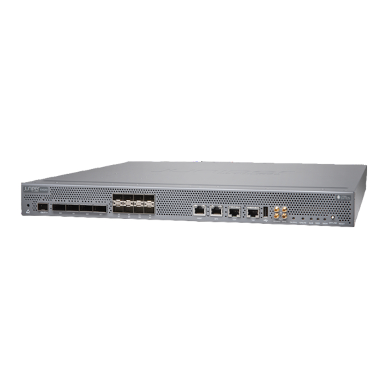
Cooling System | 6 Component Redundancy | 6 Juniper Networks EX9251 Ethernet Switch is an Ethernet-optimized switch that provides carrier-class Ethernet switching. It is a fixed configuration switch with a built-in Routing Engine. It has a throughput of up to 400 gigabits per second (Gbps). - Page 12 Juniper Networks EX Series Ethernet Switches run Junos OS, which provides Layer 2 and Layer 3 switching, routing, and security services. The same Junos OS code base that runs on EX Series switches also runs on all Juniper Networks M Series, MX Series, and T Series routers, and SRX Series Services Gateways.
- Page 13 Management Ethernet port—This port SSD0 LED—indicates the status of the solid- — — connects the switch to a management device state drive labeled SSD0. (or any other device that plugs into an Ethernet connection) for out-of-band management through an Ethernet connection.
- Page 14 — Routing Engine EX9251 switches have a single built-in Routing Engine. It provides switching protocol processes and software processes that control the switch’s interface, the chassis components, system management, and user access to the switch. These switching processes run on top of a kernel that interacts with the Packet Forwarding Engine.
- Page 15 CAUTION: Do not mix AC and DC power supplies in the same chassis. Cooling System The cooling system in an EX9251 switch consists of three fan trays. The fan trays are installed on the rear panel of the chassis. Each fan tray contains one counter rotating fan. See "EX9251 Cooling System"...
-
Page 16: Ex9251 Switch Models
In the event of any failure, the failed component must be replaced immediately. EX9251 Switch Models EX9251 is available in two models—with AC power supply and with DC power supply. Table 1 on page lists the models and the components included in each model. - Page 17 Table 2: CLI Equivalents of Terms Used in Documentation for EX9251 Switches Hardware Description (CLI) Value (CLI) Item in Additional Information Item (CLI) Documentation Chassis EX9251 – Switch chassis "Chassis Physical Specifications of an EX9251 Switch" on page 10 Routing...
-
Page 18: Ex9251 Chassis
Table 2: CLI Equivalents of Terms Used in Documentation for EX9251 Switches (Continued) Hardware Description (CLI) Value (CLI) Item in Additional Information Item (CLI) Documentation n is a value in the range PEM ( One of the AC or DC power "Power Supplies in an... -
Page 19: Chassis Physical Specifications Of An Ex9251 Switch
14.53 in. (36.91 cm) 1.67 in. (4.24 cm) You can mount an EX9251 switch on four posts of a 19-in. rack or an ETSI rack. Field-Replaceable Units in an EX9251 Switch Field-replaceable units (FRUs) are components that you can replace at your site. The FRUs in EX9251 switches are hot-removable and hot-insertable. - Page 20 • Power supplies • Fan trays • Transceivers NOTE: If you have a Juniper J-Care service contract, register any addition, change, or upgrade of hardware components at https:/ /www.juniper.net/customers/support/tools/updateinstallbase/ Failure to do so can result in significant delays if you need replacement parts. This note does not apply if you replace existing components with the same type of component.
-
Page 21: Leds On The Front Panel Of An Ex9251 Switch
LEDs on the Front Panel of an EX9251 Switch The four rate-selectable ports on the front panel of an EX9251 switch has four LEDs each, which indicate the link status and activity on the port. Figure 4 on page 12 shows the LEDs on the rate- selectable ports. - Page 22 (Continued) Table 5: Link/Activity LED on the Rate-Selectable Ports Color/State Port Speed 100G Not applicable Not applicable A 10G module is plugged LED 1 Green in, the port link is up, and there is no alarm or failure. Not applicable Not applicable The port link is down.
- Page 23 Not applicable No 10G module is plugged in. The eight 10-Gigabit Ethernet SFP+ ports on the front panel of an EX9251 switch has one LED each, which indicate the link status and activity on the port. Figure 5 on page 14 shows the LEDs on the SFP + ports labeled 1/0, 1/2, 1/4, and 1/6.
- Page 24 LED on the port labeled 1/2 LED on the port labeled 1/6 — — Figure 6: LEDs on the SFP+ Ports Labeled 1/1, 1/3, 1/5, and 1/7 LED on the port labeled 1/1 LED on the port labeled 1/5 — —...
- Page 25 Figure 7 on page 16 shows the LEDs on the management port and Figure 8 on page 16 shows the LEDs on the BITS port. Table 7 on page 16 describes the functions of the LEDs on the other ports on the front panel.
- Page 26 (Continued) Table 7: Front Panel LEDs Color State Description On steadily The switch has loaded Linux. Blinking The switch is starting Linux. – The switch is offline. OK/FAIL Green On steadily The switch is functioning normally. Blinking The switch has failed. –...
- Page 27 (Continued) Table 7: Front Panel LEDs Color State Description SSD0 Green Blinking SSD0 is being accessed by the switch. – SSD0 is not active or not being accessed. SSD1 Green Blinking SSD1 is being accessed by the switch. – SSD1 is not active or not being accessed. Link/Activity LED on the Green Blinking...
-
Page 28: Ex9251 Cooling System
The cooling system components work together to keep all switch components within the acceptable temperature range. The cooling system in an EX9251 switch consists of three fan trays. Under normal operating conditions, the fans in the fan trays run at a moderate speed. Temperature sensors inside the chassis monitor the temperature of the switch components. - Page 29 Each fan tray contains one counter rotating fan. See Figure 9 on page 20 Figure 10 on page Figure 9: Fan Tray in an EX9251 Switch Figure 10: Faceplate of a Fan Tray in an EX9251 Switch Screw Latch — —...
- Page 30 See Figure 11 on page Figure 11: Airflow Through the EX9251 Switch Chassis Cooling System in the Power Supplies The power supplies are self-cooling units. Each power supply has its own built-in fan that cools the power supply.
- Page 31 Software initialization is complete and the fan is functioning normally. steadily Fan tray is faulty and not functioning normally. steadily – Fan tray is not present. RELATED DOCUMENTATION Clearance Requirements for Airflow and Hardware Maintenance for EX9251 Switches | 46...
-
Page 32: Ex9251 Power System
An EX9251 switch uses either AC or DC power supplies. You can install up to two power supplies in slots labeled 0 and 1 on the right side of the rear panel of the chassis. The power supply in EX9251 switches is a hot-insertable and hot-removable field-replaceable unit (FRU). - Page 33 It has a separate protective earthing terminal (sized for 10-32 screws) on the rear panel of the chassis in addition to the grounding pin of the power supply cord. This separate protective earthing terminal must be permanently connected to earth. Figure 13: AC Power Supply in an EX9251 Switch...
- Page 34 AC Power Supply LEDs and Other Components Figure 14 on page 25 shows the LEDs and other components on an AC power supply without the AC power cord retainer installed. Figure 14: LEDs and Other Components on an AC Power Supply Without the AC Power Cord Retainer Installed Handle Fault LED...
- Page 35 Output status LED Ejector lever — — Table 9 on page 26 describes the LEDs on the AC power supply. Table 9: AC Power Supply LEDs Label Color State Description AC OK Unlit The power supply is disconnected from power source, or the power supply is not receiving power.
- Page 36 It has a separate protective earthing terminal (sized for 10-32 screws) on the rear panel of the chassis. This separate protective earthing terminal must be permanently connected to earth. Figure 16: DC Power Supply in an EX9251 Switch DC Power Supply LEDs and Other Components Figure 17 on page 27 shows the DC power supply status LEDs and other components on a DC power supply.
-
Page 37: Ac Power Cord Specifications For An Ex9251 Switch
AC Power Cord Specifications for an EX9251 Switch Each AC power supply has a single AC appliance inlet located on the faceplate that requires a dedicated AC power feed. A detachable AC power cord is supplied with the AC power supply. The coupler is type C13 as described by International Electrotechnical Commission (IEC) standard 60320. - Page 38 Table 11 on page Table 11: AC Power Cord Specifications Country/Region Electrical Specifications Plug Standards Juniper Model Number Argentina 250 VAC, 10 A, 50 Hz IRAM 2073 Type RA/3 CBL-EX-PWR-C13-AR Australia...
- Page 39 (Continued) Table 11: AC Power Cord Specifications Country/Region Electrical Specifications Plug Standards Juniper Model Number South Africa 250 VAC, 10 A, 50 Hz SABS 164/1:1992 Type CBL-EX-PWR-C13-SA ZA/13 Switzerland 250 VAC, 10 A, 50 Hz SEV 6534-2 Type 12G CBL-EX-PWR-C13-SZ...
-
Page 40: Power Requirements For Ex9251 Switch Components
Power Requirements for EX9251 Switch Components IN THIS SECTION Power Requirements for EX9251 Switch Components | 31 Calculating System Thermal Output | 32 Use the information in this topic to determine the power requirements for your switch. -
Page 41: Power Supply Specifications For Ex9251 Switches
Power consumption in watts * 3.41 = system thermal output in BTU/hr 240 W * 3.41 = 818.4 BTU/hr Power Supply Specifications for EX9251 Switches Table 15 on page 33 lists the AC power system electrical specifications. - Page 42 Table 15: AC Power System Electrical Specifications Item Specifications AC input voltage Operating range: 100 through 240 VAC AC input line frequency 50–60 Hz (nominal) AC system current rating • 3.2 A @ 100 VAC • 1.37 A @ 240 VAC AC system input power 312 W Table 16 on page 33...
- Page 43 Table 17: DC Power System Electrical Specifications Item Specifications DC input voltage Operating range: –44 through –72 VDC DC system input current rating 20 A@ –44 VDC (maximum) DC system input power • 331 W • 7.75 A @ –44 VDC Table 18 on page 34 lists the DC power supply electrical specifications.
-
Page 44: Site Planning, Preparation, And Specifications
C HAPTER Site Planning, Preparation, and Specifications Site Preparation Checklist for an EX9251 Switch | 36 EX9251 Site Guidelines and Requirements | 37 EX9251 Network Cable and Transceiver Planning | 51 EX9251 Management Cable Specifications and Pinouts | 61... -
Page 45: Site Preparation Checklist For An Ex9251 Switch
Site Preparation Checklist for an EX9251 Switch The checklist in Table 19 on page 36 summarizes the tasks you need to perform to prepare a site for installing an EX9251 switch. Table 19: Site Preparation Checklist Item or Task For More Information... -
Page 46: Ex9251 Site Guidelines And Requirements
Plan the cable routing and Management Cable Specifications management. "Specifications of Cables and Wires That Connect to Acquire cables and connectors: Ports on the Front Panel in an EX9251 Switch" on page 62 • Determine the number of cables needed based on your planned configuration. -
Page 47: Environmental Requirements And Specifications For Ex Series Switches
Clearance Requirements for Airflow and Hardware Maintenance for EX9251 Switches | 46 Rack and Cabinet Requirements for EX9251 Switches | 48 Environmental Requirements and Specifications for EX Series Switches The switch must be installed in a rack or cabinet housed in a dry, clean, well-ventilated, and temperature-controlled environment. - Page 48 (Continued) Table 20: EX Series Switch Environmental Tolerances Switch or Environment Tolerance device Altitude Relative Humidity Temperature Seismic No performance Normal operation Normal operation ensured Complies with EX2200 degradation up to ensured in the relative in the temperature range Zone 4 (except 10,000 feet humidity range 10%...
- Page 49 (Continued) Table 20: EX Series Switch Environmental Tolerances Switch or Environment Tolerance device Altitude Relative Humidity Temperature Seismic No performance Normal operation Normal operation ensured Complies with EX3400 degradation up to ensured in the relative in the temperature range Zone 4 10,000 feet humidity range 10% 32°...
- Page 50 (Continued) Table 20: EX Series Switch Environmental Tolerances Switch or Environment Tolerance device Altitude Relative Humidity Temperature Seismic No performance Normal operation Complies with EX4550 • EX4550-32F switches degradation up to ensured in the relative Zone 4 — Normal operation 10,000 feet humidity range 10% earthquake...
- Page 51 (Continued) Table 20: EX Series Switch Environmental Tolerances Switch or Environment Tolerance device Altitude Relative Humidity Temperature Seismic No performance Normal operation Normal operation is Complies with EX4650 degradation to ensured in the relative ensured in the Zone 4 6,000 feet humidity range 10% temperature range 32°...
- Page 52 (Continued) Table 20: EX Series Switch Environmental Tolerances Switch or Environment Tolerance device Altitude Relative Humidity Temperature Seismic No performance Normal operation Normal operation is Complies with EX9204 degradation up to ensured in the relative ensured in the Zone 4 10,000 feet humidity range 5% temperature range 32°...
-
Page 53: General Site Guidelines
Altitude Relative Humidity Temperature Seismic No performance Normal operation Normal operation ensured Complies with EX9251 degradation up to ensured in relative in temperature range of Telcordia The maximum 10,000 ft humidity range of 5% to 32° F (0° C) to 104° F... -
Page 54: Site Electrical Wiring Guidelines
• Follow the prescribed electrostatic discharge (ESD) prevention procedures to prevent damaging the equipment. Static discharge can cause components to fail completely or intermittently over time. • Install the device in a secure area, so that only authorized personnel can access the device. Site Electrical Wiring Guidelines Table 21 on page 45 describes the factors you must consider while planning the electrical wiring at... -
Page 55: Clearance Requirements For Airflow And Hardware Maintenance For Ex9251 Switches
Electrical hazards as a result of power surges conducted over the lines into the equipment. Clearance Requirements for Airflow and Hardware Maintenance for EX9251 Switches When planning the site for installing an EX9251 switch, you must ensure sufficient clearance around the switch. Follow these clearance requirements:... - Page 56 Figure 19 on page 47 for reference. Figure 19: Airflow Through the EX9251 Switch Chassis • If you are mounting the switch on a rack or cabinet along with other equipment, ensure that the exhaust from other equipment does not blow into the intake vents of the chassis.
-
Page 57: Rack And Cabinet Requirements For Ex9251 Switches
Chassis Rack and Cabinet Requirements for EX9251 Switches You can mount an EX9251 switch on four-posts of a 19-in rack or an ETSI rack or in a cabinet that contains a 19-in. rack or an ETSI rack. Rack requirements consist of: •... - Page 58 Table 22: Rack Requirements and Specifications Rack Requirement Guidelines Rack type You can mount the device on a rack that provides bracket holes or hole patterns spaced at 1 U (1.75 in. or 4.45 cm) increments and meets the size and strength requirements to support the weight.
- Page 59 • Cabinet airflow requirements Table 23 on page 50 provides the cabinet requirements and specifications. Table 23: Cabinet Requirements and Specifications Cabinet Requirement Guidelines Cabinet size • You can mount the device in a cabinet that contains a 19-in. rack as defined by the Electronic Components Industry Association (http:/ /www.ecianow.org) or...
-
Page 60: Ex9251 Network Cable And Transceiver Planning
Calculating the Fiber-Optic Cable Power Margin for EX Series Devices | 59 Pluggable Transceivers Supported on EX9251 Switches The network ports on the front panel in EX9251 switches support transceivers. You can find the list of transceivers supported on EX9251 switches and information about those transceivers in the... -
Page 61: Sfp+ Direct Attach Copper Cables For Ex Series Switches
ZR or ZR+) can potentially cause thermal damage to or reduce the lifespan of the host equipment. Any damage to the host equipment due to the use of third-party optical modules or cables is the users’ responsibility. Juniper Networks will accept no liability for any damage caused due to such use. - Page 62 Juniper Networks. If you face a problem running a Juniper device that uses third-party optical modules or cables, JTAC may help you diagnose host-related issues if the observed issue is not, in the opinion of JTAC, related to the use of the third-party optical modules or cables.
- Page 63 • EX8208—Hardware Compatibility Tool page for EX8208 • EX8216—Hardware Compatibility Tool page for EX8216 • EX9251—Hardware Compatibility Tool page for EX9251 • EX9253—Hardware Compatibility Tool page for EX9253 Standards Supported by These Cables The cables comply with the following standards: •...
-
Page 64: Qsfp+ Direct Attach Copper Cables For Ex Series Switches
IN THIS SECTION Cable Specifications | 55 DAC Cables Supported on EX3400, EX4300, EX4550, EX4600, EX9251, and EX9253 Switches | 56 Quad small form-factor pluggable plus (QSFP+) direct attach copper (DAC) cables are suitable for in-rack connections between QSFP+ ports on EX3400, EX4300, EX4550, EX4600, EX9251, and EX9253 switches. -
Page 65: Overview Of Ex Series Switches: Fiber-Optic Cable Signal Loss, Attenuation, And Dispersion
Figure 22: QSFP+ Direct Attach Copper Cables DAC Cables Supported on EX3400, EX4300, EX4550, EX4600, EX9251, and EX9253 Switches For the list of DAC cables supported on EX3400, EX4300, EX4550, EX4600, EX9251, and EX9253 switches and the specifications of these cables, see: •... - Page 66 To determine the power budget and power margin needed for fiber-optic connections, you need to understand how signal loss, attenuation, and dispersion affect transmission. EX Series switches use various types of network cables, including multimode and single-mode fiber-optic cable. Signal Loss in Multimode and Single-Mode Fiber-Optic Cable Multimode fiber is large enough in diameter to allow rays of light to reflect internally (bounce off the walls of the fiber).
-
Page 67: Calculate The Fiber-Optic Cable Power Budget For Ex Series Devices
For single-mode transmission, modal dispersion is not a factor. However, at higher bit rates and over longer distances, chromatic dispersion limits the maximum link length. An efficient optical data link must have enough light to exceed the minimum power that the receiver requires to operate within its specifications. -
Page 68: Calculating The Fiber-Optic Cable Power Margin For Ex Series Devices
Calculating the Fiber-Optic Cable Power Margin for EX Series Devices Calculating the Fiber-Optic Cable Before calculating the power margin, calculate the power budget (see Power Budget for EX Series Devices Calculate the link's power margin when planning fiber-optic cable layout and distances to ensure that fiber-optic connections have sufficient signal power to overcome system loss and still satisfy the minimum input requirements of the receiver for the required performance level. - Page 69 (Continued) Table 24: Estimated Values for Factors Causing Link Loss Link-Loss Factor Estimated Link-Loss Value Sample (LL) Calculation Values Splice 0.5 dBm This example assumes 2 splices. Loss for two splices: (2) * (0.5 dBm) = 1 dBm Fiber attenuation This example assumes the link is 2 •...
-
Page 70: Ex9251 Management Cable Specifications And Pinouts
IN THIS SECTION Management Cable Specifications | 61 Specifications of Cables and Wires That Connect to Ports on the Front Panel in an EX9251 Switch | 62 Grounding Cable and Lug Specifications for EX9251 Switches | 62 USB Port Specifications for an EX Series Switch | 64... -
Page 71: Specifications Of Cables And Wires That Connect To Ports On The Front Panel In An Ex9251 Switch
100Base-T operation Grounding Cable and Lug Specifications for EX9251 Switches IN THIS SECTION Grounding Points Specifications for an EX9251 Switch | 63 Grounding Cable Specifications for an EX9251 Switch | 63 Grounding Lug Specifications for an EX9251 Switch | 64... - Page 72 To ensure proper operation and to meet safety and electromagnetic interference (EMI) requirements, you must connect an EX9251 switch to earth ground before you connect power to the switch. You must use the protective earthing terminal on the rear panel of the switch chassis to connect the switch to earth ground.
-
Page 73: Usb Port Specifications For An Ex Series Switch
USB flash drive for information about how your USB flash drive is formatted. Console Port Connector Pinout Information for an EX9251 Switch The console port on an EX9251 switch are RS-232 serial interfaces. This port connects the switch to a console management port. - Page 74 NOTE: If your laptop or PC does not have a DB-9 plug connector pin and you want to connect your laptop or PC directly to an EX9251 switch, use a combination of the RJ-45 to DB-9 socket adapter supplied with the switch and a USB to DB-9 plug adapter. You must provide the USB to DB-9 plug adapter.
-
Page 75: Rj-45 To Db-9 Serial Port Adapter Pinout Information
RJ-45 to DB-9 Serial Port Adapter Pinout Information The console port on a Juniper Networks device is an RS-232 serial interface that uses an RJ-45 connector to connect to a management device such as a laptop or a desktop PC. If your laptop or... - Page 76 Table 30: RJ-45 Management Port Connector Pinout Information Signal Description TRP1+ Transmit/receive data pair 1 TRP1- Transmit/receive data pair 1 TRP2+ Transmit/receive data pair 2 TRP3+ Transmit/receive data pair 3 TRP3- Transmit/receive data pair 3 TRP2- Transmit/receive data pair 2 TRP4+ Transmit/receive data pair 4 TRP4-...
-
Page 77: Initial Installation And Configuration
C HAPTER Initial Installation and Configuration Unpacking and Mounting the EX9251 Switch | 69 Connecting the EX9251 to Power | 82 Connecting the EX9251 to External Devices | 99 Connecting the EX9251 to the Network | 105 Configuring Junos OS on the EX9251 | 109... -
Page 78: Unpacking And Mounting The Ex9251 Switch
Mounting an EX9251 Switch on a Rack or Cabinet | 73 Unpacking an EX9251 Switch EX9251 switches are shipped in a cardboard carton, secured with foam packing material. The carton has an accessory compartment and contains the quick start instructions. -
Page 79: Parts Inventory (Packing List) For An Ex9251 Switch
Switch Models" on page 7 for more information. If any part on the packing list is missing, contact your customer service representative or contact Juniper customer care from within the U.S. or Canada by telephone at 1-888-314-5822. For international-dial or direct-dial options in countries without toll-free numbers, see https:/ /www.juniper.net/support/... - Page 80 Ring lugs to connect to DC power source cables AC power cord appropriate for your geographical location Label, “Small Parts Enclosed” Label, “Accessories Contents” USB flash drive with Junos OS Read me first document Affidavit for T1 connection Juniper Networks Product Warranty End User License Agreement Document sleeve...
-
Page 81: Register Products-Mandatory To Validate Slas
Installing and Connecting an EX9251 Switch The EX9251 switch chassis is a rigid sheet-metal structure that houses all components of the switch. The switch is shipped in a cardboard carton, secured with foam packing material. The carton has an... -
Page 82: Mounting An Ex9251 Switch On A Rack Or Cabinet
Installing an EX9251 Switch in an ETSI Rack | 77 You can mount an EX9251 switch on four posts of a rack that complies with either of the following standards or in a cabinet with a rack that complies with either of the following standards by using the... -
Page 83: Mounting An Ex9251 Switch On A 19-In. Rack
The weight of a fully configured chassis is 22.7 lb (10.3 kg). We recommend that you install cover panels in the unused power supply slots. Mounting an EX9251 Switch on a 19-in. Rack Before you begin mounting the switch on a 19-in. rack, ensure that you have the following parts and tools available: •... - Page 84 • Two rear-mounting brackets (provided in the accessory box shipped with the switch) • Eight screws to secure the chassis to the rack (not provided) • Cover panels for power supply slots To mount the switch on a 19-in. rack: Place the switch on a flat, stable surface.
- Page 85 (see Figure Figure 24: Mounting an EX9251 Switch on a Rack by Using Front-Mounting Brackets Ensure that the switch chassis is level by verifying that all screws on one side of the rack are aligned with the screws on the other side.
-
Page 86: Installing An Ex9251 Switch In An Etsi Rack
Figure 5 shows the switch fully secured and installed on four posts of a rack. Figure 27: EX9251 Mounted on Four Posts of a 19-in. Rack Installing an EX9251 Switch in an ETSI Rack Before you begin mounting the switch on an ETSI rack, ensure that you have the following parts and tools available: •... - Page 87 • Two rear-mounting brackets (provided in the accessory box shipped with the switch) • Four ETSI brackets. Figure 28 on page 78 shows the ETSI brackets provided with EX9251 switches. Figure 28: ETSI Brackets • Eight screws to secure the chassis to the rack (not provided) •...
- Page 88 Have a second person secure the switch to the rack by using the appropriate screws. Tighten the screws (see Figure 31 on page 79). Figure 31: Mounting an EX9251 Switch on an ETSI Rack by Using Front-Mounting Brackets...
- Page 89 ETSI brackets attached to the front-mounting brackets. Figure 32: An EX9251 Switch Mounted on an ETSI Rack by Using Front-Mounting Brackets 10. Attach two ETSI brackets to the rear-mounting brackets by using the M5 Pan Head screws with...
- Page 90 Figure 35 on page 81 shows the switch fully secured and installed on four posts of a rack. Figure 35: EX9251 Mounted on Four Posts of an ETSI Rack RELATED DOCUMENTATION Rack-Mounting and Cabinet-Mounting Warnings | 174...
-
Page 91: Connecting The Ex9251 To Power
IN THIS SECTION Connect Earth Ground to an EX Series Switch | 82 Connecting AC Power to an EX9251 Switch and Powering on the Switch | 92 Connecting DC Power to an EX9251 Switch and Powering on the Switch | 95... - Page 92 Parts and Tools Required for Connecting an EX Series Switch to Earth Ground Before you begin connecting an EX Series switch to earth ground, ensure you have the parts and tools required for your switch. Table 33 on page 83 lists the earthing terminal location, grounding cable and lug specifications, and parts needed for connecting an EX Series switch to earth ground.
- Page 93 (Continued) Table 33: Parts Required for Connecting an EX Series Switch to Earth Ground Switch Earthing Grounding Grounding Lug Screws and Additional Terminal Cable Specifications Washers Information Location Requirements EX2300 Rear panel of • • • EX2300 EX2300 EX2300 the chassis switches switches except switches...
- Page 94 (Continued) Table 33: Parts Required for Connecting an EX Series Switch to Earth Ground Switch Earthing Grounding Grounding Lug Screws and Additional Terminal Cable Specifications Washers Information Location Requirements EX3200 Rear panel of 14 AWG Panduit For EX3200 • the chassis (2 mm²), LCC10-14BWL or Switches, see...
- Page 95 (Continued) Table 33: Parts Required for Connecting an EX Series Switch to Earth Ground Switch Earthing Grounding Grounding Lug Screws and Additional Terminal Cable Specifications Washers Information Location Requirements EX4300 Rear panel of 14-10 AWG Panduit • Two 10-32 switches the chassis STR (2.5-6 LCD10-10A-L or...
- Page 96 (Continued) Table 33: Parts Required for Connecting an EX Series Switch to Earth Ground Switch Earthing Grounding Grounding Lug Screws and Additional Terminal Cable Specifications Washers Information Location Requirements EX6210 Rear panel of The grounding Panduit LCD2-14A- • Two ¼ -20 the chassis cable must be Q or equivalent...
- Page 97 (Continued) Table 33: Parts Required for Connecting an EX Series Switch to Earth Ground Switch Earthing Grounding Grounding Lug Screws and Additional Terminal Cable Specifications Washers Information Location Requirements EX8216 Two earthing 2 AWG Panduit LCD2-14A- • Two ¼ -20 x terminals: (33.6 mm²), Q or equivalent...
- Page 98 Switch Earthing Grounding Grounding Lug Screws and Additional Terminal Cable Specifications Washers Information Location Requirements EX9251 Rear panel of 12 AWG Panduit Two 10-32 Grounding the chassis (2.5 mm²), LCD10-10A-L or screws— Cable and Lug minimum 90° C equivalent— provided...
- Page 99 Table 34: Special Instructions to Follow Before Connecting Earth Ground to an EX Series Switch Switch Special Instructions EX3200 and Some early variants of EX3200 and EX4200 switches for which the Juniper Networks EX4200 model number on the label next to the protective earthing terminal is from 750-021 xxx require 10-24x.25 in. screws.
- Page 100 Connecting Earth Ground to an EX Series Switch To connect earth ground to an EX Series switch: 1. Verify that a licensed electrician has attached the cable lug to the grounding cable. 2. Connect one end of the grounding cable to a proper earth ground, such as the rack in which the switch is mounted.
-
Page 101: Connecting Ac Power To An Ex9251 Switch And Powering On The Switch
• An external management device You can install up to two AC power supplies in an EX9251 switch. The AC power supply in an EX9251 switch is a hot-removable and hot-insertable field-replaceable unit (FRU). You can remove and replace it while the switch is running without turning off power to the switch or disrupting switching functions. - Page 102 Ensure that the power supply is fully inserted and latched securely in the chassis. See "Installing an AC Power Supply in an EX9251 Switch" on page 125. If the AC power source outlet has a power switch, set it to the off position.
- Page 103 Handle Fault LED — — Input status LED AC power cord retainer — — Output status LED Ejector lever — — Press the small tab on the retainer strip to loosen the loop. Slide the loop until you have enough space to insert the power cord coupler into the inlet.
-
Page 104: Connecting Dc Power To An Ex9251 Switch And Powering On The Switch
128. Ensure that you have the following parts and tools available to connect DC power to an EX9251 switch: • An ESD wrist strap • DC power source cables (minimum 12 AWG (2.5 mm²), minimum 60°C wire or as permitted by local code) •... - Page 105 • Phillips (+) screwdriver, number 2 • A multimeter You can install up to two DC power supplies in an EX9251 switch. The DC power supply in an EX9251 switch is a hot-removable and hot-insertable field-replaceable unit (FRU). You can remove and replace it while the switch is running without turning off power to the switch or disrupting switching functions.
- Page 106 CAUTION: Ensure that power connections maintain the proper polarity. The power source cables might be labeled (+) and (–) to indicate their polarity. There is no standard color coding for DC power cables. The color coding used by the external DC power source at your site determines the color coding for the leads on the power cables that attach to the terminal studs on each power supply.
- Page 107 CAUTION: Ensure that each power cable lug seats flush against the surface of the terminal block as you tighten the screws. Ensure that each screw is properly threaded into the terminal block. Before tightening each screw that you insert into the terminal block, ensure that you are able to spin the screw freely with your fingers.
-
Page 108: Connecting The Ex9251 To External Devices
Connecting the EX9251 to External Devices IN THIS SECTION Connect a Device to a Network for Out-of-Band Management | 100 Connect a Device to a Management Console Using an RJ-45 Connector | 100 Connecting the EX9251 Switch to External Clocking and Timing Devices | 102... -
Page 109: Connect A Device To A Network For Out-Of-Band Management
Connect a Device to a Network for Out-of-Band Management Ensure that you have an Ethernet cable that has an RJ-45 connector at either end. Figure 43 on page shows the RJ-45 connector of the Ethernet cable supplied with the device. Figure 43: RJ-45 Connector on an Ethernet Cable You can monitor and manage these devices by using a dedicated management channel. - Page 110 Figure 45 on page 101 shows the RJ-45 connector on the Ethernet cable. Figure 45: RJ-45 Connector on an Ethernet Cable NOTE: If your laptop or desktop PC does not have a DB-9 plug connector pin and you want to connect your laptop or desktop PC directly to the device, use a combination of the RJ-45-to- DB-9 socket adapter supplied with the device and a USB-to-DB-9 plug adapter.
-
Page 111: Connecting The Ex9251 Switch To External Clocking And Timing Devices
Figure 46: Connect a Device to a Management Console Through a Console Server Figure 47: Connect a Device Directly to a Management Console Connecting the EX9251 Switch to External Clocking and Timing Devices IN THIS SECTION Connecting 1-PPS and 10-MHz Timing Devices to the Switch | 103... -
Page 112: Connecting 1-Pps And 10-Mhz Timing Devices To The Switch
EX9251 switches support external clock synchronization for Synchronous Ethernet and external inputs. The connections to the switch are made through the front panel. Figure 48 on page 103 shows the ports that are used to connect the switch to external clocking and timing devices. -
Page 113: Connecting A Time-Of-Day Device To The Switch
Table 35: Clocking Port on an EX9251 Switch Callout Label Description 4 and 5 10MHz GPS input and output ports. (See Figure 48 on page 103) 1PPS Connecting a Time-of-Day Device to the Switch A time-of-day port labeled ToD, on the front panel of the switch enables you to connect external timing devices. -
Page 114: Connecting The Ex9251 To The Network
Ensure that you have a rubber safety cap available to cover the transceiver. The transceivers for Juniper Networks devices are hot-removable and hot-insertable field-replaceable units (FRUs). You can remove and replace them without powering off the device or disrupting the device... - Page 115 Juniper Networks. If you face a problem running a Juniper device that uses third-party optical modules or cables, JTAC may help you diagnose host-related issues if the observed issue is not, in the opinion of JTAC, related to the use of the third-party optical modules or cables.
- Page 116 LASER WARNING: Do not leave a fiber-optic transceiver uncovered except when inserting or removing a cable. The rubber safety cap keeps the port clean and protects your eyes from accidental exposure to laser light. 4. If the port in which you want to install the transceiver is covered with a dust cover, remove the dust cover and save it in case you need to cover the port later.
-
Page 117: Connect A Fiber-Optic Cable
CAUTION: Do not let fiber-optic cable hang free from the connector. Do not allow fastened loops of cable to dangle, which stresses the cable at the fastening point. CAUTION: Avoid bending fiber-optic cable beyond its minimum bend radius. An arc smaller than a few inches in diameter can damage the cable and cause problems that are difficult to diagnose. -
Page 118: Configuring Junos Os On The Ex9251
Connecting and Configuring an EX9251 Switch (CLI Procedure) | 110 EX9251 Switch Default Configuration Each EX9251 switch is programmed with a factory default configuration that contains the values set for each configuration parameter when a switch is shipped. The default configuration file sets values for... -
Page 119: Connecting And Configuring An Ex9251 Switch (Cli Procedure)
• IP address of a DNS server • Password for the root user The EX9251 switch is shipped with the Junos OS preinstalled and ready to be configured when the switch is powered on. There are two 16-MB internal NAND Flash memory devices located on the... - Page 120 baseboard for BIOS storage. You can insert the USB storage device into the USB slot on the front panel. The switch also has two built-in M.2-based solid-state drives (SSDs) (labeled SSD0 and SSD1). There are three copies of the software: one each on the SSD drives and one on a USB flash drive that can be inserted into the slot in the faceplate of the RE module.
- Page 121 [edit] encrypted-password root@# set system root-authentication encrypted-password [edit] public-key root@# set system root-authentication ssh-dsa [edit] public-key root@# set system root-authentication ssh-rsa Configure the name of the switch. If the name includes spaces, enclose the name in double quotation marks (“ ”). [edit] host-name root@# set system host-name...
- Page 122 10. Configure the IP address and prefix length for the switch’s Ethernet interface. [edit] address/prefix-length root@# set interfaces fxp0 unit 0 family inet address 11. Configure the IP address of a backup router, which is used only while the routing protocol is not running.
- Page 123 name-server { address ; interfaces { fxp0 { unit 0 { family inet { address/prefix-length ; address 16. Commit the configuration to activate it on the switch. [edit] root@# commit 17. (Optional) Configure additional properties by adding the necessary configuration statements. Then commit the changes to activate them on the switch.
-
Page 124: Maintaining Components
C HAPTER Maintaining Components Routine Maintenance Procedures for EX9251 Switches | 116 Maintaining the EX9251 Cooling System | 118 Maintaining the EX9251 Power System | 122 Maintaining Transceivers | 132 Maintain Fiber-Optic Cables | 141... -
Page 125: Routine Maintenance Procedures For Ex9251 Switches
• Check the status-reporting devices on the front panel in EX9251 switches—alarms and LEDs. • Inspect the air filter or fan tray at the rear of the switch, replacing it every 6 months for optimum cooling system performance. -
Page 126: Maintaining The Routing Engine In Ex9251 Switches
Maintaining the Routing Engine in EX9251 Switches For optimum switch performance, verify the condition of the Routing Engine on a regular basis. On a regular basis: • Check the LEDs on the front panel to view information about the status of the Routing Engine. -
Page 127: Maintaining The Ex9251 Cooling System
• Phillips (+) screwdriver, number 2 • A replacement fan tray The fan tray in an EX9251 switch is a hot-insertable and hot-removable field-replaceable unit (FRU). You can remove and replace it while the switch is running without turning off power to the switch or disrupting switching functions. -
Page 128: Installing A Fan Tray In An Ex9251 Switch
4. Grasp the fan tray handle, and pull it out approximately 1 to 3 inches. 5. Place one hand under the fan tray to support it, and pull the fan tray completely out of the chassis. Figure 51: Removing a Fan Tray from an EX9251 Switch Installing a Fan Tray in an EX9251 Switch... - Page 129 However, you must replace the fan tray within two minutes of removing the fan tray to prevent the chassis from overheating. The fan tray in an EX9251 switch is a hot-insertable and hot-removable field-replaceable unit (FRU). You can remove and replace it while the switch is running without turning off power to the switch or disrupting switching functions.
-
Page 130: Maintaining Fan Trays In Ex9251 Switches
A major alarm is triggered when a fan fails and a minor alarm and a major alarm are triggered when a fan tray is removed. • To display the status of the cooling system, issue the show chassis environment command. The output for EX9251 switches is similar to the following: user@switch> show chassis environment Class Item... -
Page 131: Maintaining The Ex9251 Power System
IN THIS SECTION Powering Off an EX9251 Switch | 122 Removing an AC Power Supply from an EX9251 Switch | 123 Installing an AC Power Supply in an EX9251 Switch | 125 Removing a DC Power Supply from an EX9251 Switch | 126... -
Page 132: Removing An Ac Power Supply From An Ex9251 Switch
• Ensure that you have taken the necessary precautions to prevent electrostatic discharge (ESD) Prevention of Electrostatic Discharge Damage damage. See • Ensure that you have the following parts and tools available to power off an EX9251 switch: • An ESD wrist strap • An external management device such as a PC •... - Page 133 • A replacement power supply or a cover panel for the power supply slot The AC power supply in an EX9251 switch is a hot-removable and hot-insertable field-replaceable unit (FRU). You can remove and replace it while the switch is running without turning off power to the switch or disrupting switching functions.
-
Page 134: Installing An Ac Power Supply In An Ex9251 Switch
(FRU). You can remove and replace it while the switch is running without turning off power to the switch or disrupting switching functions. You can install up to two AC power supplies in an EX9251 switch. The power supplies install in the slots on the rear panel of the chassis. -
Page 135: Removing A Dc Power Supply From An Ex9251 Switch
Figure 54: Installing an AC Power Supply in an EX9251 Switch NOTE: If you have a Juniper J-Care service contract, register any addition, change, or upgrade of hardware components at https:/ /www.juniper.net/customers/support/tools/updateinstallbase/... - Page 136 • A replacement power supply or cover panel for the power supply slot The DC power supply in an EX9251 switch is a hot-removable and hot-insertable field-replaceable unit (FRU). You can remove and replace it while the switch is running without turning off power to the switch or disrupting switching functions.
-
Page 137: Installing A Dc Power Supply In An Ex9251 Switch
11. Pull the power supply straight out of the chassis. 12. Either replace a power supply promptly or install a cover panel over the empty slot. Figure 56: Removing a DC Power Supply from an EX9251 Switch Installing a DC Power Supply in an EX9251 Switch... - Page 138 (FRU). You can remove and replace it while the switch is running without turning off power to the switch or disrupting switching functions. You can install up to two DC power supplies in an EX9251 switch. All DC power supplies install in the slots on the rear panel of the chassis.
-
Page 139: Maintaining Power Supplies In Ex9251 Switches
Figure 57: Installing a DC Power Supply in an EX9251 Switch NOTE: If you have a Juniper J-Care service contract, register any addition, change, or upgrade of hardware components at https:/ /www.juniper.net/customers/support/tools/updateinstallbase/... - Page 140 • Make sure that the power and grounding cables are arranged so that they do not obstruct access to other switch components. • Routinely check the status LEDs on the power supply faceplates and the front panel in EX9251 switches to determine whether the power supplies are functioning normally.
-
Page 141: Maintaining Transceivers
• Rubber safety caps to cover the transceiver and fiber-optic cable connector • A dust cover to cover the port or a replacement transceiver The transceivers for Juniper Networks devices are hot-removable and hot-insertable field-replaceable units (FRUs). You can remove and replace them without powering off the device or disrupting device functions. - Page 142 To remove a transceiver from a device: 1. Place the antistatic bag or antistatic mat on a flat, stable surface. 2. Wrap and fasten one end of the ESD wrist strap around your bare wrist, and connect the other end of the strap to the ESD point on the switch.
- Page 143 CAUTION: Before removing the transceiver, make sure that you open the ejector lever completely until you hear it click. This prevents damage to the transceiver. b. Grasp the transceiver ejector lever and gently slide the transceiver approximately 0.5 in. (1.3 cm) straight out of the port.
-
Page 144: Install A Transceiver
Juniper Networks. If you face a problem running a Juniper device that uses third-party optical modules or cables, JTAC may help you diagnose host-related issues if the observed issue is not, in the opinion of JTAC, related to the use of the third-party optical modules or cables. - Page 145 CAUTION: To prevent electrostatic discharge (ESD) damage to the transceiver, do not touch the connector pins at the end of the transceiver. 1. Wrap and fasten one end of the ESD wrist strap around your bare wrist, and connect the other end of the strap to the ESD point on the switch.
-
Page 146: Remove A Qsfp28 Transceiver
CAUTION: Do not leave a fiber-optic transceiver uncovered except when inserting or removing cable. The safety cap keeps the port clean and protects your eyes from accidental exposure to laser light. 8. If there is a cable management system, arrange the cable in the cable management system to prevent the cable from dislodging or developing stress points. - Page 147 • A dust cover to cover the port or a replacement transceiver The transceivers for Juniper Networks devices are hot-removable and hot-insertable field-replaceable units (FRUs). You can remove and replace them without powering off the device or disrupting the device functions.
-
Page 148: Install A Qsfp28 Transceiver
Ensure that you have a rubber safety cap available to cover the transceiver. The transceivers for Juniper Networks devices are hot-removable and hot-insertable field-replaceable units (FRUs). You can remove and replace them without powering off the device or disrupting the device functions. - Page 149 Juniper Networks. If you face a problem running a Juniper device that uses third-party optical modules or cables, JTAC may help you diagnose host-related issues if the observed issue is not, in the opinion of JTAC, related to the use of the third-party optical modules or cables.
-
Page 150: Maintain Fiber-Optic Cables
LASER WARNING: Do not look directly into a fiber-optic transceiver or into the ends of fiber-optic cables. Fiber-optic transceivers and fiber-optic cable connected to a transceiver emit laser light that can damage your eyes. CAUTION: Do not leave a fiber-optic transceiver uncovered except when inserting or removing cable. -
Page 151: Connect A Fiber-Optic Cable
Connect a Fiber-Optic Cable Before you connect a fiber-optic cable to an optical transceiver installed in a device, ensure that you Laser and LED Safety Guidelines have taken the necessary precautions for safe handling of lasers (see and Warnings To connect a fiber-optic cable to an optical transceiver installed in a device: LASER WARNING: Do not look directly into a fiber-optic transceiver or into the ends of fiber-optic cables. -
Page 152: Disconnect A Fiber-Optic Cable
• A rubber safety cap to cover the transceiver • A rubber safety cap to cover the fiber-optic cable connector Juniper Networks devices have optical transceivers to which you can connect fiber-optic cables. To disconnect a fiber-optic cable from an optical transceiver installed in the device: 1. - Page 153 • When you unplug a fiber-optic cable from a transceiver, place rubber safety caps over the transceiver and on the end of the cable. • Anchor fiber-optic cables to prevent stress on the connectors. When attaching a fiber-optic cable to a transceiver, be sure to secure the fiber-optic cable so that it does not support its own weight as it hangs to the floor.
-
Page 154: Troubleshooting Hardware
C HAPTER Troubleshooting Hardware Troubleshooting EX9251 Components | 146... -
Page 155: Troubleshooting Ex9251 Components
Troubleshooting EX9251 Components IN THIS SECTION Troubleshooting the Cooling System in an EX9251 Switch | 146 Troubleshooting Power Supplies in an EX9251 Switch | 147 Troubleshoot Temperature Alarms in EX Series Switches | 149 Troubleshooting the Cooling System in an EX9251 Switch... -
Page 156: Troubleshooting Power Supplies In An Ex9251 Switch
(critical alarm and • The temperature of the switch exceeds the automatic shutdown of the power supplies). SEE ALSO Maintaining Fan Trays in EX9251 Switches | 121 Troubleshooting Power Supplies in an EX9251 Switch IN THIS SECTION Problem | 148... - Page 157 Online in the rows labeled State must indicate that each of the power supplies is functioning normally. The output for EX9251 switches is similar to the following: user@switch> show chassis environment pem PEM 0 status:...
-
Page 158: Troubleshoot Temperature Alarms In Ex Series Switches
If a power supply is not functioning normally, perform the following steps to diagnose and correct the problem: • If a major alarm condition occurs, issue the show chassis alarms command to determine the source of the problem. • If all power supplies have failed, the system temperature might have exceeded the threshold, causing the system to shut down. - Page 159 Problem Description EX Series switches trigger a temperature alarm FPC 0 EX-PFE1 Temp Too Hot when the switch temperature becomes too hot. Cause Temperature sensors in the chassis monitor the temperature of the chassis. The switch triggers an alarm if a fan fails or if the temperature of the chassis exceeds permissible levels for some other reason. Solution When the switch triggers a temperature alarm such as the FPC 0 EX-PFE1 Temp Too Hot alarm, use the show...
- Page 160 CB 0 Intake 36 degrees C / 96 degrees F CB 0 Exhaust A 34 degrees C / 93 degrees F CB 0 Exhaust B 40 degrees C / 104 degrees F CB 0 ACBC 39 degrees C / 102 degrees F CB 0 XF A 46 degrees C / 114 degrees F CB 0 XF B...
- Page 161 Top Front Fan Spinning at intermediate-speed Bottom Front Fan Spinning at intermediate-speed lists the output fields for the show chassis environment command. The table lists Table 38 on page 152 output fields in the approximate order in which they appear. Table 38: show chassis environment Output Fields Field Name Field Description...
- Page 162 2. Issue the command . This command displays the chassis show chassis temperature-thresholds temperature threshold settings. Following is a sample output on an EX9208 switch. The output is similar on other EX Series switches. show chassis temperature-thresholds (EX9208 Switch) user@ host> show chassis temperature-thresholds Fan speed Yellow alarm Red alarm...
- Page 163 (Continued) Table 39: show chassis temperature-thresholds Output Fields Field Name Field Description Yellow or amber alarm Temperature threshold, in degrees Celsius, that triggers a yellow or amber alarm. • Normal—The temperature threshold that must be exceeded on the device to trigger a yellow or amber alarm when the fans are running at full speed.
- Page 164 2. Replace the faulty fan module or fan tray. 3. If the above two checks show no problems, open a support case using the Case Manager link at https:/ /www.juniper.net/support/ or call 1-888-314-5822 (toll-free within the United States and Canada) or 1-408-745-9500 (from outside the United States).
-
Page 165: Contacting Customer Support And Returning The Chassis Or Components
C HAPTER Contacting Customer Support and Returning the Chassis or Components Returning an EX9251 Chassis or Components | 157... -
Page 166: Returning An Ex9251 Chassis Or Components
Packing an EX9251 Switch or Component | 161 Returning an EX9251 Switch or Component for Repair or Replacement If you need to return a switch or hardware component to Juniper Networks for repair or replacement, follow this procedure: 1. Determine the serial number of the chassis if you need to return the switch. If you need to return one or more components, determine the serial number for each component. -
Page 167: Locating The Serial Number On An Ex9251 Switch Or Component
Locating the Serial Number ID Label on an EX9251 Switch Chassis The serial number ID label is located on the top of the chassis on an EX9251 switch (ee Figure Figure 63: Location of the Serial Number ID Label on EX9251 Switch Chassis... -
Page 168: Locating Serial Number Id Labels On Fru Components
Locating Serial Number ID Labels on FRU Components The power supplies and fan trays installed in EX9251 switches are field-replaceable units (FRUs). You can remove and replace them without powering off the switch. For each of these FRUs, you must remove the FRU from the switch chassis to see the FRU’s serial number ID label. -
Page 169: Contact Customer Support To Obtain A Return Material Authorization
Removing a Fan Tray from an EX9251 Switch | 118 Contact Customer Support to Obtain a Return Material Authorization If you need to return a device or hardware component to Juniper Networks for repair or replacement, obtain a Return Material Authorization (RMA) number from Juniper Networks Technical Assistance Center (JTAC). -
Page 170: Packing An Ex9251 Switch Or Component
Packing an EX9251 Switch | 162 Packing EX9251 Switch Components for Shipping | 163 If you are returning an EX9251 switch or component to Juniper Networks for repair or replacement, pack the item as described in this topic. Before you begin packing the switch or component, ensure you have: Contact Customer Support to Obtain Return Material Authorization •... -
Page 171: Packing An Ex9251 Switch
• An ESD wrist strap Packing an EX9251 Switch If you need to transport the switch to another location or return the switch to Juniper Networks, you need to pack the switch securely in its original packaging to prevent damage during transportation. -
Page 172: Packing Ex9251 Switch Components For Shipping
• Antistatic bag, one for each component • An ESD wrist strap To pack EX9251 switch components, follow the instructions here. CAUTION: Do not stack switch components. Return individual components in separate boxes if they do not fit together on one level in the shipping box. -
Page 173: Safety And Compliance Information
C HAPTER Safety and Compliance Information General Safety Guidelines and Warnings | 166 Definitions of Safety Warning Levels | 167 Qualified Personnel Warning | 169 Warning Statement for Norway and Sweden | 169 Fire Safety Requirements | 170 Installation Instructions Warning | 171 Chassis and Component Lifting Guidelines | 172 Restricted Access Warning | 172 Ramp Warning | 174... - Page 174 Multiple Power Supplies Disconnection Warning | 200 TN Power Warning | 201 Agency Approvals for EX9251 Switches | 202 Compliance Statements for EMC Requirements for EX Series Switches | 204 Compliance Statements for Acoustic Noise for EX Series Switches | 208...
-
Page 175: General Safety Guidelines And Warnings
General Safety Guidelines and Warnings The following guidelines help ensure your safety and protect the device from damage. The list of guidelines might not address all potentially hazardous situations in your working environment, so be alert and exercise good judgment at all times. •... -
Page 176: Definitions Of Safety Warning Levels
• Some parts of the chassis, including AC and DC power supply surfaces, power supply unit handles, SFB card handles, and fan tray handles might become hot. The following label provides the warning for hot surfaces on the chassis: • Always ensure that all modules, power supplies, and cover panels are fully inserted and that the installation screws are fully tightened. - Page 177 Waarschuwing Dit waarschuwingssymbool betekent gevaar. U verkeert in een situatie die lichamelijk letsel kan veroorzaken. Voordat u aan enige apparatuur gaat werken, dient u zich bewust te zijn van de bij elektrische schakelingen betrokken risico's en dient u op de hoogte te zijn van standaard maatregelen om ongelukken te voorkomen. Varoitus Tämä...
-
Page 178: Qualified Personnel Warning
Qualified Personnel Warning WARNING: Only trained and qualified personnel should install or replace the device. Waarschuwing Installatie en reparaties mogen uitsluitend door getraind en bevoegd personeel uitgevoerd worden. Varoitus Ainoastaan koulutettu ja pätevä henkilökunta saa asentaa tai vaihtaa tämän laitteen. Avertissement Tout installation ou remplacement de l'appareil doit être réalisé... -
Page 179: Fire Safety Requirements
In addition, you should establish procedures to protect your equipment in the event of a fire emergency. Juniper Networks products should be installed in an environment suitable for electronic equipment. We recommend that fire suppression equipment be available in the event of a fire in the vicinity of the equipment and that all local fire, safety, and electrical codes and ordinances be observed when you install and operate your equipment. -
Page 180: Installation Instructions Warning
NOTE: To keep warranties effective, do not use a dry chemical fire extinguisher to control a fire at or near a Juniper Networks device. If a dry chemical fire extinguisher is used, the unit is no longer eligible for coverage under a service agreement. -
Page 181: Chassis And Component Lifting Guidelines
Chassis and Component Lifting Guidelines • Before moving the device to a site, ensure that the site meets the power, environmental, and clearance requirements. • Before lifting or moving the device, disconnect all external cables and wires. • As when lifting any heavy object, ensure that your legs bear most of the weight rather than your back. - Page 182 Avertissement Cet appareil est à installer dans des zones d'accès réservé. Ces dernières sont des zones auxquelles seul le personnel de service peut accéder en utilisant un outil spécial, un mécanisme de verrouillage et une clé, ou tout autre moyen de sécurité. L'accès aux zones de sécurité...
-
Page 183: Ramp Warning
Ramp Warning WARNING: When installing the device, do not use a ramp inclined at more than 10 degrees. Waarschuwing Gebruik een oprijplaat niet onder een hoek van meer dan 10 graden. Varoitus Älä käytä sellaista kaltevaa pintaa, jonka kaltevuus ylittää 10 astetta. Avertissement Ne pas utiliser une rampe dont l'inclinaison est supérieure à... - Page 184 Les directives ci-dessous sont destinées à assurer la protection du personnel: • Le rack sur lequel est monté le Juniper Networks switch doit être fixé à la structure du bâtiment.
- Page 185 Le seguenti direttive vengono fornite per garantire la sicurezza personale: • Il Juniper Networks switch deve essere installato in un telaio, il quale deve essere fissato alla struttura dell'edificio. • Questa unità deve venire montata sul fondo del supporto, se si tratta dell'unica unità...
- Page 186 Para garantizar su seguridad, proceda según las siguientes instrucciones: • El Juniper Networks switch debe instalarse en un bastidor fijado a la estructura del edificio. • Colocar el equipo en la parte inferior del bastidor, cuando sea la única unidad en el...
-
Page 187: Grounded Equipment Warning
Följande riktlinjer ges för att trygga din säkerhet: • Juniper Networks switch måste installeras i en ställning som är förankrad i byggnadens struktur. • Om denna enhet är den enda enheten på ställningen skall den installeras längst ned på... -
Page 188: Radiation From Open Port Apertures Warning
Avvertenza Questo dispositivo deve sempre disporre di una connessione a massa. Seguire le istruzioni indicate in questa guida per connettere correttamente il dispositivo a massa. Advarsel Denne enheten på jordes skikkelig hele tiden. Følg instruksjonene i denne veiledningen for å jorde enheten. Aviso Este equipamento deverá... -
Page 189: Laser And Led Safety Guidelines And Warnings
Class 1 LED Product Warning | 182 Laser Beam Warning | 182 Juniper Networks devices are equipped with laser transmitters, which are considered a Class 1 Laser Product by the U.S. Food and Drug Administration and are evaluated as a Class 1 Laser Product per IEC/EN 60825-1 requirements. - Page 190 General Laser Safety Guidelines When working around ports that support optical transceivers, observe the following safety guidelines to prevent eye injury: • Do not look into unterminated ports or at fibers that connect to unknown sources. • Do not examine unterminated optical ports with optical instruments. •...
- Page 191 Class 1 LED Product Warning LASER WARNING: Class 1 LED product. Waarschuwing Klasse 1 LED-product. Varoitus Luokan 1 valodiodituote. Avertissement Alarme de produit LED Class I. Warnung Class 1 LED-Produktwarnung. Avvertenza Avvertenza prodotto LED di Classe 1. Advarsel LED-produkt i klasse 1. Aviso Produto de classe 1 com LED.
-
Page 192: Maintenance And Operational Safety Guidelines And Warnings
Aviso Não olhe fixamente para o raio, nem olhe para ele directamente com instrumentos ópticos. ¡Atención! No mirar fijamente el haz ni observarlo directamente con instrumentos ópticos. Varning! Rikta inte blicken in mot strålen och titta inte direkt på den genom optiska instrument. - Page 193 aanbevolen is. Gebruikte batterijen dienen overeenkomstig fabrieksvoorschriften weggeworpen te worden. Varoitus Räjähdyksen vaara, jos akku on vaihdettu väärään akkuun. Käytä vaihtamiseen ainoastaan saman- tai vastaavantyyppistä akkua, joka on valmistajan suosittelema. Hävitä käytetyt akut valmistajan ohjeiden mukaan. Avertissement Danger d'explosion si la pile n'est pas remplacée correctement. Ne la remplacer que par une pile de type semblable ou équivalent, recommandée par le fabricant.
- Page 194 Waarschuwing Alvorens aan apparatuur te werken die met elektrische leidingen is verbonden, sieraden (inclusief ringen, kettingen en horloges) verwijderen. Metalen voorwerpen worden warm wanneer ze met stroom en aarde zijn verbonden, en kunnen ernstige brandwonden veroorzaken of het metalen voorwerp aan de aansluitklemmen lassen.
- Page 195 Varning! Tag av alla smycken (inklusive ringar, halsband och armbandsur) innan du arbetar på utrustning som är kopplad till kraftledningar. Metallobjekt hettas upp när de kopplas ihop med ström och jord och kan förorsaka allvarliga brännskador; metallobjekt kan också sammansvetsas med kontakterna. Lightning Activity Warning WARNING: Do not work on the system or connect or disconnect cables during periods of lightning activity.
- Page 196 6 in. (15.2 cm) of clearance around the ventilation openings. Waarschuwing Om te voorkomen dat welke switch van de Juniper Networks router dan ook oververhit raakt, dient u deze niet te bedienen op een plaats waar de maximale aanbevolen omgevingstemperatuur van 40°...
- Page 197 ¡Atención! Para impedir que un encaminador de la serie Juniper Networks switch se recaliente, no lo haga funcionar en un área en la que se supere la temperatura ambiente máxima recomendada de 40° C. Para impedir la restricción de la entrada de aire, deje un espacio mínimo de 15,2 cm alrededor de las aperturas para ventilación.
-
Page 198: General Electrical Safety Guidelines And Warnings
General Electrical Safety Guidelines and Warnings WARNING: Certain ports on the device are designed for use as intrabuilding (within- GR-1089-CORE ) the-building) interfaces only (Type 2 or Type 4 ports as described in and require isolation from the exposed outside plant (OSP) cabling. To comply with NEBS (Network Equipment-Building System) requirements and protect against lightning must not be surges and commercial power disturbances, the intrabuilding ports... -
Page 199: Action To Take After An Electrical Accident
• Canada—Canadian Electrical Code, Part 1, CSA C22.1. • Suitable for installation in Information Technology Rooms in accordance with Article 645 of the National Electrical Code and NFPA 75. Peut être installé dans des salles de matériel de traitement de l’information conformément à l’article 645 du National Electrical Code et à... -
Page 200: Prevention Of Electrostatic Discharge Damage
Prevention of Electrostatic Discharge Damage Device components that are shipped in antistatic bags are sensitive to damage from static electricity. Some components can be impaired by voltages as low as 30 V. You can easily generate potentially damaging static voltages whenever you handle plastic or foam packing material or if you move components across plastic or carpets. -
Page 201: Ac Power Electrical Safety Guidelines
• When removing or installing a component that is subject to ESD damage, always place it component- side up on an antistatic surface, in an antistatic card rack, or in an antistatic bag (see Figure 67 on page 192). If you are returning a component, place it in an antistatic bag before packing it. Figure 67: Placing a Component into an Antistatic Bag CAUTION: ANSI/TIA/EIA-568 cables such as Category 5e and Category 6 can get electrostatically charged. -
Page 202: Ac Power Disconnection Warning
“ATTENTION: CET APPAREIL COMPORTE PLUS D'UN CORDON D'ALIMENTATION. AFIN DE PRÉVENIR LES CHOCS ÉLECTRIQUES, DÉBRANCHER TOUT CORDON D'ALIMENTATION AVANT DE FAIRE LE DÉPANNAGE.” • AC-powered devices are shipped with a three-wire electrical cord with a grounding-type plug that fits only a grounding-type power outlet. Do not circumvent this safety feature. Equipment grounding must comply with local and national electrical codes. -
Page 203: Dc Power Electrical Safety Guidelines
Avertissement Avant de travailler sur un châssis ou à proximité d'une alimentation électrique, débrancher le cordon d'alimentation des unités en courant alternatif. Warnung Bevor Sie an einem Chassis oder in der Nähe von Netzgeräten arbeiten, ziehen Sie bei Wechselstromeinheiten das Netzkabel ab bzw. Avvertenza Prima di lavorare su un telaio o intorno ad alimentatori, scollegare il cavo di alimentazione sulle unità... -
Page 204: Dc Power Disconnection Warning
NOTE: Primary overcurrent protection is provided by the building circuit breaker. This breaker must protect against excess currents, short circuits, and earth grounding faults in accordance with NEC ANSI/NFPA 70. • Ensure that the polarity of the DC input wiring is correct. Under certain conditions, connections with reversed polarity might trip the primary circuit breaker or damage the equipment. - Page 205 disjoncteur en position fermée (OFF) et, à l'aide d'un ruban adhésif, bloquer la poignée du disjoncteur en position OFF. Warnung Vor Ausführung der folgenden Vorgänge ist sicherzustellen, daß die Gleichstromschaltung keinen Strom erhält. Um sicherzustellen, daß sämtlicher Strom abgestellt ist, machen Sie auf der Schalttafel den Unterbrecher für die Gleichstromschaltung ausfindig, stellen Sie den Unterbrecher auf AUS, und kleben Sie den Schaltergriff des Unterbrechers mit Klebeband in der AUS-Stellung fest.
-
Page 206: Dc Power Grounding Requirements And Warning
DC Power Grounding Requirements and Warning An insulated grounding conductor that is identical in size to the grounded and ungrounded branch circuit supply conductors but is identifiable by green and yellow stripes is installed as part of the branch circuit that supplies the device. The grounding conductor is a separately derived system at the supply transformer or motor generator set. - Page 207 48 V. When disconnecting power, the proper wiring sequence is –48 V to –48 V, +RTN to +RTN, then ground to ground. Note that the ground wire must always be connected first and disconnected last. Waarschuwing De juiste bedradingsvolgorde verbonden is aarde naar aarde, +RTN naar +RTN, en –48 V naar –...
-
Page 208: Dc Power Wiring Terminations Warning
¡Atención! Wire a fonte de alimentação de DC Usando os talões apropriados nan EXtremidade da fiação. Ao conectar a potência, a seqüência apropriada da fiação é moída para moer, +RTN a +RTN, então –48 V a –48 V. Ao desconectar a potência, a seqüência apropriada da fiação é... -
Page 209: Multiple Power Supplies Disconnection Warning
Avvertenza Quando occorre usare trecce, usare connettori omologati, come quelli a occhiello o a forcella con linguette rivolte verso l'alto. I connettori devono avere la misura adatta per il cablaggio e devono serrare sia l'isolante che il conduttore. Advarsel Hvis det er nødvendig med flertrådede ledninger, brukes godkjente ledningsavslutninger, som for eksempel lukket sløyfe eller spadetype med oppoverbøyde kabelsko. -
Page 210: Tn Power Warning
Avertissement Cette unité est équipée de plusieurs raccordements d'alimentation. Pour supprimer tout courant électrique de l'unité, tous les cordons d'alimentation doivent être débranchés. Warnung Diese Einheit verfügt über mehr als einen Stromanschluß; um Strom gänzlich von der Einheit fernzuhalten, müssen alle Stromzufuhren abgetrennt sein. Avvertenza Questa unità... -
Page 211: Agency Approvals For Ex9251 Switches
Agency Approvals for EX9251 Switches IN THIS SECTION Compliance Statement for Argentina | 203 EX9251 switches comply with the following standards: • Safety • CAN/CSA-C22.2 No. 60950-1 Safety of Information Technology Equipment • UL 60950-1 Information Technology Equipment - Safety - Part 1: General Requirements •... - Page 212 • EN 55024:2010 (CISPR 24:2010) Information technology equipment - Immunity characteristics - Limits and methods of measurement • IEC/EN 61000 Immunity Test • AS/NZS CISPR 32:2015 Australia/New Zealand Radiated and Conducted Emissions • FCC 47 CFR Part 15 USA Radiated and Conducted Emissions •...
-
Page 213: Compliance Statements For Emc Requirements For Ex Series Switches
Compliance Statements for Acoustic Noise for EX Series Switches Compliance Statements for EMC Requirements for EX Series Switches IN THIS SECTION Canada | 204 Taiwan | 205 European Community | 205 Israel | 206 Japan | 206 Korea | 206 United States | 207 FCC Part 15 Statement | 207 This topic applies to hardware devices in the EX Series product family, which includes EX Series... - Page 214 acceptable method of connection. In some cases, the inside wiring associated with a single line individual service can be extended by means of a certified connector assembly. The customer should be aware that compliance with the above conditions might not prevent degradation of service in some situations.
- Page 215 Israel The preceding translates as follows: Warning: This product is Class A. In residential environments, the product may cause radio interference, and in such a situation, the user may be required to take adequate measures. Japan The preceding translates as follows: This is a Class A device.
- Page 216 The preceding translates as follows: This equipment is Industrial (Class A) electromagnetic wave suitability equipment and seller or user should take notice of it, and this equipment is to be used in the places except for home United States The device has been tested and found to comply with the limits for a Class A digital device, pursuant to Part 15 of the FCC Rules.
-
Page 217: Compliance Statements For Acoustic Noise For Ex Series Switches
Compliance Statements for Acoustic Noise for EX Series Switches This topic applies to hardware devices in the EX Series product family, which includes EX Series switches, the EX Series Redundant Power System (RPS), and the XRE200 External Routing Engine. Maschinenlärminformations-Verordnung - 3. GPSGV, der höchste Schalldruckpegel beträgt 70 dB(A) oder weniger gemäss EN ISO 7779 Translation: The emitted sound pressure is below 70 dB(A) per EN ISO 7779.
Need help?
Do you have a question about the EX9251 and is the answer not in the manual?
Questions and answers