Table of Contents
Advertisement
Quick Links
Advertisement
Chapters
Table of Contents
Troubleshooting

Related Manuals for Juniper EX9208


Summary of Contents for Juniper EX9208
- Page 1 EX9208 Switch Hardware Guide Published 2022-01-16...
- Page 2 The Juniper Networks product that is the subject of this technical documentation consists of (or is intended for use with) Juniper Networks software. Use of such software is subject to the terms and conditions of the End User License Agreement ("EULA") posted at https:/ /support.juniper.net/support/eula/.
-
Page 3: Table Of Contents
AC Power Supply in an EX9208 Switch | 43 AC Power Supply Specifications for EX9208 Switches | 45 AC Power Cord Specifications for an EX9208 Switch | 46 AC Power Supply LEDs in an EX9208 Switch | 49 DC Power Supply in an EX9208 Switch | 50... - Page 4 Configuring Rate Selectability on an EX9200-12QS Line Card to Enable Different Port Speeds | 110 Configuring Rate Selectability at the PIC Level | 110 Configuring Rate Selectability at the Port Level | 112 Site Planning, Preparation, and Specifications Site Preparation Checklist for an EX9208 Switch | 116...
- Page 5 Environmental Requirements and Specifications for EX Series Switches | 118 General Site Guidelines | 125 Site Electrical Wiring Guidelines | 125 Clearance Requirements for Airflow and Hardware Maintenance for an EX9208 Switch | 126 Rack Requirements | 128 Cabinet Requirements | 130...
- Page 6 Moving the Mounting Brackets for Center-Mounting an EX9200 Switch | 156 Mounting an EX9200 Switch on a Rack or Cabinet Using a Mechanical Lift | 158 Mounting an EX9208 Switch on a Rack or Cabinet Without Using a Mechanical Lift | 162 Connecting the EX9208 to Power | 165...
- Page 7 Maintaining the Air Filter in EX9200 Switches | 208 Maintaining the EX9208 Power System | 209 Removing an AC Power Supply from an EX9208 Switch | 210 Installing an AC Power Supply in an EX9208 Switch | 211 Removing a DC Power Supply from an EX9208 Switch | 214...
- Page 8 How to Handle Fiber-Optic Cables | 274 Maintaining the EX9208 Cable Management Brackets | 275 Installing Cable Management Brackets on an EX9208 Switch | 275 Removing Cable Management Brackets from an EX9208 Switch | 277 Removing an EX9208 from a Rack or Cabinet | 277...
- Page 9 Removing an EX9200 Switch from a Rack or Cabinet Using a Mechanical Lift | 278 Removing an EX9208 Switch from a Rack or Cabinet Without Using a Mechanical Lift | 279 Troubleshooting Hardware Troubleshooting EX9200 Components | 283 Troubleshooting the Cooling System in an EX9200 Switch | 283...
- Page 10 Fire Safety Requirements | 333 Installation Instructions Warning | 334 Chassis and Component Lifting Guidelines | 335 Restricted Access Warning | 335 Ramp Warning | 337 Rack-Mounting and Cabinet-Mounting Warnings | 337 Grounded Equipment Warning | 341 Radiation from Open Port Apertures Warning | 342 Laser and LED Safety Guidelines and Warnings | 343 Maintenance and Operational Safety Guidelines and Warnings | 346 General Electrical Safety Guidelines and Warnings | 352...
- Page 11 Compliance Statements for Acoustic Noise for EX Series Switches | 372...
-
Page 12: About This Guide
Use this guide to install hardware and perform initial software configuration, routine maintenance, and troubleshooting for the EX9208 switch. After completing the installation and basic configuration procedures covered in this guide, refer to the Junos OS documentation for information about further software configuration. -
Page 13: Overview
C HAPTER Overview EX9208 System Overview | 2 EX9208 Chassis | 25 EX9208 Cooling System | 39 EX9208 Power System | 42 EX9200 Host Subsystem | 57 EX9200 Line Cards | 78... -
Page 14: Ex9208 System Overview
The EX9208 switch has a throughput of up to 4.8 terabits per second (Tbps) or up to 240 gigabits per second (Gbps) per slot full duplex. The EX9208 switch is a modular system that... -
Page 15: Benefits
You can manage EX9208 switches by using the same interfaces that you use for managing other devices running the Juniper Networks Junos operating system (Junos OS)—the CLI, the Network and Security Manager (NSM), and Junos Space. Benefits Simplified network architecture—EX9208 switches deliver a simple, secure, virtualized network environment that increases business agility. -
Page 16: Chassis Physical Specifications
Chassis Physical Specifications The EX9208 switch is eight rack units (8 U) in size. Five EX9208 switches can fit in a standard 48 U rack. Each EX9208 switch is designed to optimize rack space and cabling. See Figure 1 on page... -
Page 17: Host Subsystem
Configurations" on page Line Cards The EX9208 switch has six horizontal line card slots and supports line rate for each line card. The line cards in EX9208 switches combine a Packet Forwarding Engine and Ethernet interfaces in a single assembly. Line cards are field-replaceable units (FRUs) that you can install in the line card slots—labeled 0 through 5—on the front of the switch chassis. - Page 18 Table 1: Line Cards Available for EX9208 Switches Model Description Additional Information EX9200-2C-8XS Line Card EX9200-2C-8XS A line card with two 100-Gigabit Ethernet ports and eight 10- Gigabit Ethernet ports EX9200-4QS Line Card EX9200-4QS A line card with four 40-Gigabit...
-
Page 19: Cooling System
(SFP+) transceivers Cooling System The cooling system in an EX9208 switch is a field-replaceable unit (FRU). It consists of a hot-removable and hot-insertable fan tray. The fan tray contains six fans. The fan tray installs vertically on the right back of the chassis and provides side-to-side chassis cooling. -
Page 20: Ex9208 Switch Configurations
–40 VDC through –70 VDC 2400 W to 2600 W A base-configuration EX9208 switch ships with three low-line (100–120 VAC) or two high-line (200– 240 VAC) AC power supplies. An AC-powered, redundant-configuration EX9208 switch ships with four low-line (100–120 VAC) or four high-line (200–240 VAC) AC power supplies. See "AC Power Supply in... - Page 21 Table 3: EX9208 Switch Hardware Configurations Switch Configuration Configuration Components First Junos OS Release EX9208-BASE3C-AC 20.3R1 • Chassis with craft interface and midplane (base configurationwith 2520 W AC • One EX9200-SF3 module power supplies) • One EX9200-RE2 module • One fan tray •...
- Page 22 (Continued) Table 3: EX9208 Switch Hardware Configurations Switch Configuration Configuration Components First Junos OS Release EX9208-BASE3B-AC 17.1R1 • Chassis with craft interface and midplane (base configuration with 2520 W • One EX9200-SF2 module AC power supplies) • One EX9200-RE2 module •...
- Page 23 (Continued) Table 3: EX9208 Switch Hardware Configurations Switch Configuration Configuration Components First Junos OS Release EX9208-BASE3A-AC 14.1 • Chassis with craft interface and midplane (base configuration with 2520 W • One EX9200-SF2 module AC power supplies) • One EX9200-RE module •...
- Page 24 (Continued) Table 3: EX9208 Switch Hardware Configurations Switch Configuration Configuration Components First Junos OS Release EX9208-REDUND3A-DC 14.1 • Chassis with craft interface and midplane (redundant configuration with • Two EX9200-SF2 modules 2400 W DC power supplies) • Two EX9200-RE modules •...
- Page 25 (Continued) Table 3: EX9208 Switch Hardware Configurations Switch Configuration Configuration Components First Junos OS Release EX9208-REDUND-AC 12.3R2 • Chassis with craft interface and midplane (redundant configuration with • Two EX9200-SF modules 2520 W AC power supplies) • Two EX9200-RE modules •...
-
Page 26: Ex9208 Switch Hardware And Cli Terminology Mapping
NOTE: Power cords and additional power supplies (AC or DC) must be purchased separately. EX9208 Switch Hardware and CLI Terminology Mapping This topic describes the hardware terms used in EX9208 switch documentation and the corresponding terms used in the Junos OS CLI. See... - Page 27 (Continued) Table 4: CLI Equivalents of Terms Used in Documentation for EX9208 Switches Hardware Description (CLI) Value (CLI) Item in Additional Item (CLI) Documentation Information n is a value in the range Routing Engine Routing One of the following: RE module...
- Page 28 (Continued) Table 4: CLI Equivalents of Terms Used in Documentation for EX9208 Switches Hardware Description (CLI) Value (CLI) Item in Additional Item (CLI) Documentation Information n is a value in the range FPC ( Abbreviated name of Line card (The •...
- Page 29 (Continued) Table 4: CLI Equivalents of Terms Used in Documentation for EX9208 Switches Hardware Description (CLI) Value (CLI) Item in Additional Item (CLI) Documentation Information n is a value in the range MIC ( Abbreviated name of Line card •...
- Page 30 (Continued) Table 4: CLI Equivalents of Terms Used in Documentation for EX9208 Switches Hardware Description (CLI) Value (CLI) Item in Additional Item (CLI) Documentation Information n is a value in the range PIC ( Abbreviated name of Line card (The •...
-
Page 31: Chassis Physical Specifications Of An Ex9208 Switch
System" on page Chassis Physical Specifications of an EX9208 Switch The EX9208 switch chassis is a rigid sheet-metal structure that houses the other switch components. Table 5 on page 19 summarizes the physical specifications of the EX9208 switch chassis. See... - Page 32 (Continued) Table 5: Physical Specifications of the EX9208 Switch Chassis Description Weight Height Width Depth Switch Fabric 9.6 lb (4.4 kg) (with 1.25 in. (3.2 cm) 17 in. (43.2 cm) 22 in. (55.9 cm) module (SF Routing Engine module) installed) EX9200-SF3 13.6 lb (6.2 kg)
- Page 33 (Continued) Table 5: Physical Specifications of the EX9208 Switch Chassis Description Weight Height Width Depth EX9200-10XS- 1.54 lb (0.7 kg) 1.25 in. (3.2 cm) 6.67 in. (16.9 cm) 7.86 in. (20 cm) EX9200-20F- 1.2 lb (0.54 kg) 1.25 in. (3.2 cm) 6.67 in.
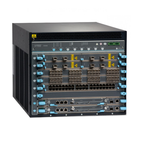
- Page 34 Figure 4: EX9208 Switch Figure 5: EX9208 Switch with AC Power Supplies...
-
Page 35: Field-Replaceable Units In An Ex9200 Switch
Figure 6: EX9208 Switch with DC Power Supplies You can mount an EX9208 switch on a standard 19-in. four-post rack or a standard 800-mm enclosed cabinet. You can mount up to six EX9208 switches in a standard (48 rack unit (U)) rack. - Page 36 You must disable the switch before removing any RE Taking the Host Subsystem Offline in an module. See EX9200 Switch EX9204 Switch Configurations "EX9208 Switch EX9214 Switch Configurations Configurations" on page 8, and Switch Fabric module (SF module) Redundant configuration: •...
-
Page 37: Ex9208 Chassis
NOTE: Line cards are not part of the base or redundant configuration. You must order them separately. NOTE: If you have a Juniper J-Care service contract, register any addition, change, or upgrade of hardware components at https:/ /www.juniper.net/customers/support/tools/updateinstallbase/ Failure to do so can result in significant delays if you need replacement parts. -
Page 38: Understanding Ex9208 Switch Component And Functionality Redundancy
Redundancy The Juniper Networks EX9208 Ethernet Switches are available as fully redundant system. A redundant EX9208 switch configuration is designed so that no single point of failure can cause the entire switch to fail. See "EX9208 Switch Configurations" on page The following hardware components provide redundancy to an EX9208 switch: •... -
Page 39: Craft Interface In An Ex9200 Switch
"DC Power Supply in an EX9208 Switch" on page • Cooling system—The cooling system in EX9208 switches consists of fan tray and air filter. The fan tray contains six fans. Under normal operating conditions, the fans in the fan tray run at less than full speed. - Page 40 NOTE: You can install a line card or an SF module in the multifunctional slot labeled 1|0 in EX9204 switches. The corresponding LED displays information depending on the hardware installed in that slot. Figure 8: Craft Interface in an EX9208 Switch Host subsystem LEDs Alarm cutoff/lamp test button —...
-
Page 41: Host Subsystem Leds
Major alarm LED — Figure 9: Craft Interface in an EX9214 Switch Power supply LEDs Alarm cutoff/lamp test button — — Fan LEDs Alarm relay contacts — — Host subsystem LEDs Line card LEDs and control buttons — — Minor alarm LED Switch Fabric/line card LED and control —... -
Page 42: Fan Leds
Table 7: Host Subsystem LEDs on the Craft Interface Label Status Description MASTER Green Host subsystem is functioning as the primary. Unlit Host subsystem is either functioning as the backup or not installed. ONLINE Green Host subsystem is online and is functioning normally. Unlit Host subsystem is either offline or not installed. -
Page 43: Power Supply (Pem) Leds
Power Supply (PEM) LEDs Each power supply has two LEDs on the craft interface that indicate its status. The LEDs—labeled 0 through 3—are located on the craft interface next to the PEM label. Table 9 on page 31 describes the functions of the power supply LEDs on the craft interface. -
Page 44: Line Card Leds And Control Buttons
(Continued) Table 10: Switch Fabric Module LEDs on the Craft Interface FAIL The SF module has failed. Unlit The SF module is not installed or is not functioning normally. Line Card LEDs and Control Buttons Each line card has two LEDs—OK and FAIL—on the craft interface that indicates its status. The line card LEDs are associated with control buttons and are located along the bottom of the craft interface. -
Page 45: Alarm Relay Contacts
The alarm cutoff/lamp test (ACO/LT) button, located next to the alarm LEDs, is a control button for alarms. You can press the ACO/LT button to deactivate major and minor alarms. Deactivating an alarm turns off both LEDs and deactivates the device attached to the corresponding alarm relay contact on the craft interface. -
Page 46: Midplane In An Ex9200 Switch
Figure 10 on page 34 shows the alarm relay contacts in EX9200 switches. Figure 10: Alarm Relay Contacts in EX9200 Switches Midplane in an EX9200 Switch The midplane is located on the rear of the chassis and forms the rear of the card cage. The Switch Fabric modules (SF modules) and line cards are installed into the midplane from the front of the chassis, and the power supplies install into the midplane from the rear of the chassis. - Page 47 Figure 11 on page 35 shows the midplane in an EX9204 switch. Figure 12 on page 36 shows the midplane in an EX9208 switch. Figure 13 on page 37 shows the midplane in an EX9214 switch. Figure 11: Midplane in an EX9204 Switch...
- Page 48 Figure 12: Midplane in an EX9208 Switch...
-
Page 49: Cable Management Brackets In An Ex9208 Switch
Figure 13: Midplane in an EX9214 Switch Cable Management Brackets in an EX9208 Switch The cable management brackets (see Figure 14 on page 38) consist of plastic dividers located on the left and right sides of each line card slot and Switch Fabric module (SF module) slot. The cable... - Page 50 management brackets allow you to route the cables outside the switch and away from the line cards and SF modules. Figure 14: Cable Management Brackets...
-
Page 51: Ex9208 Cooling System
Airflow Direction in the EX9208 Switch Chassis | 41 The cooling system in an EX9208 switch consists of a fan tray and an air filter. The cooling system components work together to keep all switch components within the acceptable temperature range. - Page 52 Fan tray is a hot-insertable and hot-removable field-replaceable unit (FRU) and contains six fans. The fan tray and air filter install vertically in the rear of the switch. See Figure 16 on page 40 Figure 17 on page Figure 16: Fan Tray for an EX9208 Switch...
- Page 53 Figure 17: Air Filter for an EX9208 Switch Airflow Direction in the EX9208 Switch Chassis The air intake to cool the chassis is located on the side of the chassis next to the air filter. Air is pulled through the chassis toward the fan tray, where it is exhausted out through the side of the chassis. The...
-
Page 54: Ex9208 Power System
You cannot replace a single fan. If one or more fans fail, you must replace the entire fan tray. RELATED DOCUMENTATION Clearance Requirements for Airflow and Hardware Maintenance for an EX9208 Switch | 126 EX9208 Power System IN THIS SECTION... -
Page 55: Ac Power Supply In An Ex9208 Switch
AC Power Supply Description | 43 AC Power Supply Configurations | 45 An EX9208 switch is configurable with two, three, or four AC power supplies. The power supplies connect to the midplane, which distributes the different output voltages produced by the power supplies to the switch components, depending on their voltage requirements. - Page 56 You can install up to four AC power supplies in an EX9208 switch. Power supplies are installed in the rear of the chassis in slots PEM0 through PEM3 (left to right). WARNING: The switch is installed in a restricted-access location. It has a separate protective earthing terminal (sized for UNC 1/4-20 ground lugs) provided on the chassis in addition to the grounding pin of the power supply cord.
-
Page 57: Ac Power Supply Specifications For Ex9208 Switches
The EX9208 switch supports either the low-line (100–120 V) AC power configuration or the high-line (200–240 V) AC power configuration. • In the low-line (100–120 V) AC power configuration, the EX9208 switch contains three or four AC power supplies, located horizontally at the rear of the chassis in slots PEM0 through PEM3 (left to right). -
Page 58: Ac Power Cord Specifications For An Ex9208 Switch
Table 13: AC Power Supply Specifications for an EX9208 Switch Item Specifications AC input voltage Operating range: • Low-voltage line: 100–120 VAC • High-voltage line: 200–240 VAC AC input line frequency 50–60 Hz AC input current rating • Low-voltage line: 16 A •... - Page 59 Table 15 on page 47 provides specifications and Figure 20 on page 48 depicts the plug on the AC power cord provided for each country or region. Table 15: AC Power Cord Specifications for an EX9208 Switch Country Model Number Electrical Specification Plug Type...
- Page 60 (Continued) Table 15: AC Power Cord Specifications for an EX9208 Switch Country Model Number Electrical Specification Plug Type United Kingdom CBL-M-PWR-RA-UK 240 VAC, 50 Hz AC BS89/13 Figure 20: AC Plug Types WARNING: The AC power cord for the switch is intended for use with the switch only and not for any other use.
-
Page 61: Ac Power Supply Leds In An Ex9208 Switch
LED on the craft interface. Table 16 on page 49 describes the LEDs on an AC power supply in an EX9208 switch. Table 16: AC Power Supply LEDs on EX9208 Switches... -
Page 62: Dc Power Supply In An Ex9208 Switch
DC Power Supply Description | 51 DC Power Supply Configurations | 52 An EX9208 switch is configurable with two or four DC power supplies. The power supplies connect to the midplane, which distributes the different output voltages produced by the power supplies to the switch components, depending on their voltage requirements. - Page 63 The DC power supplies in EX9000 switches are hot-insertable and hot-removable field-replaceable units (FRUs). You can install either two or four DC power supplies in an EX9208 switch. Power supplies are installed in the rear of the chassis in slots PEM0 through PEM3 (left to right).
- Page 64 DC Power Supply Configurations In the DC power configuration, the EX9208 switch contains either two or four DC power supplies located at the rear of the chassis in slots PEM0 through PEM3 (left to right). You can upgrade your DC power system from two to four power supplies.
-
Page 65: Dc Power Supply Specifications For Ex9208 Switches
PEM3 Fan tray and line card slots 2 through 5 SEE ALSO Installing a DC Power Supply in an EX9208 Switch | 216 DC Power Supply Specifications for EX9208 Switches Table 18 on page 53 lists the DC power supply specifications for EX9208 switches. -
Page 66: Dc Power Supply Leds In An Ex9208 Switch
NOTE: A host subsystem must be present for the POWER OK LED to be on. Table 20 on page 54 describes the LEDs on a DC power supply in EX9208 switches. Table 20: DC Power Supply LEDs in EX9208 Switches... -
Page 67: Power Requirements For Ex9200 Switch Components
(Continued) Table 20: DC Power Supply LEDs in EX9208 Switches Color Description BRKR ON Green DC power input is present and the DC power supply circuit breaker is turned on. DC power supply circuit breaker is turned off. INPUT OK... - Page 68 Reserved Power (watt) Redundant system • • EX9204 switch: 690 W EX9204 switch: 690 W • • EX9208 switch: 800 W EX9208 switch: 800 W • • EX9214 switch: 1530 W EX9214 switch: 1910 W EX9200-SF Switch Fabric module 150 W...
-
Page 69: Ex9200 Host Subsystem
Table 21: EX9200 Switch Component Power Requirements (Continued) Component Typical Power (watt) Reserved Power (watt) EX9200-32XS line card 550 W 610 W EX9200-40T line card 206 W 239 W EX9200-40F line card 219 W 239 W EX9200-40F-M line card 219 W 239 W EX9200-40XS line card 465 W... -
Page 70: Routing Engine Module In An Ex9200 Switch
You can install either one or two host subsystems in the front panel of an EX9204 or an EX9208 switch. A base configuration EX9204 and EX9208 switch has one host subsystem. A redundant configuration EX9204 and EX9208 switch has a second host subsystem. - Page 71 8, and . You can add a second RE module to the configuration for redundancy. NOTE: We recommend that you install two RE modules in EX9204, EX9208, and EX9214 switches for redundancy. The RE module performs the following functions: • Provides switching functionality to the switch through the switching plane •...
- Page 72 CAUTION: The EX9200-RE module and the EX9200-RE2 module are not interoperable. Do not install both the RE modules in the same switch chassis. NOTE: Starting with Junos OS Release 16.1, you can use EX9200 switches as an aggregation device in Junos Fusion Enterprise. Starting with Junos OS Release 17.4, you can use EX9200 switches with EX9200-RE2 module installed in it as an aggregation device in Junos Fusion Enterprise.
- Page 73 • USB port—Hosts a removable media interface through which you can install the Junos OS manually. USB Port Specifications for an EX Series Switch • SATA SSD 1 and SATA SSD 2 slots—Host primary storage for software images, configuration files, and microcode.
-
Page 74: Routing Engine Module Leds In An Ex9200 Switch
• Status LEDs—Indicate the status of the EX9200-RE2 module. Each EX9200-RE2 module has five LEDs labeled MASTER, ONLINE, OK/FAIL, DISK1, and DISK2 on the faceplate. • ONLINE/OFFLINE button—Turns the EX9200-RE2 module online or offline when pressed. • USB1 and USB2 ports—Host a removable media interface using which you can install the Junos OS USB Port Specifications for an EX Series Switch manually. - Page 75 Table 23: LEDs on the EX9200-RE Routing Engine Module LED Label Status State and Description MASTER Blue RE module is functioning as the primary. Unlit RE module is either functioning as the backup or not installed. STORAGE Green Blinking—Indicates activity on the SSD. ONLINE Green •...
- Page 76 (Continued) Table 24: LEDs on the EX9200-RE2 Routing Engine Module LED Label Status State and Description Green When the RE module is powering on: • Blinking slowly (LED is lit for a period of time and is unlit for thrice that period of time that follows, and this pattern is repeated)—RE module is coming online.
-
Page 77: Switch Fabric Module In An Ex9200 Switch
Switch Fabric modules (SF modules) are installed horizontally on the front panel of the switch chassis. You can install either one or two SF modules in an EX9204 or EX9208 switch and two or three SF modules in an EX9214 switch. A base-configuration EX9204 or EX9208 switch has only one SF module, EX9204 Switch Configurations and a base-configuration EX9214 switch has two SF modules. - Page 78 Figure 24 on page 66 shows the original SF module, EX9200-SF. Figure 24: SF Module EX9200-SF Starting with Junos OS Release 14.1, a high-speed SF module, EX9200-SF2, is available. Compared to the original SF module, EX9200-SF, the EX9200-SF2 offers increased bandwidth, providing higher- capacity traffic support in settings that require greater interface density (slot and capacity scale).
- Page 79 NOTE: When you upgrade from an EX9200-SF module to an EX9200-SF2 module in an EX9200 switch, the SF module types can coexist in the switch during the upgrade. However, you must replace that EX9200-SF module with another EX9200-SF2 module for normal switch operation. Upgrading an EX9200-SF to an EX9200-SF2 Figure 25 on page 67 shows the high-speed SF module, EX9200-SF2.
- Page 80 The SF modules install horizontally into the front of the chassis. If any slots are empty, you must install a cover panel. The SF module has the following components: • Chassis management Ethernet switch • I2C bus logic, used for low-level communication with each component •...
-
Page 81: Switch Fabric Module Leds In An Ex9200 Switch
Switch Fabric Module LEDs in an EX9200 Switch The Switch Fabric module (SF module) has three LEDs on the module faceplate. Table 25 on page 69 describes the functions of these LEDs. For information about the LEDs on the EX9200-SF3, see Table 25 on page Table 25: SF Module LEDs of an EX9200 Switch... - Page 82 EX9200-SF3 Fabric Bandwidth Performance and Redundancy | 74 EX9200-SF3 Maximum Power Consumption per Ambient Temperature and CB Slot | 75 Interoperability with Existing Hardware | 76 EX9200-SF3 Unsupported Functions and Capabilities from Legacy Switch Fabric Modules | 78 Starting in Junos OS Release 20.3R1, the EX9200-SF3 Switch Fabric module is available. The EX9200- SF3 provides improved fabric performance and bandwidth capabilities for high-capacity line cards.
- Page 83 Figure 26 on page 71 shows the SF module, EX9200-SF3. Figure 26: EX9200-SF3 The EX9200-SF3 Software release Junos OS Release 20.3R1 and later EX9200-SF3 Name in CLI:...
- Page 84 EX9200-SF3 Components and Features Component/Feature Description XGE ports Two Ethernet ports provide 10GbE and 1GbE SFP+ interfaces. These ports also are connected to the Ethernet control switch, which limits the traffic for the 10GbE port and provides security to prevent unwanted access to the control plane through the external ports.
- Page 85 Component/Feature Description Redundancy With three EX9200-SF3 Switch Fabric modules installed, the EX9214 provides 2 + 1 redundancy. With two EX9200-SF3s installed, the EX9204 and EX9208 provide 1 + 1 redundancy. Supports dynamic multicast replication (DMR). GRES Supports graceful Routing Engine switchover (GRES).
- Page 86 (Continued) Table 26: EX9200-SF3 Module LEDs Status Description FABRIC ONLY Green On steadily—Switch Fabric is operating in fabric-only mode. Unlit Switch Fabric is not operating in fabric-only mode. XGE Port LINK Green Port is enabled and a link is established. Unlit Port is disabled or no link is established.
- Page 87 • There is one physical switch fabric per EX9200-SF3 and it acts as two virtual planes in the EX9214. EX9204 and EX9208 Switches: • You can install either one or two EX9200-SF3s in the EX9204 and EX9208 chassis in the slots labeled 0 and 1.
- Page 88 131° F (55° C) 425 W SF0, SF1, SF2 104° F (40° C) 400 W 77° F (25° C) 385 W EX9208 131° F (55° C) 295 W SF0 (primary) 104° F (40° C) 280 W 77° F (25° C)
- Page 89 (Continued) Table 27: EX9200-SF3 Interoperabilitiy with Line Cards and Routing Engines EX9200-SF3 Operating Mode EX9204/EX9208/EX9214 Supported EX9200-6QS EX9200-MPC EX9200-12QS EX9200-32XS EX9200-40T EX9200-40F EX9200-40F-M EX9200-40XS Supported Routing Engines EX9200-RE EX9200-RE2 NOTE: Hyper-mode is the default forwarding mode on the EX9200-SF3. If your deployment does not need hyper-mode, disable hyper-mode using the set forwarding-options no-hyper-mode CLI command before installing the Routing Engine into the EX9200-SF3.
-
Page 90: Ex9200 Line Cards
EX9200-SF3 Unsupported Functions and Capabilities from Legacy Switch Fabric Modules • The EX9200-SF3 does not support the external UTI/DTI interface (front panel LED and daughter card interface). • The EX9200-SF3 does not interoperate with any previous generation SF modules (EX9200-SF and EX9200-SF2). -
Page 91: Line Card Model And Version Compatibility In An Ex9200 Switch
EX9200-32XS Line Card | 98 EX9200-40T Line Card | 99 EX9200-40F Line Card | 101 EX9200-40F-M Line Card | 103 EX9200-40XS Line Card | 105 Line Card LED in an EX9200 Switch | 107 Network Port LEDs on Line Cards in an EX9200 Switch | 107 Modular Interface Card LED in an EX9200 Switch | 109 Configuring Rate Selectability on an EX9200-12QS Line Card to Enable Different Port Speeds | 110 Line Card Model and Version Compatibility in an EX9200 Switch... - Page 92 (Continued) Table 28: Line Card Models for EX9200 Switches Model number Description First Junos OS Release SF Module Required EX9200-6QS A line card with six 40-Gigabit 14.2R1 EX9200-SF or EX9200- Ethernet ports and 24 10-Gigabit CAUTION: Ethernet ports Junos OS Release EX9200-6QS Line Card 14.2R1 supports the EX9200-6QS...
- Page 93 (Continued) Table 28: Line Card Models for EX9200 Switches Model number Description First Junos OS Release SF Module Required EX9200-15C A line card with 15 rate-selectable 20.3R1 EX9200-SF3 ports. All ports can operate at 10- Gbps, 25-Gbps, 40-Gbps, or 100- Gbps speeds EX9200-15C Line Card EX9200-32XS...
-
Page 94: Ex9200-2C-8Xs Line Card
EX9200-2C-8XS Line Card IN THIS SECTION Line Card Models | 82 Line Card Components | 83 The line cards in EX9200 switches combine a Packet Forwarding Engine and Ethernet interfaces in a single assembly. Line cards are field-replaceable units (FRUs) that you can install in the line card slots on the front of the switch chassis. - Page 95 Figure 27 on page 83 Figure 27: EX9200-2C-8XS Line Card Ejector levers 100-Gigabit Ethernet ports — — Line card LED LEDs for the 100-Gigabit Ethernet ports — — LEDs for the 10-Gigabit Ethernet ports 10-Gigabit Ethernet ports — — You can use the command to see the version of Junos OS for EX Series switches loaded on show version the switch.
-
Page 96: Ex9200-4Qs Line Card
EX9200-4QS Line Card IN THIS SECTION Line Card Models | 84 Line Card Components | 85 The line cards in EX9200 switches combine a Packet Forwarding Engine and Ethernet interfaces on a single assembly. They are field-replaceable units (FRUs) that you can install in the line card slots on the front of the switch chassis. -
Page 97: Ex9200-6Qs Line Card
Ejector lever LEDs for the ports — — Line card LED 40-Gigabit Ethernet ports — — MIC LED — You can use the command to see the version of Junos OS for EX Series switches loaded on show version the switch. Line Card Components The EX9200-4QS line card has: •... - Page 98 Line Card Models Table 31 on page 86 shows the model number, description of the line card model, and the Junos OS release in which the line card was first supported. Table 31: EX9200-6QS Line Card Model Description Junos OS Release Required EX9200-6QS A line card with six 40-Gigabit Ethernet 14.2R1 or later...
- Page 99 • Six 40-Gigabit Ethernet ports, each of which can house QSFP+ transceivers. These ports support 40GBASE-LR4 and 40GBASE-SR4 transceivers. Starting with Junos OS for EX Series switches, Release 15.1 R3, these ports support the JNP-QSFP-40G-LX4 transceiver. • 24 10-Gigabit Ethernet ports, each of which can house SFP+ transceivers. These ports support 10GBASE-SR, 10GBASE-LR, 10GBASE-ER, and 10GBASE-ZR transceivers.
-
Page 100: Ex9200-Mpc Line Card
EX9200-MPC Line Card IN THIS SECTION Line Card Models | 88 Line Card Components | 90 Line Card Models Table 32 on page 89 shows the model number, description of the line card model, and the Junos OS release in which the line card was first supported. - Page 101 Table 32: EX9200-MPC Model Description Junos OS Release Required EX9200- A modular line card that accepts any of the following Modular Interface Cards 15.1R3 (MICs): • EX9200-10XS-MIC • EX9200-20F-MIC • EX9200-40T-MIC The MICs are separately orderable. The EX9200-MPC line card has two slots on the faceplate in which you can install the MICs.
- Page 102 Ejector lever MIC slots covered by cover panels — — Line card LED — You can use the command to see the version of Junos OS for EX Series switches loaded on show version the switch. Line Card Components The EX9200-MPC line card has: •...
- Page 103 Modular transceivers. An LED labeled OK/FAIL on the MIC indicates the status of the MIC. See Interface Card LED in an EX9200 Switch . The MIC is shipped with 20 dust covers for the 20 ports. See Figure 32 on page Figure 32: EX9200-20F-MIC LEDs for the ports MIC LED...
-
Page 104: Ex9200-12Qs Line Card
• Line card LED—An LED labeled OK/FAIL, which indicates the status of the line card. See Line Card LED in an EX9200 Switch • Network port LEDs—Each port on the EX9200-10XS-MIC and each port on the EX9200-20F-MIC has an LED, the Link/Activity LED, which indicates the link status and activity on the port. Each port on the EX9200-40T-MIC has another LED, the Status LED, which indicates the status of the port Network Port LEDs on Line Cards in an EX9200 Switch parameters. - Page 105 (Continued) Table 33: EX9200-12QS Line Card Model Description Junos OS Release Required NOTE: For the EX9200-12QS line card to be operational, you must install the EX9200-SF2 Switch Fabric module Switch Fabric Module in an EX9200 Switch Installing an SF Module in an (SF module) in the switch.
-
Page 106: Ex9200-15C Line Card
• You can configure a port to operate at 40-Gbps speed and install a 40-gigabit QSFP+ transceiver in the port. • You can configure the ports labeled 0/2, 0/5, 1/2, and 1/5 (see Figure 34 on page 93) to operate at 100-Gbps speed and install 100-gigabit QSFP+ transceivers in these ports. - Page 107 The line cards in EX9200 switches combine a Packet Forwarding Engine and Ethernet interfaces in a single assembly. Line cards are field-replaceable units (FRUs) that you can install in the line card slots on the front of the switch chassis. Line cards are hot-insertable and hot-removable: You can remove and replace them without powering off the switch or disrupting switch functions.
- Page 108 • To achieve maximum performance, the following number of EX9200-SF3 SF modules must be installed in the system: • EX9214—Three EX9200-SF3 SF modules • EX9204 and EX9208—Two EX9200-SF3 SF modules Figure 35 on page 96 shows the components of an EX9200-15C line card.
- Page 109 • Juniper Trio 5 silicon for increased scaling for bandwidth, subscribers, and services. NOTE: On EX9214 switches, the EX9200-15C is not supported in the line-card slots numbered 0, 1, and 11. EX9200-15C Power Requirements The power numbers are measured using the following configuration: •...
-
Page 110: Ex9200-32Xs Line Card
Cables and Connectors You can use the Hardware Compatibility Tool to find information about the pluggable transceivers supported on your Juniper Networks device. The list of supported transceivers for the EX Series is located at EX Series Supported Transceivers. EX9200-32XS Line Card... -
Page 111: Ex9200-40T Line Card
Figure 36 on page Figure 36: EX9200-32XS Line Card Ejector lever LEDs for the ports — — Line card LED 10-Gigabit Ethernet ports — — You can use the command to see the version of Junos OS for EX Series switches loaded on show version the switch. - Page 112 Line Card Components | 101 The line cards in EX9200 switches provide packet forwarding services. They are field-replaceable units (FRUs) that you can install in the line card slots on the front of the switch chassis. Line cards are hot- insertable and hot-removable: You can remove and replace them without powering off the switch or disrupting switch functions.
-
Page 113: Ex9200-40F Line Card
Line Card Components The EX9200-40T line card has: • 40 RJ-45 ports that support RJ-45 connectors Line Card • Line card LED—An LED labeled OK/FAIL, which indicates the status of the line card. See LED in an EX9200 Switch • MIC LED—An LED labeled OK/FAIL on each MIC, which indicates the status of the MIC. See Modular Interface Card LED in an EX9200 Switch •... - Page 114 Table 37: EX9200-40F Line Card Model Description Junos OS Release Required EX9200-40F A line card with 40 1-Gigabit Ethernet 12.3R2 or later ports, each of which can house 1- gigabit small form-factor pluggable (SFP) transceivers Figure 38 on page 102. Figure 38: EX9200-40F Line Card Ejector lever LEDs for the ports...
-
Page 115: Ex9200-40F-M Line Card
The ports labeled 0/0 through 0/9 form pic 0 and the ports labeled 1/0 through 1/9 form pic 1. The ports labeled 2/0 through 2/9 form pic 2 and the ports labeled 3/0 through 3/9 form pic 3. EX9200-40F-M Line Card IN THIS SECTION Line Card Models | 103 Line Card Components | 104... - Page 116 Figure 39 on page 104. Figure 39: EX9200-40F-M Line Card Ejector lever LEDs for the ports — — Line card LED 1-Gigabit Ethernet ports with MACsec — — capability MIC LED — You can use the command to see the version of Junos OS for EX Series switches loaded on show version the switch.
-
Page 117: Ex9200-40Xs Line Card
EX9200-40XS Line Card IN THIS SECTION Line Card Models | 105 Line Card Components | 106 The line cards in EX9200 switches combine a Packet Forwarding Engine and Ethernet interfaces in a single assembly. Line cards are field-replaceable units (FRUs) that you can install in the line card slots on the front of the switch chassis. - Page 118 Figure 40 on page 106 shows the components of an EX9200-40XS line card. Figure 40: EX9200-40XS Line Card Ejector lever LEDs for the 10-Gigabit Ethernet ports — — Line card LEDs 10-Gigabit Ethernet ports with MACsec — — capability You can use the command to see the version of Junos OS for EX Series switches loaded on show version the switch.
-
Page 119: Line Card Led In An Ex9200 Switch
Line Card LED in an EX9200 Switch The line cards in EX9200 switches have an LED labeled OK/FAIL on the faceplate that indicates the online status information of line cards. Table 40 on page 107 describes the LED on line cards for EX9200 switches, its colors and state, and the status it indicates. - Page 120 Table 41: Network Port LEDs on Line Cards in an EX9200 Switch—Link/Activity LED Color State and Description Link/Activity Green • On steadily—The port and the link are active, but there is no link activity. • Blinking—The port and the link are active, and there is link activity.
-
Page 121: Modular Interface Card Led In An Ex9200 Switch
(Continued) Table 42: Network Port LEDs on Line Cards in an EX9200 Switch—Status LED LCD Indicator State, Color, and Description LED: DPX Indicates the duplex mode. The status indicators are: • Green—Port is set to full-duplex mode. • Unlit—Port is not set to full-duplex mode. Modular Interface Card LED in an EX9200 Switch The Modular Interface Cards (MICs) in the following line cards for EX9200 switches have an LED labeled OK/FAIL on the faceplate that indicates the online status information of MICs. -
Page 122: Configuring Rate Selectability On An Ex9200-12Qs Line Card To Enable Different Port Speeds
Configuring Rate Selectability on an EX9200-12QS Line Card to Enable Different Port Speeds IN THIS SECTION Configuring Rate Selectability at the PIC Level | 110 Configuring Rate Selectability at the Port Level | 112 Each of the six ports of PIC 0 and PIC 1 of an EX9200-12QS line card supports port speeds of 10 Gbps and 40 Gbps. - Page 123 2. Configure the pic-mode statement to set the operating speed for the ports of a PIC. You can choose from the options 10G, 40G, or 100G. fpc-slot pic pic-number ] [edit chassis fpc pic-speed user@host# set pic-mode For example: [edit chassis fpc 4 pic 0] user@host# set pic-mode 10G 3.
-
Page 124: Configuring Rate Selectability At The Port Level
Table 44: Active Physical Ports on EX9200-12QS Line Card Based on the number-of-ports Configuration number-of-ports Active Physical Ports for Different Configured Speeds Ports Configured ( Statement) 10-Gigabit 40-Gigabit 100-Gigabit 0, 1 0, 1 2, 5 0, 1, 2 0, 1, 2 2, 5 0, 1, 2, 3 0, 1, 2, 3... - Page 125 2. To indicate the speed at which the ports operate, configure the speed statement for specific ports. The available options are 10g, 40g, and 100g. fpc-slot pic pic-number ] [edit chassis fpc port-number speed (10g | 40g | 100g) user@host# set port For example: [edit chassis fpc 4 pic 0] user@host# set port 0 speed 10g...
- Page 126 NOTE: Note the following when you configure rate selectability on an EX9200-12QS line card: • When you boot the line card: • If rate selectability is not configured, all ports of the line card operate at the default speed as four 10-Gigabit Ethernet interfaces. •...
-
Page 127: Site Planning, Preparation, And Specifications
C HAPTER Site Planning, Preparation, and Specifications Site Preparation Checklist for an EX9208 Switch | 116 EX9208 Site Guidelines and Requirements | 118 EX9200 Network Cable and Transceiver Planning | 135 EX9200 Management Cable Specifications and Pinouts | 141... -
Page 128: Site Preparation Checklist For An Ex9208 Switch
Site Preparation Checklist for an EX9208 Switch The checklist in Table 45 on page 116 summarizes the tasks you need to perform to prepare a site for installing an EX9208 switch. Table 45: Site Preparation Checklist Item or Task For More Information... - Page 129 Plan rack or cabinet location, ensuring the "Clearance Requirements for required space clearances. Airflow and Hardware Maintenance for an EX9208 Switch" on page 126 Secure the rack or cabinet to the floor and building structure. Cables Plan the cable routing and management.
-
Page 130: Ex9208 Site Guidelines And Requirements
Environmental Requirements and Specifications for EX Series Switches | 118 General Site Guidelines | 125 Site Electrical Wiring Guidelines | 125 Clearance Requirements for Airflow and Hardware Maintenance for an EX9208 Switch | 126 Rack Requirements | 128 Cabinet Requirements | 130... - Page 131 Table 46: EX Series Switch Environmental Tolerances Switch or Environment Tolerance device Altitude Relative Humidity Temperature Seismic No performance Normal operation Normal operation ensured Complies with EX2200-C degradation up to ensured in the relative in the temperature range Zone 4 5,000 feet (1524 humidity range 10% 32°...
- Page 132 (Continued) Table 46: EX Series Switch Environmental Tolerances Switch or Environment Tolerance device Altitude Relative Humidity Temperature Seismic No performance Normal operation Normal operation ensured Complies with EX3200 degradation up to ensured in the relative in the temperature range Zone 4 10,000 feet humidity range 10% 32°...
- Page 133 (Continued) Table 46: EX Series Switch Environmental Tolerances Switch or Environment Tolerance device Altitude Relative Humidity Temperature Seismic EX4300 switches EX4300 switches except Normal operation ensured Complies with EX4300 except the the EX4300-48MP in the temperature range Zone 4 The maximum EX4300-48MP model—...
- Page 134 (Continued) Table 46: EX Series Switch Environmental Tolerances Switch or Environment Tolerance device Altitude Relative Humidity Temperature Seismic No performance Normal operation Complies with EX4600 • Normal operation degradation to ensured in the relative Zone 4 ensured in the 6,562 feet humidity range 5% earthquake temperature range 32°...
- Page 135 (noncondensing) (40° C) per GR-63. Nonoperating storage temperature in shipping container: – 40° F (– 40° C) to 158° F (70° C) EX9208 No performance Normal operation Normal operation is Complies with degradation up to ensured in the relative ensured in the...
- Page 136 (Continued) Table 46: EX Series Switch Environmental Tolerances Switch or Environment Tolerance device Altitude Relative Humidity Temperature Seismic No performance Normal operation Normal operation is Complies with EX9214 degradation up to ensured in the relative ensured in the Zone 4 10,000 feet humidity range 5% temperature range 32°...
-
Page 137: General Site Guidelines
General Site Guidelines Efficient device operation requires proper site planning and maintenance and proper layout of the equipment, rack or cabinet, and wiring closet. To plan and create an acceptable operating environment for your device and prevent environmentally caused equipment failures: •... -
Page 138: Clearance Requirements For Airflow And Hardware Maintenance For An Ex9208 Switch
Clearance Requirements for Airflow and Hardware Maintenance for an EX9208 Switch When planning the site for installing an EX9208 switch, you must allow sufficient clearance around the switch. • For the cooling system to function properly, the airflow around the chassis must be unrestricted. - Page 139 127. Figure 41: Airflow Through the EX9208 Switch Chassis • If you are mounting the switch on a rack or cabinet along with other equipment, ensure that the exhaust from other equipment does not blow into the intake vents of the chassis.
-
Page 140: Rack Requirements
24 in. (61.0 cm) behind the rack. See Figure 42 on page 128. Figure 42: Clearance Requirements for Airflow and Hardware Maintenance for an EX9208 Switch Chassis Rack Requirements You can mount the device on two-post racks or four-post racks. - Page 141 Table 48: Rack Requirements and Specifications Rack Requirement Guidelines Rack type You can mount the device on a rack that provides bracket holes or hole patterns spaced at 1-U (1.75 in. or 4.45 cm) increments and meets the size and strength requirements to support the weight.
-
Page 142: Cabinet Requirements
Cabinet Requirements You can mount the device in a cabinet that contains a 19-in. rack. Cabinet requirements consist of: • Cabinet size • Clearance requirements • Cabinet airflow requirements Table 49 on page 130 provides the cabinet requirements and specifications. Table 49: Cabinet Requirements and Specifications Cabinet Requirement Guidelines... -
Page 143: Power Requirements For Ex9200 Switch Components
(Continued) Table 49: Cabinet Requirements and Specifications Cabinet Requirement Guidelines Cabinet airflow requirements When you mount the device in a cabinet, ensure that ventilation through the cabinet is sufficient to prevent overheating. • Ensure adequate cool air supply to dissipate the thermal output of the device or devices. - Page 144 Typical Power (watt) Reserved Power (watt) Base system • • EX9204 switch: 410 W EX9204 switch: 410 W • • EX9208 switch: 560 W EX9208 switch: 560 W • • EX9214 switch: 1290 W EX9214 switch: 1670 W Redundant system • •...
-
Page 145: Grounding Cable And Lug Specifications For Ex9200 Switches
Table 50: EX9200 Switch Component Power Requirements (Continued) Component Typical Power (watt) Reserved Power (watt) EX9200-40T-MIC 41 W 41 W EX9200-12QS line card 465 W 545 W EX9200-15C Line Card EX9200-15C line card EX9200-32XS line card 550 W 610 W EX9200-40T line card 206 W 239 W... - Page 146 WARNING: The switch is installed in a restricted-access location. It has a separate protective earthing terminal on the chassis that must be permanently connected to earth ground to adequately ground the chassis and protect the operator from electrical hazards. CAUTION: Before switch installation begins, ensure that a licensed electrician has attached an appropriate grounding lug to the grounding cable that you supply.
-
Page 147: Ex9200 Network Cable And Transceiver Planning
CAUTION: Before switch installation begins, a licensed electrician must attach a cable lug to the grounding and power cables that you supply. A cable with an incorrectly attached lug can damage the switch. NOTE: The same cable lug is used for the DC power cables. Grounding Cable Specifications for an EX9200 Switch The grounding cable that you provide must meet the specifications in Table 51 on page... -
Page 148: Pluggable Transceivers Supported On Ex9200 Switches
• You can find the list of transceivers supported on EX9204 switches and information about those transceivers at the Hardware Compatibility Tool page for EX9204. • You can find the list of transceivers supported on EX9208 switches and information about those transceivers at the Hardware Compatibility Tool page for EX9208. - Page 149 To determine the power budget and power margin needed for fiber-optic connections, you need to understand how signal loss, attenuation, and dispersion affect transmission. EX Series switches use various types of network cable, including multimode and single-mode fiber-optic cable. Signal Loss in Multimode and Single-Mode Fiber-Optic Cable Multimode fiber is large enough in diameter to allow rays of light to reflect internally (bounce off the walls of the fiber).
-
Page 150: Calculating The Fiber-Optic Cable Power Budget For Ex Series Devices
factor. However, at higher bit rates and over longer distances, chromatic dispersion limits the maximum link length. An efficient optical data link must have enough light to exceed the minimum power that the receiver requires to operate within its specifications. In addition, the total dispersion must be within the limits specified for the type of link in Telcordia Technologies document GR-253-CORE (Section 4.3) and International Telecommunications Union (ITU) document G.957. -
Page 151: Calculating The Fiber-Optic Cable Power Margin For Ex Series Devices
Calculating the Fiber-Optic Cable Power Margin for EX Series Devices Before calculating the power margin: Calculating the Fiber-Optic Cable Power Budget for EX Series • Calculate the power budget (see Devices Calculate the link's power margin when planning fiber-optic cable layout and distances to ensure that fiber-optic connections have sufficient signal power to overcome system losses and still satisfy the minimum input requirements of the receiver for the required performance level. - Page 152 (Continued) Table 52: Estimated Values for Factors Causing Link Loss Link-Loss Factor Estimated Link-Loss Value Sample (LL) Calculation Values Connector 0.5 dBm This example assumes 5 connectors. Loss for 5 connectors: (5) * (0.5 dBm) = 2.5 dBm Splice 0.5 dBm This example assumes 2 splices.
-
Page 153: Ex9200 Management Cable Specifications And Pinouts
EX9200 Management Cable Specifications and Pinouts IN THIS SECTION Management Cable Specifications | 141 Console Port Connector Pinout Information | 142 USB Port Specifications for an EX Series Switch | 143 RJ-45 Management Port Connector Pinout Information | 143 RJ-45 to DB-9 Serial Port Adapter Pinout Information | 144 Management Cable Specifications Table 53 on page 141 lists the specifications for the cables that connect the console and management... -
Page 154: Console Port Connector Pinout Information
Console Port Connector Pinout Information The console port on a Juniper Networks device is an RS-232 serial interface that uses an RJ-45 connector to connect to a console management device. The default baud rate for the console port is 9600 baud. -
Page 155: Usb Port Specifications For An Ex Series Switch
USB Port Specifications for an EX Series Switch The following Juniper Networks USB flash drives have been tested and are officially supported for the USB port on all EX Series switches: • RE-USB-1G-S • RE-USB-2G-S • RE-USB-4G-S CAUTION: Any USB memory product not listed as supported for EX Series switches has not been tested by Juniper Networks. -
Page 156: Rj-45 To Db-9 Serial Port Adapter Pinout Information
RJ-45 to DB-9 Serial Port Adapter Pinout Information The console port on a Juniper Networks device is an RS-232 serial interface that uses an RJ-45 connector to connect to a management device such as a laptop or a desktop PC. If your laptop or... - Page 157 (Continued) Table 56: RJ-45 to DB-9 Serial Port Adapter Pinout Information RJ-45 pin Signal DB-9 pin Signal...
-
Page 158: Initial Installation And Configuration
C HAPTER Initial Installation and Configuration Unpacking and Mounting the EX9208 Switch | 147 Connecting the EX9208 to Power | 165 Connecting the EX9200 to External Devices | 183 Connecting the EX9200 to the Network | 187 Configuring Junos OS on the EX9200 | 191... -
Page 159: Unpacking And Mounting The Ex9208 Switch
Moving the Mounting Brackets for Center-Mounting an EX9200 Switch | 156 Mounting an EX9200 Switch on a Rack or Cabinet Using a Mechanical Lift | 158 Mounting an EX9208 Switch on a Rack or Cabinet Without Using a Mechanical Lift | 162 Unpacking the EX9200 Switch The switch is shipped in a wooden crate. - Page 160 12. Save the shipping crate cover, pallet, and packing materials in case you need to move or ship the switch at a later time. Figure 44 on page 148 shows an EX9208 switch in the shipping crate. The contents are the same for all EX9200 switches. Figure 44: Contents of the Shipping Crate for EX9200 Switches...
-
Page 161: Unpacking A Line Card Used In An Ex9200 Switch
Unpacking a Line Card Used in an EX9200 Switch Before you unpack a line card: • Ensure that you have taken the necessary precautions to prevent electrostatic discharge (ESD) damage (see Prevention of Electrostatic Discharge Damage Handling and Storing Line Cards •... -
Page 162: Parts Inventory (Packing List) For An Ex9208 Switch
Switch Configurations" on page 8 for more information. If any part on the packing list is missing, contact your customer service representative or contact Juniper customer care from within the U.S. or Canada by telephone at 1-888-314-5822. For international-dial or direct-dial options in countries without toll-free numbers, see https:/ /www.juniper.net/support/... - Page 163 (Continued) Table 57: Parts List for Different EX9208 Switch Configurations Component Base Configuration Quantity Redundant Configuration Quantity Fan tray Air filter Cover panels for slots without • • Line card cover panels: 6 Line card cover panels: 6 installed components •...
-
Page 164: Register Products-Mandatory To Validate Slas
ESD wrist strap with cable Register Products—Mandatory to Validate SLAs Register all new Juniper Networks hardware products and changes to an existing installed product using the Juniper Networks website to activate your hardware replacement service-level agreements (SLAs). CAUTION: Register product serial numbers on the Juniper Networks website and update the installation base data if there is any addition or change to the installation base or if the installation base is moved. -
Page 165: Installing And Connecting An Ex9208 Switch
Mounting an EX9200 Switch on a Rack or Cabinet Using a Mechanical Lift • • "Mounting an EX9208 Switch on a Rack or Cabinet Without Using a Mechanical Lift" on page 162 Connect Earth Ground to an EX Series Switch 3. Follow instructions in 4. - Page 166 We recommend that you install the mounting shelf, which is included in the shipping container, before installing the switch because the weight of a fully loaded chassis can be up to 163.6 lb (74.2 kg). Table 59 on page 154 specifies the holes in which you insert cage nuts and screws to install the mounting hardware required (an X indicates a mounting hole location).
- Page 167 5. Tighten all the screws completely. Figure 46: Installing the Mounting Shelf for a Four-Post Rack or Cabinet...
-
Page 168: Moving The Mounting Brackets For Center-Mounting An Ex9200 Switch
Figure 47: Installing the Mounting Shelf for an Open-Frame Rack Moving the Mounting Brackets for Center-Mounting an EX9200 Switch Two removable mounting brackets are attached to the mounting holes closest to the front of the chassis. You can move the pair of brackets to another position on the side of the chassis for center-mounting the switch. - Page 169 8. Repeat the procedure for the other bracket. Figure 48: Moving the Mounting Brackets to the Center of the Chassis in an EX9204 Switch Figure 49: Moving the Mounting Brackets to the Center of the Chassis in an EX9208 Switch...
-
Page 170: Mounting An Ex9200 Switch On A Rack Or Cabinet Using A Mechanical Lift
• Ensure the site has adequate clearance for both airflow and hardware maintenance as described in Clearance Requirements for Airflow and Hardware Maintenance for an EX9204 Switch "Clearance Requirements for Airflow and Hardware Maintenance for an EX9208 Switch" on page 126, or Clearance Requirements for Airflow and Hardware Maintenance for an EX9214 Switch... - Page 171 Rack or Cabinet for an EX9204 Switch "Installing a Mounting Shelf in a Rack or Cabinet for an Installing a Mounting Shelf in a Rack or Cabinet for an EX9214 EX9208 Switch" on page 153, or Switch • Review chassis lifting guidelines described in Chassis Lifting Guidelines for EX9200 Switches.
- Page 172 4. Using the lift, position the switch in front of the rack or cabinet, centering it in front of the mounting shelf installed in the rack. 5. Lift the chassis approximately 0.75 in. (1.9 cm) above the surface of the mounting shelf and position it as close as possible to the shelf.
- Page 173 Figure 51 on page 161 shows installing an EX9208 switch in an open-frame rack. The procedure is the same for all EX9200 switches. Figure 51: Installing the Switch in an Open-Frame Rack SEE ALSO Powering On an AC-Powered EX9200 Switch...
-
Page 174: Mounting An Ex9208 Switch On A Rack Or Cabinet Without Using A Mechanical Lift
116. Ensure the site has adequate clearance for both airflow and hardware maintenance as described in "Clearance Requirements for Airflow and Hardware Maintenance for an EX9208 Switch" on page 126. Unpacking the EX9200 Switch Unpack the switch as described in Remove all components except the midplane from the chassis. - Page 175 WARNING: To prevent injury, keep your back straight and lift with your legs, not your back. Avoid twisting your body as you lift. Balance the load evenly, and be sure that your footing is solid. Slide the switch onto the mounting shelf until the mounting brackets contact the rack rails. The shelf ensures that the holes in the mounting brackets of the chassis align with the holes in the rack rails.
- Page 176 Installing an SF Module in an EX9200 Switch • Installing a Fan Tray in an EX9200 Switch • • "Installing an AC Power Supply in an EX9208 Switch" on page 211 • "Installing a DC Power Supply in an EX9208 Switch" on page 216...
-
Page 177: Connecting The Ex9208 To Power
Connecting the EX9208 to Power IN THIS SECTION Connect Earth Ground to an EX Series Switch | 165 Connecting AC Power to an EX9208 Switch | 173 Powering On an AC-Powered EX9200 Switch | 175 Connecting DC Power to an EX9208 Switch | 177... - Page 178 Ensure that a licensed electrician has attached an appropriate grounding lug to the grounding cable you supply. Using a grounding cable with an incorrectly attached lug can damage the switch. Parts and Tools Required for Connecting an EX Series Switch to Earth Ground Before you begin connecting an EX Series switch to earth ground, ensure you have the parts and tools required for your switch.
- Page 179 (Continued) Table 60: Parts Required for Connecting an EX Series Switch to Earth Ground Switch Earthing Grounding Grounding Lug Screws and Additional Terminal Cable Specifications Washers Information Location Requirements EX2300 Rear panel of • • • EX2300 EX2300 EX2300 the chassis switches switches except switches...
- Page 180 (Continued) Table 60: Parts Required for Connecting an EX Series Switch to Earth Ground Switch Earthing Grounding Grounding Lug Screws and Additional Terminal Cable Specifications Washers Information Location Requirements EX3200, Rear panel of 14 AWG Panduit For EX3200 • EX3300, the chassis (2 mm²), LCC10-14BWL or...
- Page 181 (Continued) Table 60: Parts Required for Connecting an EX Series Switch to Earth Ground Switch Earthing Grounding Grounding Lug Screws and Additional Terminal Cable Specifications Washers Information Location Requirements EX8208 Left side of 6 AWG Panduit LCD2-14A- • Two ¼ -20 the chassis (13.3 mm²), Q or equivalent...
- Page 182 Washers Information Location Requirements EX9204, Rear panel of One 6 AWG Thomas& Betts Grounding • Two ¼ -20 EX9208, the chassis (13.3 mm²), LCN6-14 or Cable and Lug x 0.5 in. minimum 90° C equivalent— Specifications for screws with EX9214...
- Page 183 EMC regulatory requirements with the two-hole protective grounding terminal. EX3200 and Some early variants of EX3200 and EX4200 switches for which the Juniper Networks EX4200 model number on the label next to the protective earthing terminal is from 750-021 xxx require 10-24x.25 in.
- Page 184 Table 61: Special Instructions to Follow Before Connecting Earth Ground to an EX Series Switch (Continued) Switch Special Instructions EX4200, EX4500, If you plan to mount your switch on four posts of a rack or cabinet, mount your switch in and EX4550 the rack or cabinet before attaching the grounding lug to the switch.
-
Page 185: Connecting Ac Power To An Ex9208 Switch
SEE ALSO General Safety Guidelines and Warnings Grounded Equipment Warning Connecting AC Power to an EX9208 Switch Before you begin to connect power to the switch: Prevention of • Ensure you understand how to prevent electrostatic discharge (ESD) damage. See... - Page 186 • ESD grounding strap (provided) • Power cords appropriate for your geographical location (not provided) EX9208 switches can be configured with up to four AC power supplies. CAUTION: Mixing AC and DC power supplies in the same chassis is not supported.
-
Page 187: Powering On An Ac-Powered Ex9200 Switch
AC OK and DC OK LEDs glow steady green, and the PS FAIL LED is not lit. 9. Repeat steps 2 through 9 for the remaining power supplies. Figure 55: Connecting the Power Supply Cord to an EX9208 Switch Powering On an AC-Powered EX9200 Switch Before you power on the switch, ensure that: •... - Page 188 See "Connecting AC Connecting AC Power to an EX9214 Switch Power to an EX9208 Switch" on page 173, or 9. On the external management device, monitor the startup process to ensure that the system boots properly.
-
Page 189: Connecting Dc Power To An Ex9208 Switch
"Installing a DC Power Supply in an EX9208 Switch" on page 216. Ensure that you have the following parts and tools available to connect DC power to an EX9208 switch: • ESD grounding strap • DC power source cables (not provided) with the cable lugs (provided) attached. - Page 190 • Phillips (+) screwdriver, number 1 and 2 • Multimeter An EX9208 switch can be configured with up to four DC power supplies. WARNING: Before performing DC power procedures, ensure that power is removed from the DC circuit. To ensure that all power is off, locate the circuit breaker on the panel board that services the DC circuit, switch the circuit breaker to the OFF position, and tape the switch handle of the circuit breaker in the OFF position.
- Page 191 1 for 70 A input (see Figure 56 on page 179). This setting is used by the power management software and needs to be set before you switch on the power supply. Figure 56: DIP Input Mode Switch Install the metal cover over the DIP input mode switch, and use a screwdriver to tighten the captive screw.
- Page 192 For information about connecting to DC power sources, see "DC Power Supply Specifications for EX9208 Switches" on page 11. Route the power cables along the cable restraint toward the left or right corner of the chassis. If needed, thread plastic cable ties, which you must provide, through the openings on the cable restraint to hold the power cables in place.
-
Page 193: Powering On A Dc-Powered Ex9200 Switch
16. Repeat Steps 2 through 15 for the remaining power supplies. NOTE: A Switch Fabric module must be installed for the PWR OK LED to function. Figure 57: Connecting DC Power to an EX9208 switch Powering On a DC-Powered EX9200 Switch... - Page 194 • You have installed all required switch components. • You have installed the required number of power supplies to support redundant operation for the switch configuration. Prevention of • Ensure you understand how to prevent electrostatic discharge (ESD) damage. See Electrostatic Discharge Damage Ensure that you have the following parts and tools available: •...
-
Page 195: Connecting The Ex9200 To External Devices
See "Connecting Connecting DC Power to an EX9214 Switch DC Power to an EX9208 Switch" on page 177, or 10. Verify that the BREAKER ON LED glows steady green. 11. Verify that the PWR OK LED glows steady green, indicating the power supply is correctly installed and functioning normally. -
Page 196: Connecting An Ex9200 Switch To A Network For Out-Of-Band Management
Connecting an EX9200 Switch to a Network for Out-of-Band Management Ensure that you have an Ethernet cable with an RJ-45 connector available. One such cable is provided with the switch. Figure 58 on page 184 shows the RJ-45 connector of the Ethernet cable supplied with the switch. -
Page 197: Connecting An Ex9200 Switch To A Management Console Or An Auxiliary Device
Connecting an EX9200 Switch to a Management Console or an Auxiliary Device Ensure that you have an Ethernet cable with an RJ-45 connector available. An RJ-45 cable and an RJ-45 to DB-9 serial port adapter are supplied with the device. Figure 60 on page 185 shows the RJ-45 connector of the Ethernet cable supplied with the switch. -
Page 198: Connecting The Ex9200 Switch To An External Alarm-Reporting Device
2. Plug the RJ-45 end of the serial cable into the auxiliary port or console port on an EX9200 switch. Figure 61 on page 186 shows location of AUX and CONSOLE ports on an RE module in an EX9200 switch. Figure 61: Console and Auxiliary Ports on the RE Module in an EX9200 Switch 3. -
Page 199: Connecting The Ex9200 To The Network
Ensure that you have a rubber safety cap available to cover the transceiver. The transceivers for Juniper Networks devices are hot-removable and hot-insertable field-replaceable units (FRUs): You can remove and replace them without powering off the device or disrupting the device... - Page 200 NOTE: We recommend that you use only optical transceivers and optical connectors purchased from Juniper Networks with your Juniper Networks device. CAUTION: If you face a problem running a Juniper Networks device that uses a third- party optic or cable, the Juniper Networks Technical Assistance Center (JTAC) can help you diagnose the source of the problem.
- Page 201 CAUTION: Before you slide the transceiver into the port, ensure that the transceiver is aligned correctly. Misalignment might cause the pins to bend, making the transceiver unusable. 6. Slide the transceiver in gently until it is fully seated. If you are installing a CFP transceiver, tighten the captive screws on the transceiver by using your fingers.
-
Page 202: Connect A Fiber-Optic Cable
CAUTION: Avoid bending fiber-optic cable beyond its minimum bend radius. An arc smaller than a few inches in diameter can damage the cable and cause problems that are difficult to diagnose. Figure 63: Install a Transceiver Ejector lever — Connect a Fiber-Optic Cable Before you connect a fiber-optic cable to an optical transceiver installed in a device, ensure that you Laser and LED Safety Guidelines have taken the necessary precautions for safe handling of lasers (see... -
Page 203: Configuring Junos Os On The Ex9200
3. Insert the cable connector into the optical transceiver (see Figure 64 on page 191). Figure 64: Connect a Fiber-Optic Cable to an Optical Transceiver Installed in a Device Fiber-optic Transceiver cable 4. Secure the cables so that they do not support their own weight. Place excess cable out of the way in a neatly coiled loop. -
Page 204: Connecting And Configuring An Ex9200 Switch (Cli Procedure)
messages, while also enabling the Link Layer Discovery Protocol (LLDP) protocol, the Rapid Spanning Tree Protocol (RSTP), Internet Group Management Protocol (IGMP) snooping, and storm control. When you commit changes to the configuration, a new configuration file is created that becomes the Reverting to the active configuration. - Page 205 When the switch boots, it first attempts to start the image on the USB flash drive. If there is no USB flash drive inserted into the RE module or if the attempt otherwise fails, the switch next attempts to start the software from the CompactFlash card (if installed), and finally from the hard disk. You configure the switch by issuing Junos OS command-line interface (CLI) commands, either on a console device attached to the console (CONSOLE) port on the primary RE module, or over a telnet connection to a network connected to the Ethernet management (<...>) port on the primary RE module.
- Page 206 Set the root authentication password by entering either a clear-text password, an encrypted password, or an SSH public key string (DSA or RSA). [edit] root@# set system root-authentication plain-text-password password New password: password Retype new password: [edit] encrypted-password root@# set system root-authentication encrypted-password [edit] public-key root@# set system root-authentication ssh-dsa...
- Page 207 Set the user account class to super-user. [edit] user-name class super-user root@# set system login user Configure the switch’s domain name. [edit] domain-name root@# set system domain-name 10. Configure the IP address and prefix length for the switch’s Ethernet interface. [edit] address/prefix-length root@# set interfaces fxp0 unit 0 family inet address...
- Page 208 domain-name ; domain-name root-authentication { authentication-method ( password | public-key ); name-server { address ; interfaces { fxp0 { unit 0 { family inet { address/prefix-length ; address 15. Commit the configuration to activate it on the switch. [edit] root@# commit 16.
- Page 209 (the main configuration file), rescue.conf (the rescue configuration file), and juniper.conf.1 (the first rollback configuration file). When the first configuration file is found that can be loaded properly, the search ends and the file is loaded. If none of the file can be loaded properly, the routing platform does not function properly.
-
Page 210: Maintaining Components
Maintaining the EX9200 Line Cards | 241 Maintain Transceivers | 260 Maintaining Alarm Relay Wire | 270 Maintain Fiber-Optic Cables | 272 Maintaining the EX9208 Cable Management Brackets | 275 Removing an EX9208 from a Rack or Cabinet | 277... -
Page 211: Routine Maintenance Procedures For Ex9200 Switches
Routine Maintenance Procedures for EX9200 Switches IN THIS SECTION Purpose | 199 Action | 199 Purpose For optimum performance of an EX9200 switch, perform preventive maintenance procedures. Action • Inspect the installation site for moisture, loose wires or cables, and excessive dust. Make sure that airflow is unobstructed around the switch and into the air intake vents. -
Page 212: Removing A Fan Tray From An Ex9200 Switch
5. Place one hand under the fan tray to support it, and pull the fan tray completely out of the chassis. Figure 65 on page 201 shows removing a fan try from an EX9208 switch. The procedure and orientation of the fan tray are the same for EX9204The procedure is the same for EX9214 switch; however, the... - Page 213 orientation of the fan try is different— it is installed horizontally into the top and bottom of the chassis (see Figure 66 on page 202). Figure 65: Removing a Fan Tray from an EX9200 Switch...
-
Page 214: Installing A Fan Tray In An Ex9200 Switch
Figure 66: Removing the Upper Fan Tray in an EX9214 Switch Installing a Fan Tray in an EX9200 Switch Before you begin to install a fan tray: Prevention of • Ensure you understand how to prevent electrostatic discharge (ESD) damage. See Electrostatic Discharge Damage... - Page 215 3. Tighten the captive screws using a screwdriver on the fan tray faceplate to secure it in the chassis. Figure 67 on page 204 shows installing a fan try in an EX9208 switch. The procedure and orientation of the fan tray are the same for EX9204. The procedure is the same for EX9214 switch; however, the...
- Page 216 (see Figure 68 on page 205). Figure 67: Installing a Fan Tray in an EX9208 Switch...
- Page 217 Figure 68: Installing the Upper Fan Tray in an EX9214 Switch NOTE: If you have a Juniper J-Care service contract, register any addition, change, or upgrade of hardware components at https:/ /www.juniper.net/customers/support/tools/updateinstallbase/ Failure to do so can result in significant delays if you need replacement parts. This note does not...
-
Page 218: Maintaining The Fan Tray In Ex9200 Switches
Maintaining the Fan Tray in EX9200 Switches IN THIS SECTION Purpose | 206 Action | 206 Purpose For optimum cooling, verify the condition of the fans. Action • Monitor the status of the fans. A fan tray contains multiple fans that work in unison to cool the switch components. - Page 219 CB 1 Exhaust A 29 degrees C / 84 degrees F CB 1 Exhaust B 37 degrees C / 98 degrees F CB 1 ACBC 33 degrees C / 91 degrees F CB 1 XF A 50 degrees C / 122 degrees F CB 1 XF B 46 degrees C / 114 degrees F FPC 0 Intake...
-
Page 220: Maintaining The Air Filter In Ex9200 Switches
Spinning at normal speed Bottom Front Fan Spinning at normal speed The output is of an EX9208 switch. The output is similar for all EX9200 switches. SEE ALSO Routine Maintenance Procedures for EX9200 Switches Installing a Fan Tray in an EX9200 Switch... -
Page 221: Maintaining The Ex9208 Power System
Maintaining the EX9208 Power System IN THIS SECTION Removing an AC Power Supply from an EX9208 Switch | 210 Installing an AC Power Supply in an EX9208 Switch | 211 Removing a DC Power Supply from an EX9208 Switch | 214... -
Page 222: Removing An Ac Power Supply From An Ex9208 Switch
• Replacement power supply or a cover panel for the power supply slot The AC power supply in an EX9208 switch is a hot-removable and hot-insertable field-replaceable unit (FRU). You remove AC power supplies from the front of the chassis. -
Page 223: Installing An Ac Power Supply In An Ex9208 Switch
• Ensure you understand how to prevent electrostatic discharge (ESD) damage. See Electrostatic Discharge Damage Ensure that you have the following parts and tools available to install an AC power supply in an EX9208 switch chassis: • ESD grounding strap... - Page 224 The AC power supply in an EX9208 switch is a hot-insertable and hot-removable field-replaceable unit (FRU). Up to four AC power supplies can be installed in an EX9208 switch. All AC power supplies install in the rear of the chassis in the slots provided at the bottom.
- Page 225 Figure 70: Installing an AC Power Supply in an EX9208 Switch NOTE: If you have a Juniper J-Care service contract, register any addition, change, or upgrade of hardware components at https:/ /www.juniper.net/customers/support/tools/updateinstallbase/ Failure to do so can result in significant delays if you need replacement parts.
-
Page 226: Removing A Dc Power Supply From An Ex9208 Switch
• 3/8 in. (9.5 mm) nut driver or socket wrench • Replacement power supply or cover panel for the power supply slot The DC power supply in an EX9208 switch is a hot-removable and hot-insertable field-replaceable unit (FRU). You remove DC power supplies from the front of the chassis. - Page 227 Loosen the captive screws on the bottom edge of the power supply faceplate using a screwdriver. Carefully move the power cables out of the way. 10. Pull the power supply straight out of the chassis. Figure 71: Removing a DC Power Supply from an EX9208 Switch...
-
Page 228: Installing A Dc Power Supply In An Ex9208 Switch
• Ensure that the voltage across the DC power source cable leads is 0 V and that there is no chance that the cable leads might become active during installation. Ensure that you have the following parts and tools available to install a DC power supply in an EX9208 switch chassis: •... - Page 229 Figure 72: Installing a DC Power Supply in an EX9208 Switch NOTE: If you have a Juniper J-Care service contract, register any addition, change, or upgrade of hardware components at https:/ /www.juniper.net/customers/support/tools/updateinstallbase/ Failure to do so can result in significant delays if you need replacement parts.
-
Page 230: Maintaining Power Supplies In Ex9200 Switches
Maintaining Power Supplies in EX9200 Switches IN THIS SECTION Purpose | 218 Action | 218 Purpose For optimum switch performance, verify the condition of the installed power supplies. Action On a regular basis: • Check the status of the power supplies by issuing the show chassis environment pem command. The output for EX9200 switches is similar to the following: user@switch>... -
Page 231: Maintaining The Ex9200 Host Subsystem
• Check the alarm LEDs on the craft interface in EX9200 switches. Power supply failure or removal triggers an alarm that causes one or both of the LEDs to light. You can display the associated error messages by issuing the following command: user@switch>... -
Page 232: Removing An Re Module From An Ex9200 Switch
• Look at the MASTER LED on the RE module faceplate. If the MASTER LED is lit steady green, the corresponding host subsystem is functioning as the primary. • Issue the show chassis routing-engine CLI command. The output of this command will show whether the host subsystem is functioning as the primary or backup. - Page 233 CAUTION: Do not lift the Routing Engine module (RE module) by holding the ejector levers. The levers cannot support the weight of the module. Lifting the module by the levers might bend the levers. Bent levers will prevent the RE module from being properly seated in the chassis.
-
Page 234: Installing An Re Module In An Ex9200 Switch
Figure 73 on page 222 shows removing an RE module from an EX9204 switch. The procedure is the same for all EX9200 switches. Figure 73: Removing an RE Module from an EX9200 Switch Routing Engine Installing an RE Module in an EX9200 Switch Before you begin installing an RE module in an EX9200 switch: Prevention of •... - Page 235 levers might bend the levers, and the bent ejector handles will prevent the RE module from being properly seated in the chassis. To install an RE module in an EX9200 switch: 1. Attach the ESD grounding strap to your bare wrist and connect the strap to one of the ESD points on the chassis.
-
Page 236: Upgrading An Ex9200-Sf To An Ex9200-Sf2
RE module in an EX9204 switch. The procedure is the same for all EX9200 switches. Figure 74: Installing an RE Module in an EX9200 Switch NOTE: If you have a Juniper J-Care service contract, register any addition, change, or upgrade of hardware components at https:/ /www.juniper.net/customers/support/tools/updateinstallbase/ Failure to do so can result in significant delays if you need replacement parts. -
Page 237: Preparing The Ex9200 Switch For An Ex9200-Sf2 Upgrade
1. Verify that the system runs Junos OS Release 14.1 or later by issuing the show version command on the switch. user@switch> show version Model: ex9208 Junos Base OS Software Suite [14.1-yyyymmdd]; NOTE: The EX9200-SF2 is supported only on Junos OS Release 14.1 or later. -
Page 238: Replacing The Ex9200-Sf With The Ex9200-Sf2
3. Attach an electrostatic discharge (ESD) grounding strap to your bare wrist, and connect the strap to one of the ESD points on the chassis. 4. Loosen the captive screws on the top and bottom of the Routing Engine. 5. Flip the ejector handles outward to unseat the Routing Engine. 6. - Page 239 1. Verify that the installation is successful and the EX9200-SF2 is online by issuing the show chassis environment cb command: user@switch> show chassis environment cb 0 CB 0 status State Online Temperature 30 degrees C / 86 degrees F user@switch> show chassis environment cb 1 CB 1 status State Online...
-
Page 240: Upgrading To An Ex9200-Sf3
PEM 0 Rev 10 740-029970 QCS1251U020 PS 1.4-2.52kW; 90-264V AC in PEM 1 Rev 10 740-029970 QCS1251U028 PS 1.4-2.52kW; 90-264V AC in Routing Engine 0 REV 02 740-049603 9009153805 RE-S-EX9200-1800X4 Routing Engine 1 REV 02 740-049603 9009153993 RE-S-EX9200-1800X4 CB 0 REV 08 750-048307 CABC6474... -
Page 241: Preparing The Ex9200 Switch For An Ex9200-Sf3 Upgrade
1. Verify that the system runs Junos OS Release 20.3R1 or later by issuing the show version command on the switch. user@switch> show version Model: ex9208 Junos Base OS Software Suite [20.3-yyyymmdd]; NOT running Junos OS Release 20.3R1 or later, upgrade the software now. -
Page 242: Installing A Routing Engine Into An Ex9200-Sf3
Installing a Routing Engine into an EX9200-SF3 To install a Routing Engine into an EX9200-SF3: 1. Attach an electrostatic discharge (ESD) grounding strap to your bare wrist, and connect the strap to one of the ESD points on the chassis. 2. -
Page 243: Removing An Sf Module From An Ex9200 Switch
2. Verify that the fabric planes come online correctly by issuing the show chassis fabric summary command: user@switch> show chassis fabric summary Plane State Uptime Online 2 days, 19 hours, 10 minutes, 9 seconds Online 2 days, 19 hours, 10 minutes, 9 seconds 3. - Page 244 Ensure that you have the following parts and tools available: • ESD grounding strap • Antistatic bag or antistatic mat • Replacement SF module or cover panel for the slot You must remove the Switch Fabric module (SF module) from an EX9200 switch if you need to replace the module or if you need to remove the switch components before moving the chassis without using a mechanical lift.
-
Page 245: Installing An Sf Module In An Ex9200 Switch
Figure 75 on page 233 shows removing an SF module from an EX9208 switch. The procedure is the same for all EX9200 switches. Figure 75: Removing an SF Module from an EX9200 Switch Installing an SF Module in an EX9200 Switch... - Page 246 NOTE: Do not lift the SF module by holding the ejector handles. The ejector handles cannot support the weight of the module. Lifting the module by the ejector handles might bend the ejector handles. Bent ejector handles prevent the SF module from being properly seated in the chassis.
- Page 247 1.8 V 1830 mV 2.5 V 2526 mV 3.3 V 3338 mV 5.0 V 5059 mV 5.0 V RE 4969 mV 12.0 V 12239 mV 12.0 V RE 12123 mV Power 2 4.6 V bias MidPlane 4840 mV 11.3 V bias PEM 11176 mV 11.3 V bias FPD 11292 mV...
- Page 248 997 mV 11015 mA 10981 mW NOTE: The output is of an EX9208 switch. The output is similar for all EX9200 switches. Figure 76 on page 236 shows installing an SF module in an EX9208 switch. The procedure is the same for all EX9200 switches.
-
Page 249: Maintaining The Host Subsystem In Ex9200 Switches
SEE ALSO Switch Fabric Module in an EX9200 Switch Maintaining the Host Subsystem in EX9200 Switches IN THIS SECTION Purpose | 237 Action | 237 Purpose For optimum performance of an EX9200 switch, verify the condition of the host subsystem. The host subsystem comprises a Switch Fabric and a Routing Engine. - Page 250 2 days, 3 hours, 38 minutes, 44 seconds Last reboot reason Router rebooted after a normal shutdown. Load averages: 1 minute 5 minute 15 minute 0.06 0.02 0.00 The output is of an EX9208 switch. The output is similar for all EX9200 switches.
- Page 251 • To check the status of the Switch Fabrics, issue the show chassis environment cb command. The output is similar to the following: user@switch> show chassis environment cb CB 0 status: State Online Master Temperature 30 degrees C / 86 degrees F Power 1 1.0 V 1005 mV...
- Page 252 11000 mA 10978 mW The output is of an EX9208 switch. The output is similar for all EX9200 switches. To check the status of a specific Switch Fabric, issue the show chassis environment cb command and include the slot number of the SF. The output is similar to the following: user@switch>...
-
Page 253: Maintaining The Ex9200 Line Cards
1000 mV 12484 mA 12484 mW The output is of an EX9208 switch. The output is similar for all EX9200 switches. For more information about using the CLI, see the Junos OS documentation. Maintaining the EX9200 Line Cards IN THIS SECTION... -
Page 254: Holding A Line Card
Components in the line cards are fragile. To avoid damaging the line cards, follow the procedures in this topic. The procedures use the following terms to describe the four edges of the line cards: • Faceplate—Edge of the line card that has connectors into which you insert the transceivers. •... - Page 255 Never hold or grasp the line card anywhere except the places mentioned in these procedures. In particular, never grasp the connector edge. See Figure Figure 77: Do Not Grasp the Connector Edge Never carry the line card while holding the faceplate with only one hand.
-
Page 256: Storing A Line Card
Do not rest any edge of a line card directly against a hard surface. See Figure Figure 78: Do Not Rest the Edge of a Line Card on a Hard Surface If you must rest a line card temporarily on an edge, place a cushion between the edge and the surface. -
Page 257: Maintaining Line Card Cables
NOTE: Because a line card is heavy, and because antistatic bags are fragile, inserting the line card into the bag is best done with two people, each to do one of the following steps. To insert a line card into an antistatic bag: 1. -
Page 258: Removing A Line Card From An Ex9200 Switch
The line cards for EX9200 switches are rigid sheet-metal structures that house the line card components including network ports. The line cards are shipped in a cardboard carton, secured with foam packing material. CAUTION: The line cards are maximally protected inside the shipping carton. Do not unpack the line cards until you are ready to install them in the switch chassis. - Page 259 Handling and Storing Line Cards • Ensure that you know how to handle and store the line card. See Ensure that you have the following parts and tools available to remove a line card from an EX9200 switch chassis: • ESD grounding strap •...
- Page 260 EX9204 switch. The procedure and orientation of the line card are the same for EX9208. The procedure is the same for EX9214 switch; however, the orientation of the line cards is different—it is installed vertically into the top and bottom of the chassis.
-
Page 261: Installing A Line Card In An Ex9200 Switch
Installing a Line Card in an EX9200 Switch Before you begin installing a line card in the switch: • Ensure that you have taken the necessary precautions to prevent electrostatic discharge (ESD) damage (see Prevention of Electrostatic Discharge Damage • If there are any transceivers installed in the line card, remove them before you install the line card. For instructions on removing transceivers, see Remove a Transceiver •... - Page 262 CLI command: user@switch> request chassis fpc slot slot-number online NOTE: On EX9204, EX9208, and EX9214 switches, when a line card is brought online, if the aggregate interface is initialized before the child interface is marked as part of the aggregate interface, there might be a loss of traffic from the aggregate interface for up to 30 seconds and the CPU usage of the line card installed on the switch might go up to 100%.
-
Page 263: Removing A Mic From An Ex9200-Mpc Line Card
EX9204 switch. The procedure and orientation of the line card are the same for EX9208. The procedure is the same for EX9214 switch; however, the orientation of the line card is different—it is installed vertically in the chassis. - Page 264 • (If you will replace the MIC by installing only one EX9200-10XS-MIC or EX9200-20F-M-MIC) A septum if it is not installed in the line card and screws to secure the septum • One or two MIC slot cover panels and screws for installing the MIC slot cover panels. You must install both the MIC slot cover panels if you will not install any MIC, or install one cover panel in the empty portion of the MIC slot if you will install only one EX9200-10XS-MIC or EX9200-20F-M-MIC.
- Page 265 ejector levers on either side of the faceplate of the line card and pull them outward simultaneously until the MIC is fully unseated (see Figure 83 on page 255). 7. Grasp the handles on the MIC faceplate and slide the MIC out of the line card. CAUTION: Do not stack MICs on top of one another or on top of any other component.
- Page 266 other foreign substances and to ensure that the airflow inside the line card and the switch chassis is not disrupted. Figure 82: Removing an EX9200-10XS-MIC or EX9200-20F-MIC...
-
Page 267: Installing A Mic In An Ex9200-Mpc Line Card
Figure 83: Removing an EX9200-40T-MIC Installing a MIC in an EX9200-MPC Line Card Before you begin installing a MIC in an EX9200-MPC line card: • Ensure that you have taken the necessary precautions to prevent electrostatic discharge (ESD) Prevention of Electrostatic Discharge Damage damage (see Handling and Storing Line Cards •... - Page 268 • (If you will install only one EX9200-10XS-MIC or EX9200-20F-MIC) A cover panel and screws to secure the cover panel • Rubber safety caps to cover transceivers • ESD grounding strap • Phillips (+) screwdriver, number 2 The EX9200-MPC line card accepts any of the following Modular Interface Cards (MICs): •...
- Page 269 a. Position the septum in the center of the MIC slot on the line card so that it is aligned with the holes labeled S on the top and bottom surfaces of the line card. b. Insert a screw each into the holes labeled S on the top surface of the line card and tighten the screws by using the screwdriver.
- Page 270 WARNING: Do not look directly into a fiber-optic transceiver or into the ends of fiber-optic cables. Fiber-optic transceivers and fiber-optic cable connected to a transceiver emit laser light that can damage your eyes. CAUTION: Do not leave a fiber-optic transceiver uncovered except when you are inserting or removing cable.
- Page 271 10. Bring the MIC online by pressing the power button on the MIC until the OK/FAIL LED on the MIC is lit green. You can also bring the MIC online by issuing the following CLI command: user@host> request chassis mic fpc-slot slot-number mic-slot slot-number online Figure 86: Installing an EX9200-10XS-MIC or EX9200-20F-MIC...
-
Page 272: Maintain Transceivers
Figure 87: Installing an EX9200-40T-MIC SEE ALSO EX9200-MPC Line Card Maintain Transceivers IN THIS SECTION Remove a Transceiver | 261... -
Page 273: Remove A Transceiver
• Rubber safety caps to cover the transceiver and fiber-optic cable connector • A dust cover to cover the port or a replacement transceiver The transceivers for Juniper Networks devices are hot-removable and hot-insertable field-replaceable units (FRUs): You can remove and replace them without powering off the device or disrupting device functions. - Page 274 LASER WARNING: Do not look directly into a fiber-optic transceiver or into the ends of fiber-optic cables. Fiber-optic transceivers and fiber-optic cables connected to transceivers emit laser light that can damage your eyes. LASER WARNING: Do not leave a fiber-optic transceiver uncovered except when inserting or removing a cable.
-
Page 275: Remove A Qsfp28 Transceiver
CAUTION: To prevent ESD damage to the transceiver, do not touch the connector pins at the end of the transceiver. Figure 88: Remove a QSFP+ Transceiver Ejector lever — To remove a CFP transceiver: a. Loosen the screws on the transceiver by using your fingers. b. - Page 276 • A dust cover to cover the port or a replacement transceiver The transceivers for Juniper Networks devices are hot-removable and hot-insertable field-replaceable units (FRUs). You can remove and replace them without powering off the device or disrupting the device functions.
-
Page 277: Install A Transceiver
Ensure that you have a rubber safety cap available to cover the transceiver. The transceivers for Juniper Networks devices are hot-removable and hot-insertable field-replaceable units (FRUs): You can remove and replace them without powering off the device or disrupting the device functions. - Page 278 CAUTION: If you face a problem running a Juniper Networks device that uses a third- party optic or cable, the Juniper Networks Technical Assistance Center (JTAC) can help you diagnose the source of the problem. Your JTAC engineer might recommend that you check the third-party optic or cable and potentially replace it with an equivalent Juniper Networks optic or cable that is qualified for the device.
- Page 279 7. Remove the rubber safety cap from the transceiver and the end of the cable, and insert the cable into the transceiver. LASER WARNING: Do not look directly into a fiber-optic transceiver or into the ends of fiber-optic cables. Fiber-optic transceivers and fiber-optic cable connected to a transceiver emit laser light that can damage your eyes.
-
Page 280: Install A Qsfp28 Transceiver
NOTE: We recommend that you use only optical transceivers and optical connectors purchased from Juniper Networks with your Juniper Networks device. CAUTION: If you face a problem running a Juniper Networks device that uses a third- party optic or cable, the Juniper Networks Technical Assistance Center (JTAC) can help you diagnose the source of the problem. - Page 281 3. Orient the transceiver in front of the port so that the QSFP28 connector faces the appropriate direction. Figure 91: Install a QSFP28 Transceiver 4. Slide the transceiver into the slot until the locking pins lock in place. If there is resistance, remove the transceiver and flip it so that the connector faces the other direction.
-
Page 282: Maintaining Alarm Relay Wire
CAUTION: Avoid bending fiber-optic cable beyond its minimum bend radius. An arc smaller than a few inches in diameter can damage the cable and cause problems that are difficult to diagnose. Maintaining Alarm Relay Wire IN THIS SECTION Disconnecting the Alarm Relay Wires from the Craft Interface in an EX9200 Switch | 270 Connecting the Alarm Relay Wires to the Craft Interface in an EX9200 Switch | 271 Disconnecting the Alarm Relay Wires from the Craft Interface in an EX9200 Switch... -
Page 283: Connecting The Alarm Relay Wires To The Craft Interface In An Ex9200 Switch
4. Loosen the small screws on the side of the terminal block using a screwdriver. Remove existing wires from the slots in the front of the block. Figure 92: Alarm Relay Contacts Connecting the Alarm Relay Wires to the Craft Interface in an EX9200 Switch Before you connect the alarm relay wires between a switch and an alarm-reporting device: Prevention of... -
Page 284: Maintain Fiber-Optic Cables
5. Attach the other end of the wires to the external device. Figure 93: Alarm Relay Contacts SEE ALSO Connecting the EX9200 Switch to an External Alarm-Reporting Device Craft Interface in an EX9200 Switch Maintain Fiber-Optic Cables IN THIS SECTION Connect a Fiber-Optic Cable | 272 Disconnect a Fiber-Optic Cable | 273 How to Handle Fiber-Optic Cables | 274... -
Page 285: Disconnect A Fiber-Optic Cable
Ensure that you have the following parts and tools available: • A rubber safety cap to cover the transceiver • A rubber safety cap to cover the fiber-optic cable connector Juniper Networks devices have optical transceivers to which you can connect fiber-optic cables. -
Page 286: How To Handle Fiber-Optic Cables
4. Cover the fiber-optic cable connector with the rubber safety cap. How to Handle Fiber-Optic Cables Fiber-optic cables connect to optical transceivers that are installed in Juniper Networks devices. To maintain fiber-optic cables: • When you unplug a fiber-optic cable from a transceiver, place rubber safety caps over the transceiver and on the end of the cable. -
Page 287: Maintaining The Ex9208 Cable Management Brackets
Maintaining the EX9208 Cable Management Brackets IN THIS SECTION Installing Cable Management Brackets on an EX9208 Switch | 275 Removing Cable Management Brackets from an EX9208 Switch | 277 Installing Cable Management Brackets on an EX9208 Switch Before you install cable management brackets on the switch: Prevention of •... - Page 288 2. Position the cable management brackets on the front sides of the chassis. 3. Insert the tabs into the slots. 4. Tighten the captive screws completely. Figure 95: Installing the Cable Management Brackets in an EX9208 Switch SEE ALSO Cable Management Brackets in an EX9208 Switch | 37...
-
Page 289: Removing Cable Management Brackets From An Ex9208 Switch
Powering Off an EX9200 Switch | 277 Removing an EX9200 Switch from a Rack or Cabinet Using a Mechanical Lift | 278 Removing an EX9208 Switch from a Rack or Cabinet Without Using a Mechanical Lift | 279 Powering Off an EX9200 Switch... -
Page 290: Removing An Ex9200 Switch From A Rack Or Cabinet Using A Mechanical Lift
• A cable to connect the external management device to the console port (CONSOLE) or management port (<...>) on the primary Routing Engine module (RE module). To power off the switch: 1. Connect a management console device to the primary RE module. For information about connecting Connecting an EX9200 Switch to a a management device to the console (CONSOLE) port, see Management Console or an Auxiliary Device... -
Page 291: Removing An Ex9208 Switch From A Rack Or Cabinet Without Using A Mechanical Lift
3. Carefully slide the switch from the adjustable mounting brackets attached to the rack onto the lift. 4. Use the lift to transport the switch to its new location. Removing an EX9208 Switch from a Rack or Cabinet Without Using a Mechanical Lift Before you remove the switch: •... - Page 292 • A Phillips (+) screwdriver, number 2 or number 3, depending on the size of your rack mounting screws If you cannot use a mechanical lift to remove an EX9208 switch from a rack or a cabinet (the preferred method), you can remove it manually.
- Page 293 Installing a Line Card in an EX9200 Switch • Installing a Fan Tray in an EX9200 Switch • • "Installing an AC Power Supply in an EX9208 Switch" on page 211 • "Installing a DC Power Supply in an EX9208 Switch" on page 216...
-
Page 294: Troubleshooting Hardware
C HAPTER Troubleshooting Hardware Troubleshooting EX9200 Components | 283... -
Page 295: Troubleshooting Ex9200 Components
Troubleshooting EX9200 Components IN THIS SECTION Troubleshooting the Cooling System in an EX9200 Switch | 283 Troubleshooting Power Supplies in an EX9200 Switch | 284 Troubleshooting Line Cards in EX9200 Switches | 286 Troubleshooting Traffic Drops on EX9200-6QS Line Cards | 289 Understand Alarm Types and Severity Levels on EX Series Switches | 290 Chassis Component Alarm Conditions on EX9200 Switches | 292 Monitor System Log Messages | 300... -
Page 296: Troubleshooting Power Supplies In An Ex9200 Switch
Solution Follow these guidelines to troubleshoot the fans: • Check the fan LEDs and alarm LEDs on the craft interface. If the major alarm LED on the craft interface glows, use the CLI to get information about the source of an alarm condition: user@switch>... - Page 297 DC Output Voltage(V) Current(A) Power(W) Load(%) The output is of an EX9208 switch. The output is similar for EX9204 and EX9214 switches. If a power supply is not functioning normally, perform the following steps to diagnose and correct the problem: •...
-
Page 298: Troubleshooting Line Cards In Ex9200 Switches
• If all power supplies have failed, the system temperature might have exceeded the threshold, causing the system to shut down. NOTE: If the system temperature exceeds the threshold, Junos OS shuts down all power supplies so that no status is displayed. Junos OS also can shut down one of the power supplies for other reasons. - Page 299 Solution • Monitor the LED labeled OK on the craft interface as soon as a line card is seated in an operating switch. The Routing Engine downloads the line card software to it under two conditions: the line card is present when the Routing Engine boots Junos OS, and the line card is installed and requested online through the CLI or the button on the front panel.
- Page 300 Temperature Total CPU DRAM 2048 MB Total RLDRAM 331 MB Total DDR DRAM 1536 MB Start time: 2013-02-22 22:29:57 PST Uptime: 2 days, 3 hours, 48 minutes, 56 seconds Max Power Consumption 239 Watts Slot 1 information: State Online Temperature Total CPU DRAM 2048 MB Total RLDRAM...
-
Page 301: Troubleshooting Traffic Drops On Ex9200-6Qs Line Cards
Slot 5 information: State Online Temperature Total CPU DRAM 2048 MB Total RLDRAM 331 MB Total DDR DRAM 1536 MB Start time: 2013-02-22 22:30:16 PST Uptime: 2 days, 3 hours, 48 minutes, 37 seconds Max Power Consumption 239 Watts SEE ALSO Line Card Model and Version Compatibility in an EX9200 Switch Troubleshooting Traffic Drops on EX9200-6QS Line Cards IN THIS SECTION... -
Page 302: Understand Alarm Types And Severity Levels On Ex Series Switches
NOTE: This topic applies only to the J-Web Application package. Alarms alert you to conditions that might prevent normal operation of the switch. Before monitoring alarms on a Juniper Networks EX Series Ethernet switch, become familiar with the terms defined in Table 62 on page 290. - Page 303 (Continued) Table 62: Alarm Terms Term Definition alarm severity Seriousness of the alarm. If the Alarm (ALM) LED is red, this indicates a major alarm. If the Alarm LED is yellow or amber, this indicates a minor alarm. If the Alarm LED is unlit, there is no alarm or the switch is halted.
-
Page 304: Chassis Component Alarm Conditions On Ex9200 Switches
Open a support case using the Case media alternate boot device, the hard (yellow) Manager link at https:/ /www.juniper.net/ disk. The CompactFlash card is support/ or call 1-888-314-5822 (toll free, typically the primary boot US & Canada) or 1-408-745-9500 (from device. - Page 305 (Continued) Table 63: Chassis Component Alarm Conditions on EX9200 Switches Chassis Alarm Condition Alarm Remedy Component Severity A line card has failed. Major (red) Replace the failed line card. A line card has been removed. Major (red) Install a line card in the empty slot. Modular A MIC is offline.
- Page 306 (Continued) Table 63: Chassis Component Alarm Conditions on EX9200 Switches Chassis Alarm Condition Alarm Remedy Component Severity Hot swapping Too many hot-swap interrupts Major (red) Replace the failed components. are occurring. This message generally indicates that a hardware component that plugs into the switch’s backplane from the front (generally, an FPC) is broken.
- Page 307 (Continued) Table 63: Chassis Component Alarm Conditions on EX9200 Switches Chassis Alarm Condition Alarm Remedy Component Severity Inadequate number of power Major (red) Install an additional power supply. supplies. Switch Fabric An SF module has been Minor Install an SF module in the empty slot. Module (SF removed.
- Page 308 Reboot the system. • If the alarm recurs, open a support case using the Case Manager link at https:/ / www.juniper.net/support/ or call 1-888-314-5822 (toll free, US & Canada) or 1-408-745-9500 (from outside the United States). /var partition usage is high.
- Page 309 (Continued) Table 63: Chassis Component Alarm Conditions on EX9200 Switches Chassis Alarm Condition Alarm Remedy Component Severity Feature usage requires a license Minor Install the required license for the feature or the license for the feature (yellow) specified in the alarm. For more usage has expired.
- Page 310 Check fan. The temperature sensor has Major (red) Open a support case using the Case failed. Manager link at https:/ /www.juniper.net/ support/ or call 1-888-314-5822 (toll free, US & Canada) or 1-408-745-9500 (from outside the United States). Backup Routing Engine Alarms For switches with primary and backup Routing Engines, a primary Routing Engine can generate alarms for events that occur on a backup Routing Engine.
- Page 311 Open a support case using the Case Manager media boots from an alternate boot (yellow) link at https:/ /www.juniper.net/support/ or call device, the hard disk. The 1-888-314-5822 (toll free, US & Canada) or CompactFlash card is typically 1-408-745-9500 (from outside the United the primary boot device.
-
Page 312: Monitor System Log Messages
Routing Engine. • If the alarm recurs, open a support case using the Case Manager link at https:/ / www.juniper.net/support/ or call 1-888-314-5822 (toll free, US & Canada) or 1-408-745-9500 (from outside the United States). SEE ALSO... - Page 313 Action To view events in the J-Web interface, select Monitor > Events and Alarms > View Events. Apply a filter or a combination of filters to view messages. You can use filters to display relevant events. Table 65 on page 301 describes the different filters, their functions, and the associated actions.
- Page 314 (Continued) Table 65: Filtering System Log Messages Field Function Your Action Date From Specifies the time period in which the To specify the time period: events you want displayed are • Click the Calendar icon and select the generated. year, month, and date— for example, Displays a calendar that allows you to 02/10/2007.
- Page 315 (Continued) Table 65: Filtering System Log Messages Field Function Your Action Generate Raw Report Generates a list of event log messages in To generate a raw report: nontabular format. NOTE: 1. Click Generate Raw Report. • Starting in Junos OS Opening filteredEvents.html Release 14.1X53, a window appears.
- Page 316 (Continued) Table 65: Filtering System Log Messages Field Function Your Action Generate Report Generates a list of event log messages in To generate a formatted report: tabular format, which shows system NOTE: Starting in Junos 1. Click Generate Report. details, events filter criteria, and event OS Release 14.1X53, a details.
- Page 317 Table 66: Viewing System Log Messages Field Function Additional Information Process Displays the name and ID of the process that The information displayed in this field is generated the system log message. different for messages generated on the local Routing Engine than for messages generated on another Routing Engine (on a system with two Routing Engines installed and operational).
- Page 318 (Continued) Table 66: Viewing System Log Messages Field Function Additional Information Event ID Displays a code that uniquely identifies the The event ID begins with a prefix that message. indicates the generating software process. The prefix on each code identifies the message Some processes on a switch do not use codes.
-
Page 319: Troubleshoot Temperature Alarms In Ex Series Switches
Routing Engines. Following is a sample output on an EX9208 switch. The output is similar on other EX Series switches. - Page 320 (EX9208 Switch) user@switch> show chassis environment Class Item Status Measurement Temp PEM 0 40 degrees C / 104 degrees F PEM 1 40 degrees C / 104 degrees F PEM 2 Absent PEM 3 Absent Routing Engine 0...
- Page 321 FPC 3 PLX PCIe Switch TSe 51 degrees C / 123 degrees F FPC 3 PLX PCIe Switch Chi 54 degrees C / 129 degrees F FPC 3 Aloha FPGA 0 TSen 51 degrees C / 123 degrees F FPC 3 Aloha FPGA 0 Chip 70 degrees C / 158 degrees F FPC 3 Aloha FPGA 1 TSen 51 degrees C / 123 degrees F...
- Page 322 2. Issue the command . This command displays the chassis temperature show chassis temperature-thresholds threshold settings. Following is a sample output on an EX9208 switch. The output is similar on other EX Series switches. show chassis temperature-thresholds (EX9208 Switch) user@ host> show chassis temperature-thresholds...
- Page 323 Table 68: show chassis temperature-thresholds Output Fields Field Name Field Description Item Chassis component. You can configure for the threshold information for components such as the chass the Routing Engines, and FPC for each slot in each FRU to display in the output. By default, informatio displayed only for the chassis and the Routing Engines.
- Page 324 Replace the faulty fan module or fan tray. • If the above two checks show no problems, open a support case using the Case Manager link at https:/ /www.juniper.net/support/ or call 1-888-314-5822 (toll-free within the United States and Canada) or 1-408-745-9500 (from outside the United States).
- Page 325 Release History Table Release Description 14.1X53 Starting in Junos OS Release 14.1X53, a Raw Report can be generated from the log messages being loaded in the Events Detail table. 14.1X53 Starting in Junos OS Release 14.1X53, a Formatted Report can be generated from event log messages being loaded in an Events Detail table.
-
Page 326: Contacting Customer Support And Returning The Chassis Or Components
C HAPTER Contacting Customer Support and Returning the Chassis or Components Returning an EX9208 Chassis or Components | 315... -
Page 327: Returning An Ex9208 Chassis Or Components
Packing an EX9200 Switch or Component | 324 Returning an EX9200 Switch or Component for Repair or Replacement If you need to return a switch or hardware component to Juniper Networks for repair or replacement, follow this procedure: 1. Determine the serial number of the chassis if you need to return the switch. If you need to return one or more components, determine the serial number for each component. -
Page 328: Locating The Serial Number On An Ex9208 Switch Or Component
Locating Serial Number ID Labels on FRU Components | 320 If you are returning a switch or hardware component to Juniper Networks for repair or replacement, you must locate the serial number of the switch or component. You must provide the serial number to the... - Page 329 PEM 2 Rev 03 740-022697 QCS1229C06J PS 1.2-1.7kW; 100-240V AC in Routing Engine 0 REV 07 740-031116 9009114067 RE-S-EX9200-1800X4 Routing Engine 1 REV 07 740-031116 9009118544 RE-S-EX9200-1800X4 CB 0 REV 15 750-031391 CAAT6718 EX9200-SCBE CB 1 REV 15 750-031391 CAAT6562 EX9200-SCBE FPC 0 REV 10...
- Page 330 Xcvr 2 REV 02 740-013111 C074525 SFP-T Xcvr 3 REV 02 740-013111 C075158 SFP-T Xcvr 4 REV 02 740-013111 C074209 SFP-T Xcvr 5 REV 02 740-013111 C222303 SFP-T Xcvr 6 REV 02 740-013111 C074225 SFP-T Xcvr 7 REV 02 740-013111 A431203 SFP-T Xcvr 8...
- Page 331 Xcvr 9 REV 02 740-013111 A430234 SFP-T FPC 4 REV 10 710-013699 CAAM2337 EX9200-40x1G-SFP REV 04 711-038484 CAAN4153 MPCE PMB 2G MIC 0 REV 15 750-028390 CAAH1550 3D 40x 1GE(LAN) RJ45 PIC 0 BUILTIN BUILTIN 10x 1GE(LAN) RJ45 PIC 1 BUILTIN BUILTIN 10x 1GE(LAN) RJ45...
-
Page 332: Locating The Serial Number Id Label On An Ex9200 Switch Chassis
Locating the Serial Number ID Label on an EX9200 Switch Chassis The serial number ID label is located on the side of the chassis on an EX9208 switch. See Figure 96 on page 320. Figure 96: Location of the Serial Number ID Label on EX9208 Switch Chassis... - Page 333 Figure 97 on page 321. Also see "Removing an AC Power Supply from an EX9208 Switch" on page 210. Figure 97: Location of the Serial Number ID Label on an AC Power Supply • DC Power supply—The serial number ID label is on the top of the DC power supply (see...
- Page 334 • SF module—The serial number is located on the right side of the top of the SF module (see Figure 99 Removing an SF Module from an EX9200 Switch on page 322). See Figure 99: Location of the Serial Number ID Label on the SF Module...
-
Page 335: Contact Customer Support To Obtain Return Material Authorization
Figure 100: Location of the Serial Number ID Label on the RE Module Contact Customer Support to Obtain Return Material Authorization If you are returning a device or hardware component to Juniper Networks for repair or replacement, obtain a Return Material Authorization (RMA) number from Juniper Networks Technical Assistance Center (JTAC). -
Page 336: Packing An Ex9200 Switch Or Component
Packing an EX9200 Switch | 325 Packing EX9200 Switch Components for Shipping | 326 If you are returning an EX9200 switch or component to Juniper Networks for repair or replacement, pack the item as described in this topic. Before you begin packing the switch or component, ensure you have: Contact Customer Support to Obtain Return Material Authorization •... -
Page 337: Packing An Ex9200 Switch
• An ESD wrist strap Packing an EX9200 Switch If you need to transport the switch to another location or return the switch to Juniper Networks, you need to pack the switch securely in its original packaging to prevent damage during transportation. -
Page 338: Packing Ex9200 Switch Components For Shipping
10. Cover the switch with an antistatic bag and place the packing foam on top of and around the switch. 11. Replace the accessory box on top of the packing foam. 12. Securely tape the box closed or place the crate cover over the switch. 13. -
Page 339: Safety And Compliance Information
C HAPTER Safety and Compliance Information General Safety Guidelines and Warnings | 329 Definitions of Safety Warning Levels | 330 Qualified Personnel Warning | 332 Warning Statement for Norway and Sweden | 332 Fire Safety Requirements | 333 Installation Instructions Warning | 334 Chassis and Component Lifting Guidelines | 335 Restricted Access Warning | 335 Ramp Warning | 337... - Page 340 DC Power Disconnection Warning | 358 DC Power Grounding Requirements and Warning | 360 DC Power Wiring Sequence Warning | 360 DC Power Wiring Terminations Warning | 362 Multiple Power Supplies Disconnection Warning | 363 TN Power Warning | 364 Agency Approvals for EX Series Switches | 365 Battery Compliance Statement for Environmental Requirements for EX Series Switches | 366...
-
Page 341: General Safety Guidelines And Warnings
General Safety Guidelines and Warnings The following guidelines help ensure your safety and protect the device from damage. The list of guidelines might not address all potentially hazardous situations in your working environment, so be alert and exercise good judgment at all times. •... -
Page 342: Definitions Of Safety Warning Levels
• Some parts of the chassis, including AC and DC power supply surfaces, power supply unit handles, SFB card handles, and fan tray handles might become hot. The following label provides the warning of the hot surfaces on the chassis: •... - Page 343 dient u zich bewust te zijn van de bij elektrische schakelingen betrokken risico's en dient u op de hoogte te zijn van standaard maatregelen om ongelukken te voorkomen. Varoitus Tämä varoitusmerkki merkitsee vaaraa. Olet tilanteessa, joka voi johtaa ruumiinvammaan. Ennen kuin työskentelet minkään laitteiston parissa, ota selvää sähkökytkentöihin liittyvistä...
-
Page 344: Qualified Personnel Warning
Qualified Personnel Warning WARNING: Only trained and qualified personnel should install or replace the device. Waarschuwing Installatie en reparaties mogen uitsluitend door getraind en bevoegd personeel uitgevoerd worden. Varoitus Ainoastaan koulutettu ja pätevä henkilökunta saa asentaa tai vaihtaa tämän laitteen. Avertissement Tout installation ou remplacement de l'appareil doit être réalisé... -
Page 345: Fire Safety Requirements
In addition, you should establish procedures to protect your equipment in the event of a fire emergency. Juniper Networks products should be installed in an environment suitable for electronic equipment. We recommend that fire suppression equipment be available in the event of a fire in the vicinity of the equipment and that all local fire, safety, and electrical codes and ordinances be observed when you install and operate your equipment. -
Page 346: Installation Instructions Warning
NOTE: To keep warranties effective, do not use a dry chemical fire extinguisher to control a fire at or near a Juniper Networks device. If a dry chemical fire extinguisher is used, the unit is no longer eligible for coverage under a service agreement. -
Page 347: Chassis And Component Lifting Guidelines
Chassis and Component Lifting Guidelines • Before moving the device to a site, ensure that the site meets the power, environmental, and clearance requirements. • Before lifting or moving the device, disconnect all external cables and wires. • As when lifting any heavy object, ensure that most of the weight is borne by your legs rather than your back. - Page 348 pääsee jonkin erikoistyökalun, lukkoon sopivan avaimen tai jonkin muun turvalaitteen avulla ja joka on paikasta vastuussa olevien toimivaltaisten henkilöiden valvoma. Avertissement Cet appareil est à installer dans des zones d'accès réservé. Ces dernières sont des zones auxquelles seul le personnel de service peut accéder en utilisant un outil spécial, un mécanisme de verrouillage et une clé, ou tout autre moyen de sécurité.
-
Page 349: Ramp Warning
Ramp Warning WARNING: When installing the device, do not use a ramp inclined at more than 10 degrees. Waarschuwing Gebruik een oprijplaat niet onder een hoek van meer dan 10 graden. Varoitus Älä käytä sellaista kaltevaa pintaa, jonka kaltevuus ylittää 10 astetta. Avertissement Ne pas utiliser une rampe dont l'inclinaison est supérieure à... - Page 350 Les directives ci-dessous sont destinées à assurer la protection du personnel: • Le rack sur lequel est monté le Juniper Networks switch doit être fixé à la structure du bâtiment.
- Page 351 Le seguenti direttive vengono fornite per garantire la sicurezza personale: • Il Juniper Networks switch deve essere installato in un telaio, il quale deve essere fissato alla struttura dell'edificio. • Questa unità deve venire montata sul fondo del supporto, se si tratta dell'unica unità...
- Page 352 Para garantizar su seguridad, proceda según las siguientes instrucciones: • El Juniper Networks switch debe instalarse en un bastidor fijado a la estructura del edificio. • Colocar el equipo en la parte inferior del bastidor, cuando sea la única unidad en el...
-
Page 353: Grounded Equipment Warning
Följande riktlinjer ges för att trygga din säkerhet: • Juniper Networks switch måste installeras i en ställning som är förankrad i byggnadens struktur. • Om denna enhet är den enda enheten på ställningen skall den installeras längst ned på... -
Page 354: Radiation From Open Port Apertures Warning
Avvertenza Questo dispositivo deve sempre disporre di una connessione a massa. Seguire le istruzioni indicate in questa guida per connettere correttamente il dispositivo a massa. Advarsel Denne enheten på jordes skikkelig hele tiden. Følg instruksjonene i denne veiledningen for å jorde enheten. Aviso Este equipamento deverá... -
Page 355: Laser And Led Safety Guidelines And Warnings
Class 1 LED Product Warning | 345 Laser Beam Warning | 345 Juniper Networks devices are equipped with laser transmitters, which are considered a Class 1 Laser Product by the U.S. Food and Drug Administration and are evaluated as a Class 1 Laser Product per EN 60825-1 requirements. - Page 356 General Laser Safety Guidelines When working around ports that support optical transceivers, observe the following safety guidelines to prevent eye injury: • Do not look into unterminated ports or at fibers that connect to unknown sources. • Do not examine unterminated optical ports with optical instruments. •...
- Page 357 Class 1 LED Product Warning LASER WARNING: Class 1 LED product. Waarschuwing Klasse 1 LED-product. Varoitus Luokan 1 valodiodituote. Avertissement Alarme de produit LED Class I. Warnung Class 1 LED-Produktwarnung. Avvertenza Avvertenza prodotto LED di Classe 1. Advarsel LED-produkt i klasse 1. Aviso Produto de classe 1 com LED.
-
Page 358: Maintenance And Operational Safety Guidelines And Warnings
Aviso Não olhe fixamente para o raio, nem olhe para ele directamente com instrumentos ópticos. ¡Atención! No mirar fijamente el haz ni observarlo directamente con instrumentos ópticos. Varning! Rikta inte blicken in mot strålen och titta inte direkt på den genom optiska instrument. - Page 359 aanbevolen is. Gebruikte batterijen dienen overeenkomstig fabrieksvoorschriften weggeworpen te worden. Varoitus Räjähdyksen vaara, jos akku on vaihdettu väärään akkuun. Käytä vaihtamiseen ainoastaan saman- tai vastaavantyyppistä akkua, joka on valmistajan suosittelema. Hävitä käytetyt akut valmistajan ohjeiden mukaan. Avertissement Danger d'explosion si la pile n'est pas remplacée correctement. Ne la remplacer que par une pile de type semblable ou équivalent, recommandée par le fabricant.
- Page 360 Waarschuwing Alvorens aan apparatuur te werken die met elektrische leidingen is verbonden, sieraden (inclusief ringen, kettingen en horloges) verwijderen. Metalen voorwerpen worden warm wanneer ze met stroom en aarde zijn verbonden, en kunnen ernstige brandwonden veroorzaken of het metalen voorwerp aan de aansluitklemmen lassen.
- Page 361 Varning! Tag av alla smycken (inklusive ringar, halsband och armbandsur) innan du arbetar på utrustning som är kopplad till kraftledningar. Metallobjekt hettas upp när de kopplas ihop med ström och jord och kan förorsaka allvarliga brännskador; metallobjekt kan också sammansvetsas med kontakterna. Lightning Activity Warning WARNING: Do not work on the system or connect or disconnect cables during periods of lightning activity.
- Page 362 6 in. (15.2 cm) of clearance around the ventilation openings. Waarschuwing Om te voorkomen dat welke switch van de Juniper Networks router dan ook oververhit raakt, dient u deze niet te bedienen op een plaats waar de maximale aanbevolen omgevingstemperatuur van 40°...
- Page 363 ¡Atención! Para impedir que un encaminador de la serie Juniper Networks switch se recaliente, no lo haga funcionar en un área en la que se supere la temperatura ambiente máxima recomendada de 40° C. Para impedir la restricción de la entrada de aire, deje un espacio mínimo de 15,2 cm alrededor de las aperturas para ventilación.
-
Page 364: General Electrical Safety Guidelines And Warnings
General Electrical Safety Guidelines and Warnings WARNING: Certain ports on the device are designed for use as intrabuilding (within- GR-1089-CORE ) the-building) interfaces only (Type 2 or Type 4 ports as described in and require isolation from the exposed outside plant (OSP) cabling. To comply with NEBS requirements and protect against lightning surges and commercial power must not be metallically connected to interfaces disturbances, the intrabuilding ports... -
Page 365: Action To Take After An Electrical Accident
• Canada—Canadian Electrical Code, Part 1, CSA C22.1. • Suitable for installation in Information Technology Rooms in accordance with Article 645 of the National Electrical Code and NFPA 75. Peut être installé dans des salles de matériel de traitement de l’information conformément à l’article 645 du National Electrical Code et à... -
Page 366: Prevention Of Electrostatic Discharge Damage
Prevention of Electrostatic Discharge Damage Device components that are shipped in antistatic bags are sensitive to damage from static electricity. Some components can be impaired by voltages as low as 30 V. You can easily generate potentially damaging static voltages whenever you handle plastic or foam packing material or if you move components across plastic or carpets. -
Page 367: Ac Power Electrical Safety Guidelines
• When removing or installing a component that is subject to ESD damage, always place it component- side up on an antistatic surface, in an antistatic card rack, or in an antistatic bag (see Figure 101 on page 355). If you are returning a component, place it in an antistatic bag before packing it. Figure 101: Placing a Component into an Antistatic Bag CAUTION: ANSI/TIA/EIA-568 cables such as Category 5e and Category 6 can get electrostatically charged. -
Page 368: Ac Power Disconnection Warning
“ATTENTION: CET APPAREIL COMPORTE PLUS D'UN CORDON D'ALIMENTATION. AFIN DE PRÉVENIR LES CHOCS ÉLECTRIQUES, DÉBRANCHER TOUT CORDON D'ALIMENTATION AVANT DE FAIRE LE DÉPANNAGE.” • AC-powered devices are shipped with a three-wire electrical cord with a grounding-type plug that fits only a grounding-type power outlet. Do not circumvent this safety feature. Equipment grounding must comply with local and national electrical codes. -
Page 369: Dc Power Electrical Safety Guidelines
Avertissement Avant de travailler sur un châssis ou à proximité d'une alimentation électrique, débrancher le cordon d'alimentation des unités en courant alternatif. Warnung Bevor Sie an einem Chassis oder in der Nähe von Netzgeräten arbeiten, ziehen Sie bei Wechselstromeinheiten das Netzkabel ab bzw. Avvertenza Prima di lavorare su un telaio o intorno ad alimentatori, scollegare il cavo di alimentazione sulle unità... -
Page 370: Dc Power Disconnection Warning
NOTE: Primary overcurrent protection is provided by the building circuit breaker. This breaker must protect against excess currents, short circuits, and earth grounding faults in accordance with NEC ANSI/NFPA 70. • Ensure that the polarity of the DC input wiring is correct. Under certain conditions, connections with reversed polarity might trip the primary circuit breaker or damage the equipment. - Page 371 disjoncteur en position fermée (OFF) et, à l'aide d'un ruban adhésif, bloquer la poignée du disjoncteur en position OFF. Warnung Vor Ausführung der folgenden Vorgänge ist sicherzustellen, daß die Gleichstromschaltung keinen Strom erhält. Um sicherzustellen, daß sämtlicher Strom abgestellt ist, machen Sie auf der Schalttafel den Unterbrecher für die Gleichstromschaltung ausfindig, stellen Sie den Unterbrecher auf AUS, und kleben Sie den Schaltergriff des Unterbrechers mit Klebeband in der AUS-Stellung fest.
-
Page 372: Dc Power Grounding Requirements And Warning
DC Power Grounding Requirements and Warning An insulated grounding conductor that is identical in size to the grounded and ungrounded branch circuit supply conductors but is identifiable by green and yellow stripes is installed as part of the branch circuit that supplies the device. The grounding conductor is a separately derived system at the supply transformer or motor generator set. - Page 373 48 V. When disconnecting power, the proper wiring sequence is –48 V to –48 V, +RTN to +RTN, then ground to ground. Note that the ground wire must always be connected first and disconnected last. Waarschuwing De juiste bedradingsvolgorde verbonden is aarde naar aarde, +RTN naar +RTN, en –48 V naar –...
-
Page 374: Dc Power Wiring Terminations Warning
¡Atención! Wire a fonte de alimentação de DC Usando os talões apropriados nan EXtremidade da fiação. Ao conectar a potência, a seqüência apropriada da fiação é moída para moer, +RTN a +RTN, então –48 V a –48 V. Ao desconectar a potência, a seqüência apropriada da fiação é... -
Page 375: Multiple Power Supplies Disconnection Warning
Avvertenza Quando occorre usare trecce, usare connettori omologati, come quelli a occhiello o a forcella con linguette rivolte verso l'alto. I connettori devono avere la misura adatta per il cablaggio e devono serrare sia l'isolante che il conduttore. Advarsel Hvis det er nødvendig med flertrådede ledninger, brukes godkjente ledningsavslutninger, som for eksempel lukket sløyfe eller spadetype med oppoverbøyde kabelsko. -
Page 376: Tn Power Warning
Avertissement Cette unité est équipée de plusieurs raccordements d'alimentation. Pour supprimer tout courant électrique de l'unité, tous les cordons d'alimentation doivent être débranchés. Warnung Diese Einheit verfügt über mehr als einen Stromanschluß; um Strom gänzlich von der Einheit fernzuhalten, müssen alle Stromzufuhren abgetrennt sein. Avvertenza Questa unità... -
Page 377: Agency Approvals For Ex Series Switches
Aviso O dispositivo foi criado para operar com sistemas de corrente TN. ¡Atención! El equipo está diseñado para trabajar con sistemas de alimentación tipo TN. Varning! Enheten är konstruerad för användning tillsammans med elkraftssystem av TN- typ. Agency Approvals for EX Series Switches IN THIS SECTION Compliance Statement for Argentina | 366 This topic applies to hardware devices in the EX Series product family, which includes EX Series... -
Page 378: Battery Compliance Statement For Environmental Requirements For Ex Series Switches
• CISPR 22 Class A • EN 55024 • EN 300386 • EN 61000-3-2 Power Line Harmonics • EN 61000-3-3 Voltage Fluctuations and Flicker • EN 61000-4-2 ESD • EN 61000-4-3 Radiated Immunity • EN 61000-4-4 EFT • EN 61000-4-5 Surge •... -
Page 379: Compliance Statements For Emc Requirements For Ex Series Switches
Compliance Statements for EMC Requirements for EX Series Switches Compliance Statements for EMC Requirements for EX Series Switches IN THIS SECTION Canada | 367 Taiwan | 368 European Community | 368 Israel | 369 Japan | 369 Korea | 369 United States | 370 FCC Part 15 Statement | 370 Nonregulatory Environmental Standards | 371... - Page 380 Before installing this equipment, users should ensure that it is permissible to connect the equipment to the facilities of the local telecommunications company. The equipment must also be installed using an acceptable method of connection. In some cases, the inside wiring associated with a single line individual service can be extended by means of a certified connector assembly.
- Page 381 Israel The preceding translates as follows: Warning: This product is Class A. In residential environments, the product may cause radio interference, and in such a situation, the user may be required to take adequate measures. Japan The preceding translates as follows: This is a Class A device.
- Page 382 The preceding translates as follows: This equipment is Industrial (Class A) electromagnetic wave suitability equipment and seller or user should take notice of it, and this equipment is to be used in the places except for home United States The device has been tested and found to comply with the limits for a Class A digital device, pursuant to Part 15 of the FCC Rules.
- Page 383 Nonregulatory Environmental Standards NEBS compliance—These EX Series switches are Network Equipment Building System (NEBS) compliant: • EX2200-24T and EX2200-48T • EX3200-24T, EX3200-48T • EX3300-24T, EX3300-48T • EX4200-24T, EX4200-24F, EX4200-24F-S, EX4200-48T and EX4200-48T-S • EX4300-24T, EX4300-24T-S, EX4300-24P, EX4300-24P-S, EX4300-32F, EX4300-32F-S, EX4300-48T, EX4300-48T-AFI, EX4300-48T-S, EX4300-48P, and EX4300-48P-S •...
-
Page 384: Compliance Statements For Acoustic Noise For Ex Series Switches
• You must provision a readily accessible device outside of the equipment to disconnect power. The device must also be rated based on local electrical code practice. Compliance Statements for Acoustic Noise for EX Series Switches This topic applies to hardware devices in the EX Series product family, which includes EX Series switches, the EX Series Redundant Power System (RPS), and the XRE200 External Routing Engine.
Need help?
Do you have a question about the EX9208 and is the answer not in the manual?
Questions and answers