Table of Contents
Advertisement
Quick Links
Advertisement
Table of Contents

Related Manuals for R&S UPV


Summary of Contents for R&S UPV
- Page 1 ® R&S Audio Analyzer Getting Started (;^DÜÌ) 1146.2078.62 ─ 09...
- Page 2 Rohde & Schwarz GmbH & Co. KG. Trade names are trademarks of the owners. The following abbreviation is used throughout the manual: R&S ® UPV is abbreviated as R&S UPV. Dolby is a registered trademark of Dolby Laboratories.
-
Page 3: Basic Safety Instructions
Basic Safety Instructions Always read through and comply with the following safety instructions! All plants and locations of the Rohde & Schwarz group of companies make every effort to keep the safety standards of our products up to date and to offer our customers the highest possible degree of safety. Our products and the auxiliary equipment they require are designed, built and tested in accordance with the safety standards that apply in each case. - Page 4 Basic Safety Instructions Symbol Meaning Symbol Meaning Caution ! Hot surface Alternating current (AC) Protective conductor terminal Direct/alternating current (DC/AC) To identify any terminal which is intended for connection to an external conductor for protection against electric shock in case of a fault, or the terminal of a protective earth Earth (Ground) Class II Equipment...
- Page 5 Basic Safety Instructions Operating states and operating positions The product may be operated only under the operating conditions and in the positions specified by the manufacturer, without the product's ventilation being obstructed. If the manufacturer's specifications are not observed, this can result in electric shock, fire and/or serious personal injury or death. Applicable local or national safety regulations and rules for the prevention of accidents must be observed in all work performed.
- Page 6 Basic Safety Instructions 6. The product may be operated only from TN/TT supply networks fuse-protected with max. 16 A (higher fuse only after consulting with the Rohde & Schwarz group of companies). 7. Do not insert the plug into sockets that are dusty or dirty. Insert the plug firmly and all the way into the socket provided for this purpose.
- Page 7 Basic Safety Instructions 2. Before you move or transport the product, read and observe the section titled "Transport". 3. As with all industrially manufactured goods, the use of substances that induce an allergic reaction (allergens) such as nickel cannot be generally excluded. If you develop an allergic reaction (such as a skin rash, frequent sneezing, red eyes or respiratory difficulties) when using a Rohde &...
- Page 8 Basic Safety Instructions 2. Adjustments, replacement of parts, maintenance and repair may be performed only by electrical experts authorized by Rohde & Schwarz. Only original parts may be used for replacing parts relevant to safety (e.g. power switches, power transformers, fuses). A safety test must always be performed after parts relevant to safety have been replaced (visual inspection, protective conductor test, insulation resistance measurement, leakage current measurement, functional test).
- Page 9 Instrucciones de seguridad elementales Waste disposal/Environmental protection 1. Specially marked equipment has a battery or accumulator that must not be disposed of with unsorted municipal waste, but must be collected separately. It may only be disposed of at a suitable collection point or via a Rohde &...
- Page 10 Instrucciones de seguridad elementales Se parte del uso correcto del producto para los fines definidos si el producto es utilizado conforme a las indicaciones de la correspondiente documentación del producto y dentro del margen de rendimiento definido (ver hoja de datos, documentación, informaciones de seguridad que siguen). El uso del producto hace necesarios conocimientos técnicos y ciertos conocimientos del idioma inglés.
- Page 11 Instrucciones de seguridad elementales Símbolo Significado Símbolo Significado Aviso: Cuidado en el manejo de dispositivos Distintivo de la UE para la eliminación por sensibles a la electrostática (ESD) separado de dispositivos eléctricos y electrónicos Más información en la sección "Eliminación/protección del medio ambiente", punto 2.
- Page 12 Instrucciones de seguridad elementales 1. Si no se convino de otra manera, es para los productos Rohde & Schwarz válido lo que sigue: como posición de funcionamiento se define por principio la posición con el suelo de la caja para abajo, modo de protección IP 2X, uso solamente en estancias interiores, utilización hasta 2000 m sobre el nivel del mar, transporte hasta 4500 m sobre el nivel del mar.
- Page 13 Instrucciones de seguridad elementales 6. Solamente está permitido el funcionamiento en redes de alimentación TN/TT aseguradas con fusibles de 16 A como máximo (utilización de fusibles de mayor amperaje solo previa consulta con el grupo de empresas Rohde & Schwarz). 7.
- Page 14 Instrucciones de seguridad elementales Funcionamiento 1. El uso del producto requiere instrucciones especiales y una alta concentración durante el manejo. Debe asegurarse que las personas que manejen el producto estén a la altura de los requerimientos necesarios en cuanto a aptitudes físicas, psíquicas y emocionales, ya que de otra manera no se pueden excluir lesiones o daños de objetos.
- Page 15 Instrucciones de seguridad elementales Reparación y mantenimiento 1. El producto solamente debe ser abierto por personal especializado con autorización para ello. Antes de manipular el producto o abrirlo, es obligatorio desconectarlo de la tensión de alimentación, para evitar toda posibilidad de choque eléctrico. 2.
- Page 16 Instrucciones de seguridad elementales 2. Las asas instaladas en los productos sirven solamente de ayuda para el transporte del producto por personas. Por eso no está permitido utilizar las asas para la sujeción en o sobre medios de transporte como p. ej. grúas, carretillas elevadoras de horquilla, carros etc. Es responsabilidad suya fijar los productos de manera segura a los medios de transporte o elevación.
- Page 17 Quality management Certified Quality System ISO 9001 and environmental Certified Environmental System management ISO 14001 Sehr geehrter Kunde, Dear customer, Cher client, Sie haben sich für den Kauf You have decided to buy a Vous avez choisi d’acheter un eines Rohde & Schwarz Produk- Rohde &...
- Page 18 Customer Support Technical support – where and when you need it For quick, expert help with any Rohde & Schwarz equipment, contact one of our Customer Support Centers. A team of highly qualified engineers provides telephone support and will work with you to find a solution to your query on any aspect of the operation, programming or applications of Rohde &...
-
Page 19: Table Of Contents
Presets......................... 32 Windows Operating System..................33 Connecting External Keyboard and Mouse..............35 Connecting an External Monitor................35 Installing Options......................51 2.10 Connect R&S UPV to a Network (LAN)..............51 2.11 Firmware Update......................67 2.12 Windows XP Recovery and Backup................68 2.13 Windows 7 Recovery and Backup................73 3 Getting Started.................. - Page 20 ® Contents R&S Settings in the Menu Bar..................188 4.10 Settings on the Toolbar.................... 194 4.11 Settings in the Operating System................195 4.12 Auxiliaries Panel....................... 196 4.13 Rapid Deactivation of Outputs.................198 4.14 Help System.......................199 4.15 File Management....................... 201 4.16 Manual Remote Operation..................206 4.17 Units...........................
-
Page 21: Contents Of The Customer Documentation
Furthermore, it features notes for the preventive mainte- nance of the R&S UPV and for locating errors based on the warnings and error mes- sages issued by the device. It is divided into the following chapters: ●... - Page 22 The context-sensitive online help provides support for the operation of the R&S UPV and its options – it describes the manual operation and the remote control. The online help is installed on the R&S UPV by default and is also supplied as external .chm file on the documentation CD-ROM.
-
Page 23: Startup
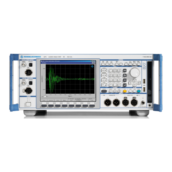
Windows Explorer® is assumed and, therefore, not discussed in any detail. The R&S UPV audio analyzer can be fully operated via the controls on the front panel. It is, however, also possible to operate the instrument using an external keyboard and mouse. - Page 24 ® Startup R&S Description of Front View Fig. 2-1: Front Panel R&S UPV Fig. 2-2: Front Panel R&S UPV66 2.1.1 Screen with softkeys The large screen shows all of the important settings and states of the audio analyzer in a clearly organized display. 5 displays ("screens") are provided to ensure clearer organization of the many possible panels and display windows.
- Page 25 It otherwise remains hidden in order to save space. In the operating and display area ● - the Audio Analyzer R&S UPV is operated using numerous panels which can be selected by the user ●...
-
Page 26: Navigation Keys
® Startup R&S Description of Front View The softkeys ● corresponds to the label on the softkey bar and WINBAR. The softkeys can also be operated using the function keys on the external keyboard or by clicking the asso- ciated button. 2.1.2 Navigation keys The navigation keys consist of 4 rocker buttons that are used for switching forward and back:... -
Page 27: Control Panel
Window", on page 202), provided that it appears in the R&S UPV style. The appearance of the file selector can be changed via the Config panel under the "File Selector" heading. To switch on the R&S UPV style, the "Win Style" checkmark must not be set (see chapter 4.15.1,... - Page 28 ® Startup R&S Description of Front View ● Adjusting the loudspeaker ● Printing out the screen contents ● Shutting down the operating system ● Switch between remote / manual operation ● Switch off outputs START Starts continuous measurements and sweeps (the LED is on); resets Min/Max values for bargraph displays, averaging for measurement results, and limit overshoots SINGLE Starts a single measurement or a single sweep (the LED is on during execution)
- Page 29 ® Startup R&S Description of Front View 2.1.5 VARIATION panel Rotary Knob Moves the focus in the panels, selection windows and tables Varies the entry value at the cursor position Moves the active cursor in the graphical windows Pressing the rotary knob has the same effect as pressing the ENTER key CURSOR UP / DOWN Move the focus in the panels, selection windows and tables Varies the entry value at the cursor position...
-
Page 30: Headphone Connector
Description of Front View 2.1.7 CD/DVD Combo drive The integrated combined CD/DVD drive is used to ● install software updates on the R&S UPV ● install sequence programs and macros ● import data and instrument settings from other R&S UPVs ●... - Page 31 Loads the factory default settings of the instrument or carries out a Master PRESET. ● Factory setting: Pressing the button briefly displays the security prompt "Do you want to preset the UPV?". If you answer this question with "Yes", the factory default settings are restored immediately. ● Master PRESET:...
- Page 32 2.1.12 Digital Audio Interfaces Inputs and outputs for connecting digital consumer instruments and professional studio equipment. Requires the R&S UPV‑B2 option (digital audio interfaces) Getting Started 1146.2078.62 ─ 09...
-
Page 33: Power Switch
Risk of data loss There is a risk of data loss if the R&S UPV is switched off without first shutting down the operating system. It is urgently recommended to shut down the operating system before switching off the instrument (SHUT-DOWN key or via mouse operation). -
Page 34: Description Of The Rear Panel
The low-impedance input resistors (300 Ohm or 600 Ohm) are overloaded and have been switched off. UNBAL BNC sockets 2.2 Description of the Rear Panel This section provides an overview of the ports on the rear panel of the R&S UPV / R&S UPV66. Getting Started 1146.2078.62 ─ 09... - Page 35 Startup R&S Description of the Rear Panel 2.2.1 Remote control connectors USB IN USB device socket for remote operation of the audio analyzer (with the R&S UPV‑K4 option) LAN interface for ● Integration of the audio analyzer in a network ●...
- Page 36 R&S UPV via the RS 232‑C interface. Parallel printer interface, 25-pin D-Sub socket (not with internal control computer FMR9. For R&S UPV, the FMR9 is installed for serial number 103000 or higher; for R&S UPV‑66, it is installed for serial number 101000 or higher; see chapter 2.6.1,...
- Page 37 Output for the analog generator signal via an integrated amplifier for the direct actuation of small loudspeakers 2.2.6 Digital synchronization and expansion interfaces Inputs and outputs for reference and sync signals for the R&S UPV‑B2 option (digital audio interfaces) Getting Started 1146.2078.62 ─ 09...
- Page 38 AUX IN Input for a digital audio reference signal (DARS) AUX OUT Output for a digital audio reference signal (DARS) generated by the R&S UPV 2.2.7 IEC/IEEE-bus socket IEC bus socket (IEC 625/IEEE 488) for remote control of the R&S UPV Note Requires the R&S UPV‑K4 option (remote control).
- Page 39 If both slots are occupied by the UPV-B48, 16 analog input channels are available. The left plug-in slot at the rear panel of the R&S UPV is designated as Slot 1, and the right one as Slot 2. The installation manual included with the option refers to this desig- nation.
- Page 40 ® Startup R&S Description of the Rear Panel I²S 25-contact D-Sub connector for connecting the input and output lines of the I²S interfa- ces. The interface assignment is described in Chapter 4. To connect the DUT, use a well-shielded cable. TX CLK IN Additional BNC connector for connecting an external master clock signal.
-
Page 41: Putting Into Operation
® Startup R&S Putting into Operation 2.3 Putting into Operation The following section describes how to put the instrument into operation, connect external devices such as printer and monitor, and a connection of the audio analyzer with a network. It contains general safety instructions for instrument operation. For information about installing options, see chapter 2.9, "Installing Options",... -
Page 42: Setting Up The Instrument
® Startup R&S Putting into Operation 2.3.2 Setting Up the Instrument The instrument is intended for indoor use. It can either be set up as a separate unit or mounted in a 19" rack. The following ambient conditions at the location must be ensured: ●... - Page 43 Putting into Operation 2.3.2.1 Separate installation The R&S UPV can be set up on a level surface in horizontal position and with unfolded instrument feet. Risk of injury with unfolded instrument feet The instrument feet can suddenly fold back if the instrument is being moved or the feet are not completely folded out.
- Page 44 ® Startup R&S Putting into Operation 2.3.3 Connecting the R&S UPV to the AC Supply Possible damage to the instrument Before connecting and switching on the instrument, observe the following items to avoid any damage to the instrument: ● The tube for the housing has to be attached and screwed in place.
- Page 45 4. Close the flap. The R&S audio analyzer UPV is operated with the same AC fuses for all specified rated AC supply voltages. The precise designation of the fuses is indicated on the rear of the instrument.
- Page 46 2.3.3.4 Restarting the R&S UPV If the R&S UPV firmware was closed without shutting down the operating system (e.g. by clicking on the icon in the title bar or ALT F4 on the keyboard), the program can be restarted with the mouse in two ways: ●...
- Page 47 Switching Off Risk of data loss There is a risk of data loss if the R&S UPV is shut down without shutting down the operating system first. This may cause trouble during the boot process the next time the instrument is switched on.
-
Page 48: Function Check
® Startup R&S Function Check 3. Press the POWER switch on the front of the instrument. The instrument is disconnected from the AC supply, and power is removed from all modules. For remote control, you can also shut down the operating system by using the SYSTem:SHUTdown SCPI command. -
Page 49: Windows Operating System
"Start – Control Panel" (see the description of Windows and the hardware for information on the necessary settings). The R&S UPV does not feature a diskette drive. Data is exchanged using a USB stick which is inserted into one of the USB interfaces. - Page 50 System The function of some interfaces depends on which internal computer hardware the R&S UPV has been equipped with. This description makes reference to the computer hardware at some points. With firmware versions 3.x and older, the Windows ver- sion and the computer hardware information can be retrieved as follows: Call up the system settings under Windows via the menu "Start –...
-
Page 51: Connecting External Keyboard And Mouse
Windows key on the external keyboard. 2.7.2 Connecting an External Mouse The R&S UPV allows connecting a commercially available mouse with USB interface. The mouse makes it easier to move and resize the panels / graphical windows on the screen and provides alternative operating modes. - Page 52 2. Connect the external monitor, keyboard and mouse. 3. Switch on R&S UPV. 4. After starting the R&S UPV, exit or minimize the UPV program by clicking on the buttons on the right in the title bar. 5. Right-click on the desktop to open the following context menu.
- Page 53 ® Startup R&S Connecting an External Monitor 6. Select "Graphics properties…". 7. Click on the "Monitor" icon. 8. Place the focus on the "True Color" field. 9. Select the hidden button (press the TAB key three times, then press the spacebar and click the "Apply"...
- Page 54 15. Click "OK" to confirm the change, and then click "OK" again to close the window. Resetting the External Monitor to a Resolution of 800 x 600 Pixels The external monitor, mouse and keyboard are connected to the R&S UPV, the R&S UPV is switched on.
- Page 55 ® Startup R&S Connecting an External Monitor 3. Select "Graphics properties…". 4. Click on the "Twin View" icon. 5. Place the focus on the "Monitor" field as shown in the figure below. Getting Started 1146.2078.62 ─ 09...
- Page 56 2. Connect the external monitor, keyboard and mouse. 3. Switch on R&S UPV. 4. After starting the R&S UPV, exit or minimize the UPV program by clicking on the buttons on the right in the title bar. 5. Right-click on the desktop to open the following context menu.
- Page 57 ® Startup R&S Connecting an External Monitor 6. Select "Monitor". Switch off the internal LC screen and switch on the external monitor if it was previ- ously switched off. You can now set the external monitor to a resolution higher than 800 x 600 pixels. 7.
- Page 58 11. Click "OK" to confirm the change, and then click "OK" again to close the window. Resetting the External Monitor to a Resolution of 800 x 600 Pixels The external monitor, mouse and keyboard are connected to the R&S UPV, the R&S UPV is switched on.
- Page 59 2. Connect the external monitor, keyboard and mouse. 3. Switch on R&S UPV. 4. After starting the R&S UPV, exit or minimize the UPV program by clicking on the buttons on the right in the title bar. 5. Right-click on the desktop to open the following context menu.
- Page 60 ® Startup R&S Connecting an External Monitor 6. Select "Monitor". Switch off the internal LC screen and switch on the external monitor if it was previ- ously switched off. You can now set the external monitor to a resolution higher than 800 x 600 pixels. 7.
- Page 61 Connecting an External Monitor Resetting the External Monitor to a Resolution of 800 x 600 Pixels The external monitor, mouse and keyboard are connected to the R&S UPV, the R&S UPV is switched on. 1. Exit or minimize the UPV program by clicking on the buttons on the right in the title bar.
- Page 62 2. Connect the external monitor, keyboard and mouse. 3. Switch on R&S UPV. 4. After starting the R&S UPV, exit or minimize the UPV program by clicking on the buttons on the right in the title bar. 5. Right-click on the desktop to open the following context menu.
- Page 63 ® Startup R&S Connecting an External Monitor 6. Select "Digital Display". Switch off the internal LC screen and switch on the external monitor if it was previ- ously switched off. You can now set the external monitor to a resolution higher than 800 x 600 pixels. 7.
- Page 64 Connecting an External Monitor Resetting the External Monitor to a Resolution of 800 x 600 Pixels The external monitor, mouse and keyboard are connected to the R&S UPV, the R&S UPV is switched on. 1. Exit or minimize the UPV program by clicking on the buttons on the right in the title bar.
- Page 65 Before March 2008: You can switch on the internal display by using the key combina- tion CTRL + ALT + F4 on an external keyboard. Since March 2008, the R&S UPV has been shipped with a new LCD that can be switched on using the shortcut CTRL + ALT + F3.
- Page 66 2. Connect the external monitor, keyboard and mouse. 3. Switch on R&S UPV. 4. After starting the R&S UPV, exit or minimize the UPV program by clicking on the buttons on the right in the title bar. 5. Right‑click the desktop to open the context menu and then select "Graphics Options"...
-
Page 67: Installing Options
Monitor" for an external monitor at the VGA port or "Built-in Display + Digital Dis- play" for the DVI‑D port. The internal screen and the external screen are switched 2.9 Installing Options The R&S UPV can be equipped with a few options. These options can be divided into two basic categories: Software options These can be installed by the user alone;... - Page 68 In this case, a unique computer name is used for identification in the network. Every R&S UPV is assigned an individual computer name at the factory. This name can be queried in the Windows menu "Start - My Computer" and changed (see chap- ter 2.10.2.3, "Querying the computer...
- Page 69 53). Point-to-point connections To set up a simple network – a LAN connection between an R&S UPV and a computer without integration in a larger network – an IP address must be assigned for the R&S UPV and the computer. The IP addresses 192.168.xxx.yyy are available, whereby both xxx and yyy can have the values 1 to 254;...
- Page 70 ® Startup R&S Connect R&S UPV to a Network (LAN) 2. "Click on Network and Internet Connections" and then click on "Network Connec- tions" at the bottom right in this menu. 3. Right-click in the menu "Network Connections Local Area Connection" and then click on "Properties".
- Page 71 ® Startup R&S Connect R&S UPV to a Network (LAN) 5. In the "Internet Protocol (TCP/IP) Properties" menu, enter the IP address in the "Use the following IP address" field (the complete data are available from the net- work administrator). Complete the entry with "OK" in all menus.
- Page 72 Access from R&S UPV to the hard disk of a computer that is also connected to the net- work can, however, be performed relatively easy. The directory which the R&S UPV is to access simply has to be enabled on the remote computer.
- Page 73 The PC is listed with its computer name as the search result. 4. Click on the computer name. The enabled directory is displayed and the files stored in it can be used in the R&S UPV. Note: If a user name and password are requested when you click the computer, the login name and password used on the computer must be entered.
- Page 74 ® Startup R&S Connect R&S UPV to a Network (LAN) main tool for this configuration method is a browser, such as Microsoft Internet Explorer, but it is also possible to use other browsers such as Firefox or Netscape. 2.10.3.1 LXI classes and LXI functionality...
- Page 75 ® Startup R&S Connect R&S UPV to a Network (LAN) ● LAN LED off – The instrument does not have valid IP address. This may be due to one of the following reasons: 1) the instrument is configured with DHCP, but no DHCP router is connected,...
- Page 76 ® Startup R&S Connect R&S UPV to a Network (LAN) More information about the LXI standard is located on the LXI website under http://www.lxistandard.org or in the article about LXI in "News from Rohde & Schwarz, 2006/II - 190". 2.10.3.4...
- Page 77 ® Startup R&S Connect R&S UPV to a Network (LAN) to quickly identify an instrument that is mounted together with several other instru- ments of the same type, such as in a 19" rack. Clicking on "ACTIVE (press to toggle)" switches the flashing state off again.
- Page 78 ® Startup R&S Connect R&S UPV to a Network (LAN) Switching from DHCP enabled mode to manual configuration mode may trigger an instrument restart when the new setting is confirmed (depends on the configuration). If incorrect network configuration settings have been entered, LAN RESET on the rear panel of the instrument must be used to restore access to the Web interface.
- Page 79 ® Startup R&S Connect R&S UPV to a Network (LAN) ● ICMP Ping – ICMP Ping must be enabled to use the ping utility. ● VXI-11 Discovery – Enables or prevents discovering the instrument via the VXI-11 Discovery proto- col, which is a protocol jointly developed by National Instruments and VISA for searching for devices on a LAN.
- Page 80 Connect R&S UPV to a Network (LAN) 2.10.4 Configuration for manual remote operation The R&S UPV can be operated manually from an external computer via a network con- nection. The Windows program Remote Desktop Connection is used for operation, see chapter 4.16, "Manual Remote...
- Page 81 ® Startup R&S Connect R&S UPV to a Network (LAN) 2.10.4.2 Starting manual remote operation at the external computer The Remote Desktop Connection program is already installed in the Windows operat- ing system (program name "mstsc.exe" in "C:\Windows\System32"). . For all other Windows operating systems from Windows 95 and higher, the program can be down- loaded free-of-charge from the Internet (http://www.microsoft.com).
- Page 82 R&S UPV must be entered on the external computer. The instrument ID - the com- puter name of R&S UPV - identify the R&S UPV in the network. Every R&S UPV is supplied together with a computer name which can be used for manual remote operation.
-
Page 83: Firmware Update
"Computer:" entry line. 5. 5. The resolution for the display of the R&S UPV monitor is set to 800 x 600 on the Display tab. 6. Establish the connection by clicking on the "Connect" button. -
Page 84: Windows Xp Recovery And Backup
Windows image program must be reloaded). 2.12 Windows XP Recovery and Backup The R&S UPV provides an invisible backup and recovery partition. A backup of the fac- tory system partition (C:\) is saved by default and can be restored in case of a sys- tem crash. - Page 85 For the R&S UPV, the use of an external keyboard is recommended. The operation is described with respect to an external keyboard. It is recommended to connect a mouse that allows an intuitive operation! During restore, the system partition (C:\) is deleted, formatted and rewritten.
- Page 86 5. Select "Exit and Shutdown" with the cursor keys. 6. Exit the program and shut down the R&S UPV with the ENTER key. 2.12.3 Restoring a Selected Version of the System Partition 1. Use the cursor keys to select "Restore Backup" in the "Windows XP Recovery and Backup Partition"...
- Page 87 6. Start the restore process with the ENTER key. The script that is performed during recovery is displayed. 7. After the restore, shut down and switch off the R&S UPV. The new setting is now active. 2.12.4 Recover Factory Default 1.
- Page 88 3. Select the "Restore now" button with the TAB keys. 4. Start the restore process with the ENTER key. The script that is performed during recovery is displayed. 5. After the restore, shut down and switch off the R&S UPV. The new setting is now active. 2.12.5 Deleting Backups Up to five backups in addition to the factory default can be stored on the recovery parti- tion.
-
Page 89: Windows 7 Recovery And Backup
The Windows XP Recovery and Backup Partition menu opens. 9. Select "Exit and Shutdown" with the cursor keys. 10. Exit the menu and shut down the R&S UPV by clicking on the ENTER key. 2.13 Windows 7 Recovery and Backup The R&S UPV provides an invisible backup and recovery partition. - Page 90 Windows XP, it can still be operated in the usual way using an external key- board. The figures below show the backup/recovery system for the R&S UPV. They are equally valid for the R&S UPP. The following window is displayed after every boot procedure. The user can choose between "Firmware"...
- Page 91 ® Startup R&S Windows 7 Recovery and Backup 2.13.2 Restoring Factory Default To restore the "Factory Default" state, select "Factory Default". Using the TAB keys, select "Restore Selected" and confirm with ENTER. 2.13.3 Restoring a "User Backup" To restore a different backup, choose the selection list using the Shift+TAB key combi- nation and select the desired backup using the "up/down"...
- Page 92 ® Startup R&S Windows 7 Recovery and Backup 3. Entries must be made in the "Name" and "Description" fields; the entries shown here are intended as examples only (the date and time are entered automatically). Select the "Start Backup" button using the TAB keys. 4.
- Page 93 ® Startup R&S Windows 7 Recovery and Backup 2.13.5 Deleting Backups Deleting factory default setting The factory default is treated in exactly the same way as a normal backup. Take care not to inadvertently delete the factory default! Using the TAB keys, select the backup to be deleted. Then select "Delete Selected" and confirm with ENTER.
- Page 94 ® Startup R&S Windows 7 Recovery and Backup Getting Started 1146.2078.62 ─ 09...
-
Page 95: Getting Started
Operation at the analog and digital interfaces is the same. The many available options mean that the R&S UPV can be adapted to perform a wide variety of different tasks. The basic version of the instrument has analog audio interfa- ces. - Page 96 3.2.2 Rapid Deactivation of Outputs The OUTPUT OFF key can be used in the event of faults to deactivate all outputs of the R&S UPV. The key affects all audio outputs, i.e. for both analog and digital audio signals. The deactivated lines can only be reactivated by pressing the OUTPUT OFF key again.
-
Page 97: Brief Introduction To Operation
3.3 Brief Introduction to Operation 3.3.1 Windows User Interface and Controls To provide the user with a familiar environment, operation of the R&S UPV is largely based on the Windows user interfaces. All panels, entry windows, etc. are made up of known elements. - Page 98 It is assumed that the user is familiar with these basic rules. This information is therefore not given in detail in this manual. The R&S UPV can for the most part be operated via the front panel. The instrument is operated using function keys with permanently assigned functions, softkeys with functions which vary depending on the application, and the rotary knob with integrated entry function.
- Page 99 ® Getting Started R&S Brief Introduction to Operation Fig. 3-1: Screen with the essential elements 1 = Panel 2 = Menu bar 3 = Numeric display 4 = Graphical window 5 = Hidden panels 6 = WINBAR 7 = Softkeys One of the two bars (either the softkey bar or the WINBAR) is always displayed at the bottom of the screen.
- Page 100 WINBAR. If a hidden panel is selected, it is redisplayed on the screen with its previously set size and position; it simultaneously receives the focus. 3.3.3 Panels and Display Windows The R&S UPV audio analyzer distinguishes between the following panels and display windows: ●...
- Page 101 Introduction Owing to the large number of measurement functions and setting options, beginners can often find the R&S UPV audio analyzer difficult to operate. The quickstart panel provides assistance – it allows the inexperienced user to specify the outputs and inputs to which he wants to connect his "device under test" and, in par- ticular, which audio measurement task he wants to carry out.
- Page 102 Getting Started R&S Brief Introduction to Operation As users become more familiar with the R&S UPV audio analyzer, they can use the expert icon to change over from the quickstart panel to the normal user interface of the audio analyzer in order to access the full range of functions.
- Page 103 R&S Brief Introduction to Operation The available selection depends on the R&S UPV audio analyzer and its options. The entries are self‑explanatory. Each time the generator output is changed, the combo box for selecting the desired measurement task (9) is reset (- - - - - -) and a new measurement task must be selected.
- Page 104 DUT, the measurement task "D/A Linearity" is not available as this is intended only for a digital output. Selection of a measurement task sets up the R&S UPV audio analyzer accordingly without further action being required. With some measurement tasks, the measure- ment must be started by clicking the "Start continuous measurement"...
- Page 105 R&S UPV audio analyzer, will result in inconsistencies between the set- tings in the quickstart panel and the actual setup of the R&S UPV audio analyzer; mak- ing subsequent settings outside the quickstart panel may, however, be necessary. The message "Operations outside Quickstart Panel detected! QSP display might be differ-...
- Page 106 Filter Definition of filter properties ● Auxiliaries Settings for integrated loudspeaker and connected headphones ● Settings for R&S UPV U2 BNC audio monitoring outputs ● Settings for auxiliary analog output ● Settings for trigger input and trigger output ● Operation of one or more R&S UPZ audio switchers Switcher Panel ●...
- Page 107 Bar Graph 1 to 2 ● Dig Analyzer Protocol The analyzed data of the digital audio protocol is displayed here (R&S UPV K21 option (digital audio protocol)) 3.3.6 Basic Rules of Operation The following basic rules are intended to simplify operation of the audio analyzer: ●...
- Page 108 ® Getting Started R&S Brief Introduction to Operation Panels can only be operated if they have the focus (indicated by the blue title bar). The simplest way of changing from one panel to another in the case of operation via the front panel is using the direction keys .
- Page 109 ® Getting Started R&S Brief Introduction to Operation Parameters are selected by highlighting the desired item and confirming with the ENTER key or a rotary-knob click. Items in the parameter list are highlighted using the rotary knob, the up/down cursor keys or the keys.
- Page 110 ® Getting Started R&S Brief Introduction to Operation It is also possible to enter the value in Direct mode. Changing to Direct mode is per- formed by pressing the ENTER key or with a rotary‑knob click; the color of the selec- tion frame then changes to magenta.
- Page 111 The keypad on the front panel of the R&S UPV is auto- matically switched to the mode for entering alphanumeric characters. Text is entered in...
- Page 112 ® Getting Started R&S Brief Introduction to Operation Range" field always refer to the highlighted parameter field. The valid value range is given in the unit currently selected. Entries outside the specified value range are not accepted; an audible warning is issued and the entry is changed to its permissible minimum or maximum value.
- Page 113 ® Getting Started R&S Brief Introduction to Operation 3.3.9.1 Numeric Display Field The numeric display field provides a clear overview of the numeric values from various analyzer functions and displays a maximum of 8 numeric value results from the "Ana- lyzer Function"...
- Page 114 ® Getting Started R&S Brief Introduction to Operation Configuring the Numeric Display Field and Combo Display The settings for the individual columns of the numeric display field or for the combo displays are made in the following four configuration panels which can be opened using the "DispConfig"...
-
Page 115: Introduction To Instrument Operation Using Examples
1. Step: Loading the factory settings The easiest way to load the factory settings of the instrument is to press the PRESET key on the front of the R&S UPV. Alternatively, the factory settings can be loaded by opening the menu bar with the MENU key, highlighting the "File"... - Page 116 ® Getting Started R&S Introduction to Instrument Operation Using Examples rotary-knob click, and then highlighting and activating "Preset (Load Default)" in the displayed list in the same way. 2. Step: Setting the required generator signal a) The basic settings for configuring the generator are made in the "Generator Config"...
- Page 117 ® Getting Started R&S Introduction to Instrument Operation Using Examples c) Next, the "Generator Function" panel must be activated again; press the WINDOW </> keys until the title bar of the panel is marked in blue. Sine-wave signals are required; this setting is already selected. To be able to measure the frequency response, the sine-wave signal must be swept in the frequency.
- Page 118 ® Getting Started R&S Introduction to Instrument Operation Using Examples The sweep variable must now be specified in the "X Axis" field. Frequency is already preset here (as required in this example). No other sweep variable is required; therefore, the "Z Axis" field also remains unchanged and set to "Off".
- Page 119 ® Getting Started R&S Introduction to Instrument Operation Using Examples The desired output voltage for the measurement is entered in the "Voltage" field; once again, the field must be highlighted before the value can be entered. The value range is again displayed above the softkeys and the available units are shown in the softkeys.
- Page 120 ® Getting Started R&S Introduction to Instrument Operation Using Examples b) If necessary, it is possible to toggle between AC and DC coupling using the two radio buttons. The fields for the measurement bandwidth are already preset with the appropri- ate setting;...
- Page 121 ® Getting Started R&S Introduction to Instrument Operation Using Examples c) The following are set in the Analyzer Function panel: ● what is measured (which measurement function) and ● how measurement is performed (which measurement method) The RMS value of the voltage must be measured for the frequency response measurement described here;...
- Page 122 ® Getting Started R&S Introduction to Instrument Operation Using Examples In the default instrument setup, the numeric measurement display is also already open. If the DUT is correctly connected to the audio analyzer, measured values will already be displayed. The panels for configuring the measured value display are used to determine how the measurement results are presented (i.e.
- Page 123 ® Getting Started R&S Introduction to Instrument Operation Using Examples a) The sweep is started by pressing the START key in the top right part of the front panel. The status message "Sweep Run Cont" informs the user that when this key is pressed the sweep will start and be repeated continuously.
- Page 124 Introduction to Instrument Operation Using Examples d) The traces can display the results of the different measurements available in the R&S UPV. For the frequency response measurement, the measurement results for the measurement function selected in the Function field in the Analyzer Function panel (here the RMS measurement) must be displayed graphically.
- Page 125 ® Getting Started R&S Introduction to Instrument Operation Using Examples h) The default settings for the x‑axis are also mostly correct for this example: By selecting a frequency sweep in the Generator Function panel, the x‑axis is automatically defined as the frequency axis with the unit Hz. If "Auto"...
- Page 126 This value must be replaced by the output voltage value of the DUT measured with the reference frequency of 1 kHz. The R&S UPV offers a very simple way of doing this: If the parameter list is opened in the "Reference" field, it is possible to select the setting "Ref 1000 Hz".
- Page 127 The desired file name can now be entered using the keypad on the front panel. The keypad on the front panel of the R&S UPV is automatically switched to the mode for entering alphanumeric characters. Text is entered in the same way as on cellphones: The characters assigned to a key are called up in sequence by repeatedly pressing the corresponding key.
- Page 128 ® Getting Started R&S Introduction to Instrument Operation Using Examples a) The easiest way to load the factory settings of the instrument is to press the PRESET key on the front panel. Alternatively, the default setup can also be loaded via the menu bar. 2.
- Page 129 ® Getting Started R&S Introduction to Instrument Operation Using Examples 3. Step: Selection of required measurement a) The basic settings for configuring the analyzer are again made in the "Analyzer Config" panel. These settings are made in the same way as shown in the previous example. b) Next, the "Analyzer Function"...
- Page 130 ® Getting Started R&S Introduction to Instrument Operation Using Examples e) The calculation for harmonics and noise components can, if necessary, be restricted to within band limits which can be entered in the two fields "Freq Lim Low" and "Freq Lim Upp". All other parameter fields are not relevant for this example.
- Page 131 ® Getting Started R&S Introduction to Instrument Operation Using Examples a) In the "Analyzer Function" panel already used for configuring the THD+N mea- surement, an FFT analysis to be performed following the measurement can be set after the actual measurement function has been selected. To do this, activate the "Post FFT"...
- Page 132 ® Getting Started R&S Introduction to Instrument Operation Using Examples d) The associated graphical window can be opened using the "Show" button in the "Display" field. The window appears in the same screen so that the effect of the following settings can be observed directly. e) In each FFT window, one or two traces (Trace A and Trace B) can be plotted on the frequency axis.
- Page 133 ® Getting Started R&S Introduction to Instrument Operation Using Examples h) The spectral display of the output signal with its harmonics may now look like the example shown below. 6. Step: Evaluating the graphic with cursors and markers All graphical displays can be evaluated using horizontal and vertical cursors; the X and Y-values shown in the display fields associated with the cursors are always current values.
- Page 134 ® Getting Started R&S Introduction to Instrument Operation Using Examples a) Setting markers: Pressing the "Marker" button calls up the Marker softkeys which are used in this example to first select Trace A so that markers can be set. The next softkey level appears simultaneously: The "Track to Max"...
-
Page 135: Loading Predefined Instrument Setups
Many of these example measurements (essentially those at the analog interfaces) can be performed using the basic version of the audio analyzer. The R&S UPV-B2 (digital audio interfaces) or R&S UPV-B20 option is required for all measurements at the digi- tal interfaces. - Page 136 ® Getting Started R&S Loading Predefined Instrument Setups Alternatively, the file window used to select the example measurements can also be opened using the LOAD key on the front; in this case, however, the appropriate directories must be selected manually. All of the setups listed here use the same basic settings.
-
Page 137: Manual Operation
The clearly organized display shows the current state of the audio analyzer. The R&S UPV model can be fully operated using the control elements on the front panel; additional peripherals such as a mouse and keyboard are not essential require- ments. -
Page 138: Functional Division Of The Audio Analyzer
AES/EBU and SPDIF inter- faces and at optical interfaces. The R&S UPV-B4x options, which can be installed in the expansion slots at the rear of the instrument, provide further interfaces for outputting test signals. - Page 139 Functional Division of the Audio Analyzer ent signals to be output on the two analog output channels. With all the digital genera- tor options (R&S UPV-B2, -B20, -B41 (I²S interface) or -B42 (universal serial interface), two different signals are also available at the digital outputs.
- Page 140 4.2.3 Analyzers The R&S UPV performs all measurements using digital signal processing. Here, ana- log signals to be measured are first subjected to complex 2-channel analog prepro- cessing on analog measurement modules before they are digitized and fed to the digi- tal measurement routines.
- Page 141 With the R&S UPV-B2 (digital audio interfaces) option (or R&S UPV-B20), digital audio data streams can also be measured at AES/EBU or SPDIF interfaces. The R&S UPV-B4x options, which can be installed in the expansion slots at the rear of the instrument, provide further interfaces for analyzing signals in other formats.
- Page 142 The type of display, the units used, scaling, etc., can be set differently for each measurement function in the associated panels. The diagram below shows the function blocks and the analysis levels of the R&S UPV: Similar to the generator component, the analyzer component is operated in two stages: 1.
- Page 143 ® Manual Operation R&S Functional Division of the Audio Analyzer 2. In the second step, the measurements are set at the various analysis levels in the "Analyzer Function" panel. The measurements are set in the order of their importance: ● Measurements at the function level, e.g.
- Page 144 ® Manual Operation R&S Functional Division of the Audio Analyzer 3. If audio monitoring using the integrated loudspeaker or with headphones is required, this is set in the "Auxiliaries" panel. Getting Started 1146.2078.62 ─ 09...
-
Page 145: General Information On Operation
® Manual Operation R&S General Information on Operation 4. The following settings can be made in other panels: ● the way in which the measurement results are to be displayed (numerically or graphically) ● scaling ● limit monitoring ● minimum and/or maximum values ●... - Page 146 4.3.3 Operation Using the Mouse Similar to other Windows® programs, the R&S UPV can also be operated with a mouse. To permit this, a commercially available mouse (not supplied with the instru- ment) is connected to one of the four USB interfaces at the front or rear of the instru- ment (see chapter 2.7.2, "Connecting an External...
- Page 147 ® Manual Operation R&S General Information on Operation 4.3.4 Operation Using an External Computer Keyboard A commercially available, external computer keyboard (not part of the scope of deliver- ies and services) can be connected to one of the four USB interfaces at the front or rear of the instrument (see chapter 2.7.1, "Connecting an External Keyboard.",...
-
Page 148: The Display
4.4.1 The Screens Five display windows (or "screens") are provided so that the wealth of information can be better organized. Fig. 4-1: R&S UPV display with its 5 screens 1 = Numeric display 2 = Panel 3 = Graphical window... - Page 149 ® Manual Operation R&S The Display ● Using the PC keyboard using the shortcuts CTRL + PAGE UP or CTRL + PAGE DOWN ● First open the menu bar at the top of the display with the mouse, then click on the Screen button and finally select the desired screen.
- Page 150 ® Manual Operation R&S The Display Softkeys with an additional checkbox are also used for a number of applications. In the example below, the left-hand softkey F5 can be used to activate and deactivate the X cursor in a curve diagram. The other softkeys are used to make other settings affecting this cursor.
- Page 151 ® Manual Operation R&S The Display Function Front panel PC keyboard Mouse Select softkey function Press softkey. Press keys F5 to F12. Click button of associ- ated softkey. 4.4.3 Moving and Resizing Panels and Graphical Windows As soon as a panel or display window has the focus, it becomes active and can be moved around the screen or resized.
- Page 152 ® Manual Operation R&S The Display When the "Vert Size" button is selected, the rotary knob can be used to resize the panel/window (the bottom edge of the selected panel is moved). When all modifications to the panel have been made, pressing the MODIFY key restores the original operating mode.
- Page 153 4.4.4.1 Status Displays The status of the R&S UPV is continuously displayed for the generator, analyzer, sweep system and other instrument states at the bottom of the screen above the four right-hand softkeys. Status displays always appear at the same position; they are assigned to the fields above the softkeys as shown below.
-
Page 154: Panels
® Manual Operation R&S Panels 4.4.4.3 Notes Information concerning the panel settings and so on is also given at the bottom of the screen above the softkey bar (only the space above the four left-hand softkeys is used). 4.4.4.4 Warnings If the user attempts to make measurement settings which conflict with the usual test specifications, warnings appear on the screen;... - Page 155 Measured value lists, in which the measured values are listed in tabular form; this also includes the "Dig Analyzer Protocol", in which the values of the protocol data of a digital audio data stream are displayed (R&S UPV-K21 option (digital audio protocol)).
- Page 156 ® Manual Operation R&S Panels The table below shows the alternative operating modes for mouse and external key- board: Function Front panel PC keyboard Mouse Open panel Press the MENU key Press the shortcut CTRL Open the menu bar by and highlight the "Instru- + M, then highlight moving to left edge of...
- Page 157 ® Manual Operation R&S Panels Panels consist of up to three columns, depending on the function block on which the panel is based. For example, two-channel functions are operated in panels with two columns. When defining graphical windows, settings from Trace 1 can be applied to Trace 2 in a third column between the two original columns so that trace 2 does not have to be configured separately.
- Page 158 ® Manual Operation R&S Panels An alphanumeric value (e.g. label text) can be entered in this field. ● Button Buttons are used to trigger actions; here, for example, to display a measurement graph. ● Checkbox If a checkbox is activated, the assigned setting is selected or enabled. ●...
- Page 159 ® Manual Operation R&S Panels With multi-column panels, settings can be transferred from the left-hand to the right-hand column without the parameter having to be entered a second time. If the track box is activated, all of the settings within the function group apply to both col- umns.
-
Page 160: Settings On The Audio Analyzer
Some keys on the front panel of the R&S UPV directly initiate a setting, e.g. the OUTPUT OFF key switches the outputs off or on again. An overview showing the func- tion of all keys can be found at the end of this chapter (see chapter 4.18, "Overview of... -
Page 161: Settings In The Panels
R&S Settings in the Panels The R&S UPV is equipped with the Windows XP operating system. Settings at system level are only rarely required, e.g. installation of a new printer driver. Connecting a key- board and mouse makes Windows easier to use. - Page 162 Each of these interfaces determines the basic characteristics of the instru- ment, whereby these characteristics are separate for generator and analyzer. These interface characteristics define quasi-independent instruments within the R&S UPV. The settings for these instruments are made in the selection field in the first field of the "Generator Config"...
- Page 163 4.7.4 Hiding Parameter Fields The R&S UPV always attempts to keep the panels as short as possible. For this rea- son, unneeded fields are hidden.
- Page 164 ® Manual Operation R&S Settings in the Panels 4.7.5 Highlighting Controls A control element is always selected in the same way, regardless of whether it is a checkbox, radio button, entry field and so on. A control element is activated by shifting the focus to this element. The entry focus is indicated by a blue, green or magenta border.
- Page 165 ® Manual Operation R&S Settings in the Panels Function Front panel Computer keyboard Mouse Toggle Highlight the desired ele- Highlight the desired ele- Click the desired radio ment with the rotary ment with the cursor button. knob or cursor keys, keys, Switch the function with Toggle the function with...
- Page 166 ® Manual Operation R&S Settings in the Panels Function Front panel Computer keyboard Mouse Open parameter list Rotary-knob click or Press the Enter key. Click button. press the ENTER key. Scroll Move the displayed sec- Move the displayed sec- Activate the UP or tion of the list using the tion of the list using the DOWN button in the...
- Page 167 ® Manual Operation R&S Settings in the Panels ● The old value is retained. ● Softkeys The selected unit is set and adopted together with the newly entered value. ● "m" or "k" on the external keyboard The number entry can also be completed with the entry of the unit. Simply entering values such as "m"...
- Page 168 (defined in the test speci- fications) below this full-scale level. It should be noted, however, that the maximum values of the R&S UPV cannot be exceeded, both for system reasons and due to the "Max Voltage" setting.
- Page 169 ® Manual Operation R&S Settings in the Panels Function Front panel Computer keyboard Mouse Entering a new value: Highlight the numeric Highlight the numeric entry field and enter the entry field and enter the (Edit mode) new value directly using new value directly using the numeric keypad.
- Page 170 The keypad on the front panel of the R&S UPV is auto- matically switched to the mode for entering alphanumeric characters. Text is entered in the same way as on cellphones: Repeatedly pressing a key calls up the characters assigned to the corresponding key in sequence.
- Page 171 ESC – The old text is retained. Whenever files stored on the R&S UPV are to be called up, e.g. to load saved scans in a diagram, or special functions are to be adopted from files, etc., a text entry field also appears.
- Page 172 In many cases, settings are to apply e.g. to both measurement channels or to both traces. Here the R&S UPV provides multi-column panels which allow settings to be transferred from the left-hand to the right-hand column without the parameter having to be entered a second time.
- Page 173 Settings in the Panels 4.7.14 Completing Settings For the entry of numeric values, the R&S UPV distinguishes between Edit mode (iden- tified by a green selection frame) and Direct mode (identified by a magenta selection frame). See also the section chapter 4.7.9, "Numeric Entries –...
-
Page 174: Measurement Displays
® Manual Operation R&S Measurement Displays Function Front panel Computer keyboard Mouse Varying numeric values Highlight the numeric Highlight the numeric with immediate adoption entry field, switch to entry field, switch to by hardware Direct mode with a Direct mode with the rotary-knob click;... - Page 175 ® Manual Operation R&S Measurement Displays played as digital numeric values, in analog bar graphs, in result graphics or in data lists. The user can open any number of measurement windows on the screen. The size of the panels can be changed within broad limits, whereby the font size, scaling and so on are adapted automatically;...
- Page 176 ® Manual Operation R&S Measurement Displays lyzer Function" panel. The individual columns are permanently assigned, from left to right: ● Column 1: Measurement results of the function which is set in the "Analyzer Function" panel in the "Function" field. ● Column 2: Measurement results for the set "Level Monitor"...
- Page 177 The combo display is used for this purpose. Additional information can be displayed for every measurement shown in the numeric display. The free selection and free scalability mean that especially important or critical results can be monitored and tracked even when viewing the R&S UPV screen from a rela- tively long distance. 4.8.3.1...
- Page 178 ® Manual Operation R&S Measurement Displays Alternatively, combo displays can also be opened via the corresponding configuration panels. The associated combo display is activated using the "Show" button in the "Dis- play" field. The combo displays can also be opened via the menu bar: They are located under the "Displays"...
- Page 179 ® Manual Operation R&S Measurement Displays Function Front panel PC keyboard Mouse Activating a Combo Dis- Highlight the desired Select the numeric mea- Double-click desired play via a Numeric Dis- measurement display in surement display with measurement display in play Field the numeric display field CTRL+TAB or CTRL numeric display field.
- Page 180 ® Manual Operation R&S Measurement Displays Function Front panel PC keyboard Mouse Open panel for configur- Press the MENU key Press shortcut CTRL + Move the mouse pointer ing combined field or and highlight the Disp M, then highlight Disp to the left edge of the numeric display field Config button with the...
- Page 181 ® Manual Operation R&S Measurement Displays An overview with all the units that occur for the audio analyzer and their conversion formulas is located in chapter 4.17, "Units", on page 207. Details concerning the numeric value display can be specified here for all linear units.
- Page 182 ® Manual Operation R&S Measurement Displays ● Limits A lower and/or upper limit can be defined for each measurement result. If the limit is activated, each measured value is compared with the limit. The set limits are shown in the bottom part of the combined display and appear as a red limit marking on the bar graph.
- Page 183 ® Manual Operation R&S Measurement Displays Pressing the START key again resets the Min/Max values. ● Number of displayed digits The "Resolution" field is used to set the number of digits used when displaying the measured values, Min/Max values and limits. Values in linear units can be displayed with 3 to 7 digits;...
- Page 184 ® Manual Operation R&S Measurement Displays 4.8.4.1 Sweep graph Here, the measured values of a measurement sequence (sweep) can be displayed as a line diagram in a coordinate system. One or two traces (TRACE A and TRACE B) can be recorded along an x-axis. Each trace can consist of a large number of scans. The traces can be saved and saved traces, reference curves and/or limit curves can be imported into the graph.
- Page 185 ® Manual Operation R&S Measurement Displays 4.8.4.2 FFT Graph In these panels, the frequency spectrum of the FFT measurement function or the Post FFT downstream of another measurement function. One or two traces (TRACE A and TRACE B) can be recorded along a frequency axis. Each trace can consist of a large number of scans.
- Page 186 ® Manual Operation R&S Measurement Displays 4.8.4.3 Waveform The waveform display is a type of oscillogram in which the signal characteristic of the analyzed audio signal over time is displayed. One or two traces (TRACE A and TRACE B) can be recorded along a time axis. The traces can be saved and saved traces, ref- erence curves and/or limit curves can be imported into the graph.
- Page 187 ® Manual Operation R&S Measurement Displays 4.8.4.4 Bar Graph If one of the functions "THD", "Mod Dist", "DFD" or "DIM" is selected in the "Analyzer Function" panel, the function measurement result can be displayed broken down into its frequency components on a bar graph. The individual distortion products are recor- ded along a frequency axis.
- Page 188 ® Manual Operation R&S Measurement Displays 4.8.4.5 PESQ/POLQA Graph In these graphics windows, you can display the PESQ and MOS value of the PESQ/ POLQA measurement as well as the time delay between the reference and measure- ment signal over a time axis. It is possible to display up to two PESQ/POLQA graphs simultaneously, where they can be configured differently.
- Page 189 ® Manual Operation R&S Measurement Displays In the "Analyzer Function" panel, it is also possible to use the "Show" button to open some graphical or data windows. They will then be displayed in the same screen, with- out opening the associated configuration panels. Function Front panel PC keyboard...
- Page 190 ® Manual Operation R&S Measurement Displays Function Front panel PC keyboard Mouse Open panel for configur- Press the MENU key Press shortcut CTRL + Open the menu bar by ing a graphical window and highlight the M, then highlight the moving to the left edge "Disp Config"...
- Page 191 ® Manual Operation R&S Measurement Displays Settings for the y-axis All the panels used for configuring graphical windows have three columns. In all graphical windows, two traces (TRACE A and TRACE B) can be recorded on y- axes along an x-axis. The "Y-Source" parameter field is used to determine which mea- surement functions are mapped to the y-axes.
- Page 192 ® Manual Operation R&S Measurement Displays Units of Measured Values This parameter field is used to set the unit for the trace. The units available in the parameter list depend in the type of measurement. Alternatively, if the checkbox is selected, the unit used in the analyzer will be used. An overview with all the units that occur for the audio analyzer and their conversion for- mulas is located in chapter 4.17,...
- Page 193 ® Manual Operation R&S Measurement Displays Main gridlines which are labeled with the associated numeric values can be added with different intervals. Subgridlines are used for further subdivisions; these lines are not labeled. Limits A lower and/or upper limit can be defined for each measurement result. If the limit is activated, each measured value is compared with the limit.
- Page 194 ® Manual Operation R&S Measurement Displays Extreme values If this checkbox is activated, a Min and Max characteristic is displayed that indicates the lowest and highest measurement results of a measuring sequence. Two additional gray lines which represent the measured extreme values (see the example above) then appear in the graph.
- Page 195 ® Manual Operation R&S Measurement Displays Markers are used to identify important measurement points. The cursors and markers can only be operated using the softkey bar; the softkeys can be operated from the front panel, using the keys F5 to F12 on the external PC key- board or by clicking with the mouse.
- Page 196 ® Manual Operation R&S Measurement Displays Scaling graph – Autoscale function Activating the "Autoscale" button opens another softkey level. The softkeys available here are used to rescale the selected axes (if required, it is also possible to rescale the axes for certain traces only). The action triggered with these buttons corresponds to that of the "Auto Scale"...
- Page 197 ® Manual Operation R&S Measurement Displays The two buttons "O Vert A" or "O Vert B" activate vertical cursors and place them on TRACE A or TRACE B. Both the cursor and its label fields are displayed in the color of the associated trace.
- Page 198 ® Manual Operation R&S Measurement Displays the measured values. If the number of recorded measurement points in the graph is greater than the number of pixels available for display, the largest measured value in each case is displayed at the corresponding pixel with X and Y value. ●...
- Page 199 ® Manual Operation R&S Measurement Displays graph), the cursor value is interpolated linearly at the pixels between the measured values. If the number of recorded measurement points in the graph is greater than the number of pixels available for display, the largest measured value in each case is displayed at the corresponding pixel with X and Y value.
- Page 200 ® Manual Operation R&S Measurement Displays In order to analyze individual scans with cursors, the cursor is switched to the desired scan in the following way: ● Front panel: with the keys ● External PC keyboard: with the keys ALT + PAGE UP and ALT + PAGE DOWN ●...
- Page 201 ® Manual Operation R&S Measurement Displays The "Act Curs In" button zooms in on the section of graph on either side of the active X-cursor. ● "Act Curs Out " The "Act Curs Out" button zooms out from the section of graph on either side of the active X-cursor.
- Page 202 ® Manual Operation R&S Measurement Displays Measured values which have violated the preset limits are displayed in red. In addition, a red arrow pointing up/down in the bottom right-hand corner of the graph provides a permanent indication of limit overranging/underranging. Restarting a continuous measurement with START and activating the "Restart Min/ Max, Lim Violation"...
- Page 203 ® Manual Operation R&S Measurement Displays Data list settings Function Front panel PC keyboard Mouse Open panel for configur- Press the MENU key Press shortcut CTRL + Open the menu bar by ing a data list and highlight the M, then highlight the moving to the left edge "Disp Config"...
-
Page 204: Settings In The Menu Bar
® Manual Operation R&S Settings in the Menu Bar Depending on the selected softkey, the following are listed in the data list: ● ● only the values which exceed the upper, lower or both limits ● only harmonics or ● only peaks Cursor in lists with several individual scans If a trace consists of several scans, only the values of one scan can be displayed in the... - Page 205 Settings", on page 204). ● Load Display Plug-in A plug-in can be selected here that expands the display options of UPV by addi- tional panels, e.g. a spectrogram representation. ● Print Preview A preview window of the current graphic is displayed here which is shown with the color profile configured for the respective output device.
- Page 206 ® Manual Operation R&S Settings in the Menu Bar Screens ● To select one of the five display options (screens), see chapter 4.4, "The Display", on page 132. Instruments To select the panels for configuring the generators, analyzers, filters and supplemen- tary functions.
- Page 207 ® Manual Operation R&S Settings in the Menu Bar ● In the list, open panels are displayed without a suffix, closed panels are identified by the suffix "closed", and open minimized panels by the suffix "hidden". Displays ● To select the measurement display windows. ●...
- Page 208 ® Manual Operation R&S Settings in the Menu Bar Utilities ● Diagnostic Panel Opens a panel for entering service settings ● Config panel Opens a panel for entering instrument-wide settings, e.g. IEC bus address, the appearance of the file select box or whether the menu bar or toolbar is perma- nently displayed on the monitor.
- Page 209 Utilities Config panel, General Configuration settings The R&S UPV allows you to have the menu bar and/or the toolbar displayed at the top edge or at the right-hand edge of the screen all the time. This feature is primarily for operation with the mouse.
-
Page 210: Settings On The Toolbar
These are mainly functions that are also available as keys on the front panel of the R&S UPV model. The symbols sim- plify operation with the mouse and can thus also be used with the R&S UPV66 model. -
Page 211: Settings In The Operating System
4.11 Settings in the Operating System The R&S UPV is equipped with the Windows XP operating system. Settings at system level are only rarely required, e.g. installation of a new printer driver. Connecting a keyboard and mouse makes Windows easier to use. -
Page 212: Auxiliaries Panel
● Audio Monitor, for configuring the audio-monitoring functions ● Analog Aux Output, the auxiliary analog output at the rear of the R&S UPV can be configured here ● Trigger Input / Output, for configuring the trigger inputs and outputs at the rear of the instrument 4.12.1 Audio Monitor Function... - Page 213 If "Both" is set, both chan- nels are separately available at the two headphone outputs; the loudspeaker outputs the signal from both channels. The same applies with installed R&S UPV-U2 retrofit for the two BNC sockets that are present.
-
Page 214: Rapid Deactivation Of Outputs
® Manual Operation R&S Rapid Deactivation of Outputs 4.12.2 Auxiliary analog output An auxiliary analog output, ANLG AUX OUT, for the following special applications is provided at the rear: ● Output of a DC signal, e.g. for supplying power to hearing aids ●... -
Page 215: Help System
In addition to the context-sensitive help, a compiled online help for all functions of the R&S UPV is provided on the supplied CD. This help can be called up on any computer using the Internet Explorer (version 4.0 and higher). - Page 216 ® Manual Operation R&S Help System ● "Find/Back" If you navigate in the online help by activating links, activating this button returns you to the previous page. ● "Scroll Left/Scroll Right" Sometimes the help pages are too wide to fit completely in the display. In this case, a horizontal scrollbar is displayed.
-
Page 217: File Management
Enter key. 4.15 File Management The R&S UPV uses files to store all instrument data, i.e. system and user data. User data includes stored instrument settings, data for equalizer files, lists for sweeps, and so on. The files are stored on the instrument's hard disk. The D:\ drive is available for storing user-defined data and can have any number of directory structures. - Page 218 ••• button in the respective panel and a File Select window appears. 4.15.1 Selecting the File Select Window In the R&S UPV, you can select between two fundamentally different types of "File Select" windows. The desired style can be defined in the menu bar under the button "Utilities", "Config Panel", section "General Configuration", parameter field"File Selec-...
- Page 219 The File Manager is used to perform general file management tasks, such as copying, moving, renaming and deleting files and creating new directories. This also allows sav- ing externally created files in the R&S UPV by copying them to the internal hard disk from a USB stick, a CD or a network.
- Page 220 Pressing these keys opens the "File Select" window. Every R&S UPV audio analyzer has a range of instrument settings which have been prepared by Rohde & Schwarz for a broad selection of typical measurements and which are available on the instrument as sample setups.
- Page 221 ® Manual Operation R&S File Management 4.15.5 List of File Extensions Used File type File Meaning exten- sion Instrument settings .SET Setup file for saving and loading the instrument parameters set by the user ("complete" setup) .SAC Setup file for saving and loading the instrument parameters set by the user ("current"...
-
Page 222: Manual Remote Operation
When establishing the connection, the instrument firmware at the R&S UPV is exited. During the manual remote control, it is not possible to perform any operations at the R&S UPV itself. Access by an external computer and the identity of the remote user is indicated on the login display of Windows. -
Page 223: Units
R&S Units To return to direct operation at the R&S UPV, it is necessary to log off the external user and log on the local user. The external user can be logged off at the external computer in the "Start" menu of the R&S UPV window by clicking on "Disconnect"... - Page 224 ® Manual Operation R&S Units 4.17.1.2 Units for digital level measurement results Basic unit: FS (Full Scale) *) Level measurement result in hex notation All digital analyzer measurement functions usually deliver values ranging from 0 to 1 FS values >1 may occur in the following cases: ●...
- Page 225 ® Manual Operation R&S Units 4.17.1.4 Unit for S/N measurement results 4.17.1.5 Units for frequency measurement results Basic unit: Hz 4.17.1.6 Units for phase measurement results Basic unit: ° (degrees) 4.17.1.7 Units for group delay measurement results Basic unit: s Getting Started 1146.2078.62 ─...
- Page 226 ® Manual Operation R&S Units 4.17.1.8 Units for digital jitter measurement results Basic unit: UI (unit interval) 4.17.1.9 Unit for digital phase measurement results (Phase to Ref) Basic unit: UI (unit interval) 4.17.2 Units for Value Entries To simplify matters: In the following conversion formulas, the entry values are designa- ted by the unit only.
- Page 227 ® Manual Operation R&S Units Relative analog level units (with reference) Absolute digital level units (without reference) Relative digital level units (with reference) Absolute time units Absolute frequency units Getting Started 1146.2078.62 ─ 09...
- Page 228 ® Manual Operation R&S Units Relative frequency units (with reference) Absolute phase units Deviations (tolerance) relative to previous measured values in settling function Step size of a logarithmic level sweep Absolute resistance unit Unit for jitter Getting Started 1146.2078.62 ─ 09...
-
Page 229: Overview Of Keys
® Manual Operation R&S Overview of Keys Unit for Phase to Ref 4.18 Overview of Keys The following table gives an overview of the key functions on the front panel. The table also gives the PC keyboard shortcuts which can be used to trigger the functions of the keys on the front of the instrument. - Page 230 ® Manual Operation R&S Overview of Keys Key on front panel Key of the PC keyboard Function Operation with mouse SHUT DOWN CTRL + F10 Stores the current settings on the hard disk and then shuts down the Windows® operating system LOCAL CTRL + F11 Switches the instrument from...
- Page 231 ® Manual Operation R&S Overview of Keys Table 4-5: VARIATION panel Key on front panel Key of the PC keyboard Function Operation with mouse MENU CTRL + M Displays the menu bar on the screen UNDO BACKSPACE Deletes the character to the left of the cursor Undoes the action last performed Closes the open panel;...
-
Page 232: Overview Of Panels And Measurement Displays (Graphical Windows)
® Manual Operation R&S Overview of Panels and Measurement Displays (Graphical Windows) Key on front panel Key of the PC keyboard Function Operation with mouse HIDE ALT + H Minimizes ("hides") the active panel or graphical window CLOSE ALT + C Closes the active panel or graphi- cal window HELP... - Page 233 R&S UPZ. ● Protocol Generator Settings for the generator functions for generating the digital audio protocol of the R&S UPV-K21 option (digital audio protocol). Panels which can be selected via the Disp Config menu bar button ● Function Config Settings for measured values of active measurement function in numeric dis- play field ●...
- Page 234 ® Manual Operation R&S Overview of Panels and Measurement Displays (Graphical Windows) ● PESQ/POLQA Graph Two of these panels are available, allowing you to display up to two PESQ/ 1…2 Config POLQA windows simultaneously ● Setting of all details for the display of the PESQ or MOS value and the DELAY, e.g.
-
Page 235: Overview Of Status Messages
R&S UPV-K21 option (digital audio protocol) 4.20 Overview of Status Messages The status of the R&S UPV is continuously displayed for the generator, analyzer, sweep system and other instrument states at the bottom of the screen in four fields above the four right-hand softkeys. - Page 236 ® Manual Operation R&S Overview of Status Messages The following overview shows the possible status messages and their meaning: Analyzer status - Status information which applies to the two channels Anlr1 and Anlr2 Measurement channel is deactivated Overload Analyzer has been deactivated due to overload Over Measuring range has been overranged;...
-
Page 237: Index
® Index R&S Index Symbols Example Measuring frequency response ........99 19" rack ................27 Measuring total harmonic distortion ......111 Example setups ...............119 External keyboard ............. 35 External software .............. 33 AC supply ................28 AC supply fuse ..............29 Activate monitor .............. - Page 238 ® Index R&S Panel LAN RESET ..............31 Overview ..............216 SHUTDOWN ............... 31 Panels ................138 Keyboard ................35 Parameter fields .............. 140 Password ................53 LAN configuration ............60 PESQ/POLQA Graph ............172 LAN configuration Ping Client ................. 63 Password ..............
- Page 239 ® Index R&S Sweep Stopped ............... 220 Sweep Terminated ............220 Sweep Waiting ..............220 Y-axis ................175 Switching Off ..............31 Switching on the instrument ..........29 System partition ............70, 75 Terminated ..............220 Title bar ................141 Total load ................
Need help?
Do you have a question about the UPV and is the answer not in the manual?
Questions and answers