Table of Contents
Advertisement
Advertisement
Table of Contents

Related Manuals for Grizzly G9729


Summary of Contents for Grizzly G9729
- Page 1 COMBINATION LATHE/MILL MODEL G9729 INsTruCTION MANuAL Copyright © MAy, 2005 By grizzly industriAl, inC. revised septeMBer, 2013 (st) WArNING: NO pOrTION Of THIs MANuAL MAy BE rEprODuCED IN ANy sHApE Or fOrM WITHOuT THE WrITTEN ApprOvAL Of GrIzzLy INDusTrIAL, INC.
- Page 2 WARNING Some dust created by power sanding, sawing, grind- ing, drilling, and other construction activities contains chemicals known to the State of California to cause cancer, birth defects or other reproductive harm. Some examples of these chemicals are: • Lead from lead-based paints. •...
-
Page 3: Table Of Contents
Table of Contents INTRODUCTION ..........................3 Foreword ............................ 3 Contact Info ..........................3 Machine Data Sheet ........................4 Identification ..........................5 SECTION 1: SAFETY........................6 Safety Instructions for Machinery ....................6 Additional Safety Instructions for Lathe/Mills ................8 Glossary Of Terms ........................9 SECTION 2: CIRCUIT REQUIREMENTS .................. - Page 4 G9729 Parts Breakdown 300 Series ..................63 G9729 Parts Breakdown 400 Series ..................63 G9729 Headstock Assembly ....................64 G9729 Parts Breakdown 500 & 600 Series ................65 G9729 Crossslide Assembly ....................66 G9729 Parts Breakdown 700 Series ..................67 G9729 Apron Assembly ......................
-
Page 5: Introduction
INTRODUCTION Contact Info Foreword We are proud to offer the Model G9729 Combination If you have any comments regarding this manual, Lathe/Mill. This machine is part of a growing please write to us at the address below: Grizzly family of fine metalworking machinery. -
Page 6: Machine Data Sheet
MACHINE DATA SHEET Customer Service #: (570) 546-9663 • To Order Call: (800) 523-4777 • Fax #: (800) 438-5901 MODEL G9729 COMBO LATHE/MILL Design Type: Bench Model Overall Dimensions: Overall Length ......................58" Overall Width ......................40 ⁄ " Overall Height ......................40"... -
Page 7: Identification
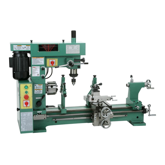
Identification Figure 1. G9729 Controls and features. A. Fine Downfeed Handle Q. Thread Chasing Dial B. Quill Downfeed Lever R. Tailstock Lock Lever C. Upper Belt Guard S. Leadscrew Hand Crank D. Head Stock Tailstock Handwheel E. Mill/Drill Motor U. Tailstock Quill Lock Head Locks V. -
Page 8: Section 1: Safety
TIRED, OR UNDER THE INFLUENCE OF RESPIRATOR WHEN OPERATING DRUGS OR ALCOHOL. Be mentally alert MACHINERY THAT PRODUCES DUST. at all times when running machinery. Wood dust is a carcinogen and can cause cancer and severe respiratory illnesses. G9729 Combination Lathe/Mill... - Page 9 Follow instructions for and animals, especially when cutting fumes lubricating and changing accessories. can be inhaled. Make sure you know what type of metal and cutting fluid you will be exposed to and how to avoid contamina- tion. G9729 Combination Lathe/Mill...
-
Page 10: Additional Safety Instructions For Lathe/Mills
No list of safety guidelines can be complete. Like all machines there is danger associ- Every shop environment is different. Always ated with the Model G9729. Accidents are consider safety first, as it applies to your frequently caused by lack of familiarity or individual working conditions. -
Page 11: Glossary Of Terms
The following is a list of common definitions, terms and phrases used throughout this manual as they relate to this lathe/mill and metalworking in general. Become familiar with these terms for assembling, adjusting or operating this machine. Your safety is VERY important to us at Grizzly! Arbor: A machine shaft that supports a cutting Fixture: A device that securely holds the tool. -
Page 12: Section 2: Circuit Requirements
If the plug Plug Type will not fit the outlet, have the proper outlet installed by a qualified electrician. The Model G9729 is supplied with a 5-15 plug, similar to Figure 2. Extension Cords •... -
Page 13: Section 3: Set Up
Unpacking The Model G9729 has a shipping weight of approximately 692 lbs. The Model G9729 was carefully packed when it Serious personal injury left our warehouse. If you discover the machine may occur if safe mov- is damaged after you have signed for delivery,... -
Page 14: Inventory
After all the parts have been removed from the two boxes, you should have the following items: Box 1: (Figure 3) A. Model G9729 Combo Lathe/Mill ....1 B. Face Plate ..........1 C. Adaptor Plate ..........1 Small Box Contents: D. -
Page 15: Hardware Recognition Chart
Hardware Recognition Chart -13- G9729 Combination Lathe/Mill... -
Page 16: Clean Up
The unpainted surfaces are coated with a waxy oil to protect them from corrosion during ship- Your Model G9729 weighs 525 lbs. Most com- ment. Remove this protective coating with a sol- mercial or garage shop floors should be sufficient vent cleaner or citrus-based degreaser such as to carry the weight. -
Page 17: Moving & Placing Base Unit
Moving & Placing Base Unit The Model G9729 requires the use of lifting equipment such as a fork lift, engine hoist or boom crane. DO NOT lift the machine by hand. Holes are provided in the edge of the lathe bed "... -
Page 18: Hand Crank
When released, the hand crank will withdraw from the leadscrew and will no lon- ger be engaged. Figure 7. Attach handles to handwheels. Key Slot Figure 6. The key is engaged with the hand crank. -16- G9729 Combination Lathe/Mill... -
Page 19: Steady And Follow Rest Removal
Steady and Follow Follow Rest Removed Rest Removal The Model G9729 Lathe/Mill comes equipped with a steady rest and follow rest. These are used to support smaller stock while turning, drilling or boring. They are installed at the factory for ship- ping purposes and should be removed at this time. -
Page 20: Test Run
Strange or unnatural noises should be personal injury. investigated and corrected before operating the machine further. If the lathe/mill is running correctly, turn the reversing switch to the OFF position, wait for the machine to come to a complete stop. -18- G9729 Combination Lathe/Mill... -
Page 21: Section 4: Lathe Operations
Operation Safety Control Panel It is vital that you become familiar with the control panel before operating the Model G9729. Damage to your eyes, lungs, and ears could Power to the two motors is controlled through a result from using this machine without series of switches mounted on the Lower and proper protective gear. -
Page 22: Lathe Chuck Removal
Tighten the other screws also but only enough so the gap between the chuck and the back plate remains even. Finally, tighten all three screws until the gap between the chuck and the back plate is closed and the screws are tight. -20- G9729 Combination Lathe/Mill... -
Page 23: Lathe Chucks With Mounting Plate
Grizzly’s current catalog for ordering information on 4-jaw chucks. To use this adaptor plate: The Model G9729 Lathe/Mill comes equipped with a 5'' 3-jaw chuck (already installed). Fasten the plate to the 4-jaw chuck using the screws provided with the chuck. -
Page 24: Chuck Jaws
While both can hold a workpiece on the inside or outside surface of the jaw, the most common uses are shown in Figure Internal Jaw Figure 13. Workholding options. Internal Jaw External Jaw Figure 12. Jaws for the 3-jaw chuck. -22- G9729 Combination Lathe/Mill... -
Page 25: Replacing Jaws
Replacing Jaws Figure 14. Arrow points to the lead of the scroll. -23- G9729 Combination Lathe/Mill... -
Page 26: Face Plate
Check your centerline, as tightening the clamps may have caused it to move. Adjust as necessary. The face plate supplied with the model G9729 Use a lower RPM when machining heavy Lathe/Mill can be easily mounted to the spindle eccentric workpieces. Take into consider- once the chuck has been removed. -
Page 27: Dead Center
Morse tapers will not interlock when dirt or oil used. The live center has bearings letting the cen- are present on the mounting surfaces. ter and the workpiece rotate together, instead of the workpiece rotating around the dead center. -25- G9729 Combination Lathe/Mill... -
Page 28: Tool Post
Tool Post The Model G9729 comes supplied with a 4-way turret tool post that is designed to accept up to four ⁄ " tool bits. Other devices and holders may be installed into the tool post and arranged as in Figure 18. -
Page 29: Tailstock Controls
4. Offset Mechanism Loosening these bolts allows the tailstock to be offset from center by turning a screw. This fea- ture will allow taper turning when a workpiece is held between centers. Figure 20. Detail of tailstock controls. -27- G9729 Combination Lathe/Mill... - Page 30 23). If the stock is thinner at the tailstock end, the tailstock needs to be moved away from the operator by at least half the amount of the taper (Figure 24). Figure 25. Tailstock offset adjustment screw. -28- G9729 Combination Lathe/Mill...
-
Page 31: Tailstock Drill Mounting
Grizzly To mount the drill chuck into the tailstock of the offers a variety of chucks and arbors. Please see lathe, slide the arbor into the tailstock quill about our current catalog for more information. -
Page 32: Carriage Controls
Therefore, rotating the dial 10 marks will move the slide 0.010", and multi- plying this amount by 0.002" equals 0.020". The workpiece diameter will be reduced by 0.020". -30- G9729 Combination Lathe/Mill... -
Page 33: Carriage Lock
Figure 29. This allows the carriage to be locked in place for precision facing operations while using the lathe or to make a set up in a milling operation more rigid. Figure 29. Carriage lock. -31- G9729 Combination Lathe/Mill... -
Page 34: Follow Rest
Loosen the knurled thumb screws for each brass finger and turn the adjusting knobs clockwise until they stop. Secure the workpiece between centers or into a 3- or 4-jaw chuck with a center mount- ed in the tailstock. -32- G9729 Combination Lathe/Mill... -
Page 35: Steady Rest
Rest on Page 32 to set the brass finger in the with the cap screw. (Refer to Figure 8 on proper position. Page 17.) Figure 32. Steady rest supporting a part to be faced. Figure 33. Loading the workpiece into the steady rest. -33- G9729 Combination Lathe/Mill... -
Page 36: Lathe Speeds
(see Figure 35). Allow the middle pulley and the shaft it is mounted on, to slide downward along the slot on the back of the belt guard. This will relax the tension of the V-belts. -34- G9729 Combination Lathe/Mill... -
Page 37: Start Up And Spindle Break-In Procedures
Failure to follow start up and spindle break- in procedures will likely cause rapid deteri- oration of spindle and other related parts. Check all oil levels and lubrication points before starting lathe. Excessive wear will result if moving parts are not lubricated! -35- G9729 Combination Lathe/Mill... -
Page 38: Feed Selection
“III” position, the feed rate is reduced by one half the feed rate of position “II”. In position “I”, roughing would most likely be done and in the “III” position, finishing would most likely be done. -36- G9729 Combination Lathe/Mill... -
Page 39: Reading The Charts
��� ��� ��� ��� ��� ��� ��� ��� ��� revolution. The available feed rates in inches per revolu- tion. The feed lever position column. The available feed rate columns. Figure 39. Feed rate selector set to “III”. -37- G9729 Combination Lathe/Mill... -
Page 40: Half Nut
NOTICE DO NOT try to engage the half nut & cross slide ring at the same time. While there is a lock-out provided against simultaneous engagement, these components could be damaged if proper procedures are ignored. -38- G9729 Combination Lathe/Mill... -
Page 41: Changing Gears
Changing Gears Changing gears on the Model G9729 is straight forward. Refer to the label found on the bottom of the lower belt guard for proper gear selection while following the example below. We will be changing the gears to those that would be used to set the machine for a 0.002"... -
Page 42: Inch Threading
120/127 combination gear. The 127 tooth side will be oriented so it is engaged with the gears in the A and D posi- tion. Field of possible threads per inch. Figure 45. Gears aligned and engaged. -40- G9729 Combination Lathe/Mill... - Page 43 The Model G9729 is capable of cutting many standard inch and metric threads. Follow the pro- cedures listed in Changing Gears in the previous section and change the gears according to the chart for the thread desired. Example: The example shown in Figures 47–50 depicts the order the gears should be installed for a 120/127, 72, and 30 tooth gear set-up.
-
Page 44: Cutting Threads
Set the feed direction lever for either right or 1 or 4 left-handed threads. Figure 51. G9729 Thread dial chart. Examine the thread charts (inch or metric), see Figures 46 & 52 , and then set the feed Examine the thread dial chart in Figure 51 rate selectors to the appropriate settings. -
Page 45: Metric Threading
Field of possible metric thread pitches. This gear will always be a 120/127 combi- nation gear and will be the intermediate to gears A and D. This gear will always have 24 teeth for metric threading. -43- G9729 Combination Lathe/Mill... -
Page 46: Section 5: Mill Operations
Head Locks Figure 55. Mill speed chart. Figure 56. Loosen stud to pivot motor and The chart in Figure 55 shows the various com- tension the belt. binations of belt positions for achieving a desired speed. -44- G9729 Combination Lathe/Mill... -
Page 47: Head Rotation
Head Rotation Fine Down Feed The head of the Model G9729 can be rotated 90° The up and down motion of the mill spindle is in both directions. controlled just like a drill press. But unlike most drill presses, the Model G9729 is supplied with... -
Page 48: Machine Vise
Step 4. The Model G9729 comes supplied with a mill- Move the vise to the starting position and ing vise that also serves as the compound for note the difference. -
Page 49: Drill Chuck Removal
DO NOT use a steel hammer! Damage to the draw bar and hammer, such as chipping, may occur. Once the arbor is loose, hold the drill chuck with one hand and unthread the arbor with the other. -47- G9729 Combination Lathe/Mill... -
Page 50: Section 6: Accessories
Natural, safe for the environment, and contains no CFC’s. H1300 H1298 G7984 H2347 Figure 61. Our most popular safety glasses. Figure 63. G7895 Citrus Degreaser. -48- G9729 Combination Lathe/Mill... - Page 51 0.001 resolution. these dust, chip, and oil proof live centers feature 60° included angle and preloaded taper bearings. Choose from MT #1 through MT #4. Figure 67. Dial Indicator. Figure 65. Live center. -49- G9729 Combination Lathe/Mill...
-
Page 52: Section 7: Maintenance
Gun Treatment, SLIPIT , or ® ® Monthly Check: T-9 (see ACCESSORIES section on Boeshield ® • V-belt tension, damage, or wear. Page 48 for more details). • Clean/vacuum dust buildup from inside cabi- net and off motor. -50- G9729 Combination Lathe/Mill... -
Page 53: Lubrication
Lubrication Your Model G9729 will function best when it is clean and well lubricated. Take the time to wipe down and oil the machine before each use. We recommend using ISO 68 or SAE 20W non- detergent oil unless otherwise specified. Ball fit- tings will require the use of an oil gun. - Page 54 To remove the oil in the gear box, remove the change gear directly under the spindle, remove the cap screw indicated in Figure 71, and place a can under the drain hole to collect the waste oil. Figure 71. Drain oil cap screw. -52- G9729 Combination Lathe/Mill...
-
Page 55: Section 8: Service
This section is provided for your convenience— it is not a substitute for the Grizzly Service Department. If any adjustments arise that are not described in this manual, then feel free to call the Grizzly Service Department at (570) 546-9663. - Page 56 It is important that the set screws are tight- ened evenly. A slight drag should be detected while turning the hand crank on the apron. Figure 76. Apron gib set screws. -54- G9729 Combination Lathe/Mill...
-
Page 57: Troubleshooting
1. Adjust for appropriate RPM and feed rate. 2. Dull cutter or poor cutter selection. 2. Sharpen cutter or select a better cutter for the intended operation. 3. Wrong rotation of cutter. 3. Check for proper cutting rotation for cutting tool. -55- G9729 Combination Lathe/Mill... -
Page 58: Electrical Diagram
��� � E-Stop Switch ��� �� � ��� � Power Switch Mill Switch Lathe Switch �� �� �� �� �� �� �� �� �� �� �� �� Lathe Motor Mill Motor Figure 77. G9729 wiring diagram. -56- G9729 Combination Lathe/Mill... -
Page 59: Electrical Components
Electrical Components Micro Switch Run Capacitor Start Capacitor Power Light Power Button E-Stop Button Lathe Reversing Switch AC Contactor Wiring Block -57- G9729 Combination Lathe/Mill... -
Page 60: Parts
PARTS G9729 Lathe Bed -58- G9729 Combination Lathe/Mill... -
Page 61: G9729 Parts Breakdown 0-199 Series
G9729 Parts Breakdown 0-199 Series PART # DESCRIPTION PART # DESCRIPTION P9729001 3-JAW CHUCK P9729120 MOTOR MOUNT P9729002 DEAD CENTER P9729121 T-BUSHING P9729006 TOOL POST WRENCH P9729122 BRACKET P9729007 DOUBLE END WRENCH P9729123 T-NUT PAW03M HEX WRENCH 3MM P9729124 GEAR 120/127... -
Page 62: G9729 Lower Head Assembly
G9729 Lower Head Assembly -60- G9729 Combination Lathe/Mill... -
Page 63: G9729 Parts Breakdown 200 Series
G9729 Parts Breakdown 200 Series REF PART # DESCRIPTION REF PART # DESCRIPTION PB31M HEX BOLT M10-1.5 X 40 PK90M KEY 10 X 10 X 25 PW04M FLAT WASHER 10MM PSB33M CAP SCREW M5-.8 X 12 P9729203 TAPER PIN 10 X 40... -
Page 64: G9729 Belt Guard
G9729 Belt Guard -62- G9729 Combination Lathe/Mill... -
Page 65: G9729 Parts Breakdown 300 Series
G9729 Parts Breakdown 300 Series PART # DESCRIPTION PART # DESCRIPTION P9729301 STRAIN RELIEF 1/2" SNAP IN P9729319 ELECTRICAL PLATE PS56M PHLP HD SCR M4-.7 X 16 PS38M PHLP HD SCR M4-.7 X 10 PS07M PHLP HD SCR M4-.7 X 8... -
Page 66: G9729 Headstock Assembly
G9729 Headstock Assembly ��� ��� ��� ��� ��� ��� ��� ��� ��� ��� ��� ��� ��� ��� ��� � � ��� � � ��� � ��� ��� ��� ��� ��� ��� ��� ��� ��� ��� ��� ��� ��� ��� ���... -
Page 67: G9729 Parts Breakdown 500 & 600 Series
G9729 Parts Breakdown 500 & 600 Series PART # DESCRIPTION PART # DESCRIPTION PVM33 V-BELT M-33 3L330 PW03M FLAT WASHER 6MM PSB47M CAP SCREW M10-1.5 X 40 PS14M PHLP HD SCR M6-1 X 12 P9729503 MILL-DRILL HEAD P9729546 MOTOR MOUNT... -
Page 68: G9729 Crossslide Assembly
G9729 Crossslide Assembly -66- G9729 Combination Lathe/Mill... -
Page 69: G9729 Parts Breakdown 700 Series
G9729 Parts Breakdown 700 Series PART # DESCRIPTION PART # DESCRIPTION PSB15M CAP SCREW M5-.8 X 20 PRP49M ROLL PIN 5 X 25 P9729702 TAPERED PIN 5 X 25 P9729745 P9729703 END PLATE B P9729746 PIVOT ARM P9729704 TABLE P9729747... -
Page 70: G9729 Apron Assembly
G9729 Apron Assembly ��� ��� ��� ��� ��� ��� ��� ��� ��� ��� ��� ��� ��� ��� ��� ��� ��� ��� ��� ��� ��� ��� ��� ��� ��� ��� ��� ��� ��� ��� ��� ��� ��� ��� ��� ��� ���... -
Page 71: G9729 Parts Breakdown T Series
G9729 Parts Breakdown T Series PART # DESCRIPTION PART # DESCRIPTION T201 T706 P9729T706 BASE P9729T201 THREAD DIAL SEAT T202 P9729T202 SHAFT T707 P9729T707 RIVET T203 P9729T203 INDICATOR PLATE T708 P9729T708 SCALE T204 P9729T204 PHLP HD SCREW M4-.7 X 12... -
Page 72: G9729 Rests Assemblies
G9729 Rests Assemblies ���� ���� ���� ���� ���� ���� ���� ���� ���� ���� ���� ���� ���� ���� ���� ���� ���� ���� ���� ���� ���� ���� ���� ���� ���� ���� ���� ���� ���� ���� ������ ������ -70- G9729 Combination Lathe/Mill... -
Page 73: G9729 Compound Assembly
G9729 Compound Assembly -71- G9729 Combination Lathe/Mill... -
Page 74: G9729 Tailstock Assembly
G9729 Tailstock Assembly ��� ��� ��� ��� ��� ��� ��� ��� ��� ��� ��� ��� ��� ��� ��� ��� ��� ��� ��� ��� ��� ��� ��� ��� ��� ��� ��� ��� ��� ��� ��� ��� ��� ��� ��� � ���... -
Page 75: G9729 Parts Breakdown 900 Series
G9729 Parts Breakdown 900 Series PART # DESCRIPTION PART # DESCRIPTION P9729901 TAILSTOCK P9729921 STUD M10-1.5 X 40 P9729902 T-KEY P9729922 SPACER P9729903 TAILSTOCK NUT P9729923 HANDLE HUB P9729904 TAILSTOCK BARREL P9729924 HANDLE PSS52M SET SCREW M4-.7 X 8 P9729925 HANDLE KNOB M10-1.5... -
Page 76: Warranty And Returns
WARRANTY AND RETURNS Grizzly Industrial, Inc. warrants every product it sells for a period of 1 year to the original purchaser from the date of purchase. This warranty does not apply to defects due directly or indirectly to misuse, abuse, negligence, accidents, repairs or alterations or lack of maintenance. -
Page 77: Warranty Card
Would you recommend Grizzly Industrial to a friend? _____ Yes _____No Would you allow us to use your name as a reference for Grizzly customers in your area? Note: We never use names more than 3 times. _____ Yes _____No 10. - Page 78 FOLD ALONG DOTTED LINE Place Stamp Here GRIZZLY INDUSTRIAL, INC. P.O. BOX 2069 BELLINGHAM, WA 98227-2069 FOLD ALONG DOTTED LINE Send a Grizzly Catalog to a friend: Name_______________________________ Street_______________________________ City______________State______Zip______ TAPE ALONG EDGES--PLEASE DO NOT STAPLE...
- Page 80 Buy Direct and Save with Grizzly – Trusted, Proven and a Great Value! ® Visit Our Website Today And Discover Why Grizzly Is The Industry Leader! ® • SECURE ORDERING • ORDERS SHIPPED WITHIN 24 HOURS • E-MAIL RESPONSE WITHIN ONE HOUR...
Need help?
Do you have a question about the G9729 and is the answer not in the manual?
Questions and answers