Basler DGC-2020ES Instruction Manual
Digital genset controller
Hide thumbs
Also See for DGC-2020ES:
- Quick start instruction manual (390 pages) ,
- Instruction manual (228 pages) ,
- Configuration instruction manual (156 pages)
Table of Contents

Subscribe to Our Youtube Channel
Related Manuals for Basler DGC-2020ES


Summary of Contents for Basler DGC-2020ES
- Page 1 DGC-2020ES Digital Genset Controller Accessories Instruction Manual Publication 12570 Route 143 • Highland, Illinois 62249-1074 USA Tel +1 618.654.2341 • Fax +1 618.654.2351 9469200997, Rev C www.basler.com • info@basler.com July 2021...
- Page 2 Proposition 65 warning, we are notifying you that one or more of the Proposition 65 listed chemicals may be present in products we sell to you. For more information about the specific chemicals found in this product, please visit https://www.basler.com/Prop65.
-
Page 3: Conventions Used In This Manual
9469200997 Preface This instruction manual provides information about the accessories for the DGC-2020ES Digital Genset Controller. To accomplish this, the following information is provided: CEM-2020 (Contact Expansion Module) • Conventions Used in this Manual Important safety and procedural information is emphasized and presented in this manual through Warning, Caution, and Note boxes. - Page 4 The availability and design of all features and options are subject to modification without notice. Over time, improvements and revisions may be made to this publication. Before performing any of the following procedures, contact Basler Electric for the latest revision of this manual.
-
Page 5: Revision History
9469200997 Revision History A historical summary of the changes made to this instruction manual is provided below. Revisions are listed in reverse chronological order. Visit www.basler.com to download the latest hardware, firmware, and BESTCOMSPlus revision ® histories. Instruction Manual Revision History... - Page 6 9469200997 Revision History DGC-2020ES...
- Page 7 9469200997 Contents CEM-2020 ..............................1-1 Troubleshooting ............................2-1 DGC-2020ES Contents...
- Page 8 9469200997 Contents DGC-2020ES...
-
Page 9: General Information
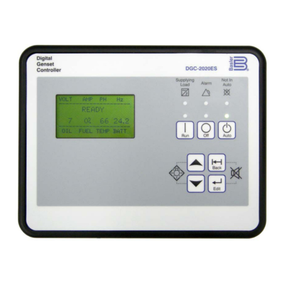
1 • CEM-2020 General Information The optional CEM-2020 is a remote auxiliary device that provides additional DGC-2020ES contact inputs and outputs. Two types of modules are available. A low current module (CEM-2020) provides 24 contact outputs and high current module (CEM-2020H) provides 18 contact outputs. - Page 10 Tested in close proximity to an unshielded, unsuppressed Altronic DISN 800 ignition system. HALT (Highly Accelerated Lift Testing) HALT is used by Basler Electric to prove that our products will provide the user with many years of reliable service. HALT subjects the device to extremes in temperature, shock, and vibration to simulate years of operation, but in a much shorter period span.
-
Page 11: Functional Description
The CEM-2020 provides 24 programmable contact outputs with the same functionality as the contact outputs on the DGC-2020ES. Outputs 5 through 16 can carry 1 A. Outputs 17 through 28 can carry 4 A. The label text of each contact output is customizable. -
Page 12: Bestcomsplus ® Software
Inspect for damage, and if there is evidence of such, immediately file a claim with the carrier and notify the Basler Electric regional sales office or your sales representative. - Page 13 9469200997 Figure 1-1. CEM-2020 Overall Dimensions See Figure 1-2 for CEM-2020H overall dimensions. All dimensions are shown in inches with millimeters in brackets. DGC-2020ES CEM-2020...
- Page 14 5 inch-pounds (0.56 N•m). Operating Power The Contact Expansion Module operating power input accepts either 12 Vdc or 24 Vdc and tolerates voltage over the range of 6 to 32 Vdc. Operating power must be of the correct polarity. Although reverse CEM-2020 DGC-2020ES...
- Page 15 Contact Inputs and Contact Outputs The CEM-2020 (Figure 1-3) has 10 contact inputs and 24 contact outputs. The CEM-2020H (Figure 1-4) has 10 contact inputs and 18 contact outputs. Figure 1-3. CEM-2020 Contact Input and Contact Output Terminals DGC-2020ES CEM-2020...
- Page 16 These terminals provide communication using the SAE J1939 protocol and provide high-speed communication between the Contact Expansion Module and the DGC-2020ES. Connections between the CEM-2020 and DGC-2020ES should be made with twisted-pair, shielded cable. CAN interface terminals are listed in Table 1-2. Refer to Figure 1-5 and Figure 1-6.
- Page 17 Figure 1-5. CAN Interface with CEM-2020 providing One End of the Bus CEM-2020 (Optional) Stub CAN-H DGC-2020ES Engine CAN-L P0067-85 120 ohm 120 ohm Other Termination Termination Devices Figure 1-6. CAN Interface with DGC-2020ES providing One End of the Bus DGC-2020ES CEM-2020...
- Page 18 The Remote Contact Outputs screen is found in the BESTCOMSPlus Settings Explorer under the Programmable Inputs category. If using the front panel, navigate to Settings > Programmable Outputs > Configurable Outputs. The BESTCOMSPlus Contact Outputs screen is illustrated in Figure 1-8. CEM-2020 DGC-2020ES...
-
Page 19: Firmware Updates
Repair Contact Expansion Modules are manufactured using state-of-the-art surface-mount technology. As such, Basler Electric recommends that no repair procedures be attempted by anyone other than Basler Electric personnel. Before returning the CEM-2020 for repair, contact Basler Electric Technical Services Department at 618- 654-2341 for a return authorization number. - Page 20 1-12 9469200997 CEM-2020 DGC-2020ES...
-
Page 21: Troubleshooting
9469200997 2 • Troubleshooting If you do not get the results that you expect from the DGC-2020ES, first check the programmable settings for the appropriate function. Use the following troubleshooting procedures when difficulties are encountered in the operation of your genset control system. - Page 22 Use a voltmeter connected between the BATT– terminal (17) and the SENDER COM terminal (2) on the DGC-2020ES to verify that there is no voltage difference at any time. Any voltage differences may manifest themselves as erratic sender readings. Wiring should be corrected so that no differences exist.
-
Page 23: Ground Faults Detected In Ungrounded System Applications
Step 3: If ground faults are detected on a DGC-2020ES in an ungrounded system application, it is recommended that potential transformers be employed on the voltage sensing inputs to provide full isolation between the DGC-2020ES and monitored voltage phases. - Page 24 9469200997 Step 8: Verify the wiring to the breaker from the DGC-2020ES. If it seems OK, you can do a manual close and open by modifying the programmable logic. Map some unused outputs to the OPEN and CLOSE outputs from the Gen Breaker Block in the programmable logic. Map a virtual switch to the logic output that would normally be the breaker open output.
-
Page 25: Dgc-2020Es Front Panel Debug Screen
CONDITION DETECTION screen to achieve correct detection. Step 5: Verify the wiring to the breaker from the DGC-2020ES. If it seems OK, you can do a manual close and open by modifying the programmable logic. Map some unused outputs to the OPEN and CLOSE outputs from the Gen Breaker Block in the programmable logic. - Page 26 9469200997 Troubleshooting DGC-2020ES...
- Page 28 Highland IL 62249-1074 USA Suzhou Industrial Park 15-06 Peninsula Plaza Tel: +1 618.654.2341 215122 Suzhou Singapore 179098 Fax: +1 618.654.2351 P.R. CHINA Tel: +65 68.44.6445 email: info@basler.com Tel: +86 512.8227.2888 Fax: +65 68.44.8902 Fax: +86 512.8227.2887 email: singaporeinfo@basler.com email: chinainfo@basler.com...
Need help?
Do you have a question about the DGC-2020ES and is the answer not in the manual?
Questions and answers