Table of Contents
Advertisement
Quick Links
16 SPEED GEARHEAD LATHE
MODEL SB1053 14" X 40"
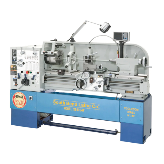
MODEL SB1054F 16" X 40" w/DRO
MODEL SB1055F 16" X 60" w/DRO
OWNER'S MANUAL
Q
Hundreds of Thousands of Lathes Sold With a Tradition of
uality Since 1906!
© June, 2011 by South Bend Lathe Co.
For Machines Mfg. Since 3/11
Downloaded from
www.Manualslib.com
manuals search engine
Advertisement
Table of Contents

Subscribe to Our Youtube Channel
Related Manuals for South bend SB1053


Summary of Contents for South bend SB1053
- Page 1 MODEL SB1055F 16" X 60" w/DRO OWNER'S MANUAL Hundreds of Thousands of Lathes Sold With a Tradition of uality Since 1906! © June, 2011 by South Bend Lathe Co. For Machines Mfg. Since 3/11 Downloaded from www.Manualslib.com manuals search engine...
- Page 2 What did you like about it? Is there anything you would change to make it better? Did it meet your expectations for clarity, professionalism, and ease-of-use? South Bend Lathe, Inc. Technical Documentation Manager P.O. Box 2027 Bellingham, WA 98227 Email: manuals@southbendlathe.com...
-
Page 3: Table Of Contents
..........8 Tailstock Controls Scroll Chuck Clamping ........37 ............8 Foot Brake 4-Jaw Chuck ............37 SB1053 Machine Specifications ......9 .......... 37 Mounting Workpiece SB1054F Machine Specifications ......9 Faceplate ............38 SB1055F Machine Specifications ......9 Tailstock ............. 39 SAFETY ..............13... - Page 4 ....... 51 Brake & Switch ..........81 Compound Rest Handwheel Spindle Speed ............. 51 Leadscrew Shear Pin Replacement ....82 ........ 51 Gap Insert Removal & Installation ....85 Determining Spindle Speed ........52 ............. 85 Setting Spindle Speed Gap Removal ........
-
Page 5: Introduction
As the operator of a South Bend Lathe, you now join the ranks of some very famous and important customers, such as Henry Ford, who used the machines he purchased to help him change the world. -
Page 6: General Identification
I N T R O D U C T I O N For Machines Mfg. Since 3/11 16-Speed Gearhead Lathe General Identification Figure 1. General identification (Model SB1054F shown). A. Headstock K. Tailstock B. D1-6 Camlock MT#6 Spindle Longitudinal Leadscrew Chuck Guard w/Safety Switch M. -
Page 7: Controls & Components
I N T R O D U C T I O N For Machines Mfg. Since 3/11 16-Speed Gearhead Lathe Controls & Two-Speed Motor Switch Components Refer to Figures 2–9 and the following descriptions to become familiar with the features and basic controls of this lathe. -
Page 8: Feed Controls
I N T R O D U C T I O N For Machines Mfg. Since 3/11 16-Speed Gearhead Lathe Coolant Switch: Starts and stops the coolant Feed Controls pump. Fluid flow is controlled by the valve on the coolant nozzle. Feed Range Lever Power Light: Illuminates when power is enabled to all lathe electrical controls. -
Page 9: Carriage Controls
I N T R O D U C T I O N For Machines Mfg. Since 3/11 16-Speed Gearhead Lathe Thread Dial: Indicates when to engage the Carriage Controls half nut during inch threading operations. G. Spindle ON/OFF Lever: Starts, stops and reverses direction of spindle rotation. -
Page 10: Tailstock Controls
I N T R O D U C T I O N For Machines Mfg. Since 3/11 16-Speed Gearhead Lathe Tailstock Controls Foot Brake This lathe is equipped with a foot brake (see Figure 10) to quickly stop the spindle instead of allowing it to coast to a stop on its own. -
Page 11: Sb1053 Machine Specifications
I N T R O D U C T I O N For Machines Mfg. Since 3/11 16-Speed Gearhead Lathe Product Specifications P.O. Box 2027, Bellingham, WA 98227 U.S.A. © South Bend Lathe Co. www.southbendlathe.com MODEL SB1053, SB1054F, SB1055F 16 SPEED GEARHEAD LATHES Model Number... - Page 12 I N T R O D U C T I O N For Machines Mfg. Since 3/11 16-Speed Gearhead Lathe Model Number SB1053 SB1054F SB1055F Main Motor Type TEFC Induction TEFC Induction TEFC Induction Horsepower 7.5 HP 7.5 HP 7.5 HP...
- Page 13 I N T R O D U C T I O N For Machines Mfg. Since 3/11 16-Speed Gearhead Lathe Model Number SB1053 SB1054F SB1055F Headstock Information Spindle Bore 2.06 in. 2-1/16 in. 2-1/16 in. Spindle Taper MT#6 MT#6 MT#6...
- Page 14 I N T R O D U C T I O N For Machines Mfg. Since 3/11 16-Speed Gearhead Lathe Model Number SB1053 SB1054F SB1055F Construction Headstock Cast Iron Cast Iron Cast Iron Headstock Gears Flame-Hardened Steel Flame-Hardened Steel Flame-Hardened Steel...
-
Page 15: Safety
S A F E T Y For Machines Mfg. Since 3/11 16-Speed Gearhead Lathe SAFETY Understanding Risks of Machinery Operating all machinery and machining equipment can be dangerous or relatively safe depending on how it is installed and maintained, and the operator's experience, common sense, risk awareness, working conditions, and use of personal protective equipment (safety glasses, respirators, etc.). - Page 16 S A F E T Y For Machines Mfg. Since 3/11 16-Speed Gearhead Lathe Entanglement: Loose clothing, gloves, neckties, Chuck Keys or Adjusting Tools: Tools used to jewelry or long hair may get caught in adjust spindles, chucks, or any moving/ moving parts, causing entanglement, rotating parts will become dangerous amputation, crushing, or strangulation.
-
Page 17: Additional Metal Lathe Safety
S A F E T Y For Machines Mfg. Since 3/11 16-Speed Gearhead Lathe Additional Metal Lathe Safety Clearing Chips. Metal chips can easily cut bare Speed Rates. Operating the lathe at the wrong skin—even through a piece of cloth. Avoid speed can cause nearby parts to break or the clearing chips by hand or with a rag. -
Page 18: Chuck Safety
S A F E T Y For Machines Mfg. Since 3/11 16-Speed Gearhead Lathe Chuck Safety Entanglement. Entanglement with a rotating Chuck Capacity. Avoid exceeding the capacity chuck can lead to death, amputation, broken of the chuck by clamping an oversized bones, or other serious injury. -
Page 19: Preparation
P R E P A R A T I O N For Machines Mfg. Since 3/11 16-Speed Gearhead Lathe PREPARATION Preparation Overview Things You'll Need The purpose of the preparation section is to help To complete the preparation process, you will you prepare your machine for operation. -
Page 20: Power Supply Requirements
SB1053 Full-Load Rating ....20.3 Amps SB1054F Full-Load Rating .... 10.15 Amps SB1055F Full-Load Rating .... 10.23 Amps For your own safety and protection of property, consult a qualified electrician if you are unsure... -
Page 21: Grounding Requirements
220V Operation The power cord and plug specified under Circuit Requirements section for the Model SB1053 on LOCKING DISCONNECT SWITCH the previous page has an equipment-grounding wire and a grounding prong. The plug must only... -
Page 22: Unpacking
Hex Wrench 10mm ........1 U. Cast Iron Feet ..........8 Installed & Not Shown SB1309 9" 3-Jaw Chuck (SB1053) ....1 SB1310 10" 3-Jaw Chuck (SB1054F-55F) ..1 Note: Some inventory components or additional documentation may be shipped inside of the lathe electrical cabinet. -
Page 23: Cleaning & Protecting
P R E P A R A T I O N For Machines Mfg. Since 3/11 16-Speed Gearhead Lathe Cleaning & Protecting The unpainted surfaces are coated at the factory Many cleaning solvents are with a heavy-duty rust preventative that toxic if inhaled. -
Page 24: Location
P R E P A R A T I O N For Machines Mfg. Since 3/11 16-Speed Gearhead Lathe Weight Load Location Refer to the Machine Specifications for the weight of your machine. Make sure that the Physical Environment surface upon which the machine is placed will The physical environment where your machine Physical Environment bear the weight of the machine, additional... -
Page 25: Lifting & Moving
P R E P A R A T I O N For Machines Mfg. Since 3/11 16-Speed Gearhead Lathe To further balance the load, loosen the Lifting & Moving carriage lock bolt (see Figure 17), disengage the half nut lever, disengage the feed control lever, then use the carriage handwheel to move the carriage next to the tailstock. -
Page 26: Leveling & Mounting
P R E P A R A T I O N For Machines Mfg. Since 3/11 16-Speed Gearhead Lathe Attach the lifting straps to the forklift Leveling & Mounting forks or a hook and chain, as shown in Figures 19–20. You must level your machine and either use the included foot pads and leveling hardware or bolt and shim your lathe to the floor. -
Page 27: Bolting To Concrete Floors
P R E P A R A T I O N For Machines Mfg. Since 3/11 16-Speed Gearhead Lathe To level the machine, use a precision level to Assembly make sure the bedways are level from side-to- side and from front-to-back. With the exception of the handwheel handles, the lathe is shipped fully assembled. -
Page 28: Adding Coolant
Disconnect Switch Power Source Machine machine is ready to be connected to the power supply. Model SB1053 Connect a power cord that meets the Circuit Requirements on Page 18, as instructed later in this subsection. Attach a locking NEMA L15- Conduit... - Page 29 P R E P A R A T I O N For Machines Mfg. Since 3/11 16-Speed Gearhead Lathe Note: For the Model SB1053, thread the power cord through an approved and properly sized strain relief as it enters the Electrocution could occur if you attempt this electrical cabinet.
-
Page 30: Test Run
P R E P A R A T I O N For Machines Mfg. Since 3/11 16-Speed Gearhead Lathe DISCONNECT LATHE FROM POWER! Test Run Make sure that the chuck and jaws, if After all preparation steps have been completed, installed, are secure (refer to Chuck the machine and its safety features must be Installation on Page 35), then lower the... - Page 31 P R E P A R A T I O N For Machines Mfg. Since 3/11 16-Speed Gearhead Lathe Set the spindle speed to 40 RPM. You may have to manually rock the chuck back-and- Lock Bolt Half nut Lever forth to make the gears mesh.
- Page 32 P R E P A R A T I O N For Machines Mfg. Since 3/11 16-Speed Gearhead Lathe 12. Connect the lathe to the power source, then — When operating correctly, the machine turn the master power switch to the ON runs smoothly with little or no vibration position (see Figure 34).
- Page 33 P R E P A R A T I O N For Machines Mfg. Since 3/11 16-Speed Gearhead Lathe 17. Move the spindle ON/OFF lever to the OFF 22. Lift the chuck guard up—this will activate (middle) position, reset the STOP button by the chuck guard safety switch.
-
Page 34: Spindle Break-In
P R E P A R A T I O N For Machines Mfg. Since 3/11 16-Speed Gearhead Lathe Set the spindle speed to 40 RPM and let the Spindle Break-In lathe run for a final 15 minutes to allow it to cool down, then turn the lathe OFF. -
Page 35: Operation
O P E R A T I O N For Machines Mfg. Since 3/11 16-Speed Gearhead Lathe OPERATION To complete a typical operation, the operator Operation Overview does the following: The purpose of this overview is to provide Puts on safety glasses, rolls up sleeves, the novice machine operator with a basic removes jewelry, and secures any clothing, understanding of how the machine is used during... -
Page 36: Chuck & Faceplate Mounting
O P E R A T I O N For Machines Mfg. Since 3/11 16-Speed Gearhead Lathe Chuck & Faceplate Installation & Removal Mounting Devices This lathe is equipped with a D1-type spindle Because chucks are heavy and often awkward to nose. -
Page 37: Chuck Installation
O P E R A T I O N For Machines Mfg. Since 3/11 16-Speed Gearhead Lathe Incrementally tighten the camlocks in a Chuck Installation criss-cross or star pattern to ensure that the chuck seats evenly against the spindle. To ensure accurate work, it is extremely important to make sure the spindle nose and When the chuck is fully seated and all the chuck mating surfaces/tapers are clean. -
Page 38: Registration Marks
O P E R A T I O N For Machines Mfg. Since 3/11 16-Speed Gearhead Lathe Verify that the chuck fits the spindle Chuck Removal properly by checking for any gaps between the mating surfaces. To remove the chuck: DISCONNECT LATHE FROM POWER! —... -
Page 39: Scroll Chuck Clamping
O P E R A T I O N For Machines Mfg. Since 3/11 16-Speed Gearhead Lathe Scroll Chuck Clamping 4-Jaw Chuck This scroll-type chuck has an internal scroll-gear Refer to the Chuck Installation (see Page 35) that moves all jaws in unison when adjusted with and Chuck Removal (see Page 36) instructions the chuck key. -
Page 40: Faceplate
O P E R A T I O N For Machines Mfg. Since 3/11 16-Speed Gearhead Lathe Tighten each jaw in small increments. After Faceplate you have adjusted the first jaw, continue tightening in an opposing sequence, as Refer to the Chuck Installation (Page 35) and shown in Figure 43. -
Page 41: Tailstock
O P E R A T I O N For Machines Mfg. Since 3/11 16-Speed Gearhead Lathe To mount a non-concentric workpiece to the Tailstock Lock Lever faceplate: DISCONNECT LATHE FROM POWER! Protect the bedway with a piece of plywood. With the help from another person or a holding device to support the workpiece, position it onto the faceplate and clamp it in... -
Page 42: Installing Tooling
O P E R A T I O N For Machines Mfg. Since 3/11 16-Speed Gearhead Lathe However, other tooling without tangs, such as Installing Tooling the four remaining tools shown in Figure 47, This tailstock uses a quill with an MT#4 taper can still be used if the potential load will not that has a lock slot in the back of the bore that override the strength of the tapered fit. -
Page 43: Removing Tooling
O P E R A T I O N For Machines Mfg. Since 3/11 16-Speed Gearhead Lathe Removing Tooling Offsetting Tailstock Use a shop rag to hold the tool. The tailstock can be offset from the spindle centerline for turning tapers. Move the tailstock Rotate the tailstock handwheel top casting toward the front of the lathe to counterclockwise until the tool is forced out... -
Page 44: Aligning Tailstock To Spindle Centerline
O P E R A T I O N For Machines Mfg. Since 3/11 16-Speed Gearhead Lathe Rotate the adjustment cap screws in opposite Use the other piece of round stock to make directions for the desired offset (see the a dead center, and turn it to a 60°... -
Page 45: Centers
O P E R A T I O N For Machines Mfg. Since 3/11 16-Speed Gearhead Lathe Note: If necessary in the following step, refer Centers to Offsetting Tailstock on Page 41 for detailed instructions. Figure 56 shows the MT#4 dead centers included with the lathe. -
Page 46: Live Centers
O P E R A T I O N For Machines Mfg. Since 3/11 16-Speed Gearhead Lathe Live Centers Removing Center from Spindle A live center has bearings that allow the center To remove the sleeve and center from the tip and the workpiece to rotate together;... -
Page 47: Removing Center From Tailstock
O P E R A T I O N For Machines Mfg. Since 3/11 16-Speed Gearhead Lathe Use the tailstock handwheel to feed the quill Mounting Workpiece Between out from the casting approximately 1". Centers Note: Do not extend the quill more than 2" or DISCONNECT LATHE FROM POWER! stability and accuracy will be reduced. -
Page 48: Steady Rest
O P E R A T I O N For Machines Mfg. Since 3/11 16-Speed Gearhead Lathe Loosen the clamp knob that secures the two Steady Rest halves of the rest and open the top portion, as shown in Figure 62. The steady rest supports long shafts and can be mounted anywhere along the length of the bedway. -
Page 49: Follow Rest
O P E R A T I O N For Machines Mfg. Since 3/11 16-Speed Gearhead Lathe Follow Rest Carriage & Compound The follow rest mounts to the saddle with two Rest Locks cap screws (see Figure 63). It is used on long, slender parts to prevent workpiece deflection The carriage and compound rest have locks that from the pressure of the cutting tool during... -
Page 50: Compound Rest
O P E R A T I O N For Machines Mfg. Since 3/11 16-Speed Gearhead Lathe Compound Rest Four-Way Tool Post The compound rest handwheel has an indirect- The four-way tool post is mounted on top of the read graduated scale. This means that the compound rest and allows a maximum of four distance shown on the scale represents the actual tools to be loaded simultaneously. -
Page 51: Aligning Cutting Tool With Spindle Centerline
O P E R A T I O N For Machines Mfg. Since 3/11 16-Speed Gearhead Lathe Aligning Cutting Tool with Spindle Tools Needed Tool Post T-Wrench ..........1 Centerline Steel Shims ..........As Needed For most operations, the cutting tool tip should Cutting Tool ............ -
Page 52: Adjustable Feed Stop
O P E R A T I O N For Machines Mfg. Since 3/11 16-Speed Gearhead Lathe Adjustable Feed Stop Micrometer Stop This machine features an adjustable stop system The micrometer stop used to limit carriage travel that can be used to stop the carriage at a pre-set for production runs or make final adjustments location when it is being driven by the feed rod. -
Page 53: Manual Feed
O P E R A T I O N For Machines Mfg. Since 3/11 16-Speed Gearhead Lathe Manual Feed Spindle Speed The handwheels shown in Figure 71, and Using the correct spindle speed is important described below, allow the operator to manually for safe and satisfactory results, as well as move the cutting tool. -
Page 54: Setting Spindle Speed
O P E R A T I O N For Machines Mfg. Since 3/11 16-Speed Gearhead Lathe Setting Spindle Speed Configuration Examples Selecting one of the 16 spindle speeds available is Use the following examples to better understand a combination of configuring the two-speed motor how to read the spindle speed chart and switch, the spindle range lever, and the spindle configure the controls for the correct speed. -
Page 55: Power Feed
O P E R A T I O N For Machines Mfg. Since 3/11 16-Speed Gearhead Lathe Move the spindle speed lever so that the Power Feed indicator points to the letter "A". This will select the spindle speed of 40 RPM in the top Both the carriage and cross slide have power feed row of the chart. -
Page 56: Power Feed Controls
O P E R A T I O N For Machines Mfg. Since 3/11 16-Speed Gearhead Lathe Quick-Change Gearbox Feed Levers: Configure Power Feed Controls the quick-change gearbox gears for the feed rate Use Figures 77–80 and the following selected (see Figure 79). descriptions to become familiar with the locations and functions of the controls that you will use to set up the correct power feed for your operation. -
Page 57: Setting Feed Rate
O P E R A T I O N For Machines Mfg. Since 3/11 16-Speed Gearhead Lathe Feed Direction Knob: Changes power feed Using the controls on the lathe, follow along with direction (see Figure 80). the example below to better understand how to set the lathe for the desired power feed rate. -
Page 58: End Gears
O P E R A T I O N For Machines Mfg. Since 3/11 16-Speed Gearhead Lathe The configuration string of characters to End Gears the right of the selected feed rate (LCS8W) displays the positions to set the feed controls The end gears on the side of the headstock can be for a feed rate of 0.18mm/rev. -
Page 59: Alternate Configuration
O P E R A T I O N For Machines Mfg. Since 3/11 16-Speed Gearhead Lathe Loosen the pivot arm hex nut shown in Alternate Configuration Figure 85, then swing the pivot arm to the Use the alternate end gear configuration when left so that 44T/56T gears are away from the cutting modular or diametral threads, as 57T gear. -
Page 60: Threading Controls
O P E R A T I O N For Machines Mfg. Since 3/11 16-Speed Gearhead Lathe The configuration string of characters to the Threading Controls right of the selected thread pitch (LCR3Y) displays the positions to set the threading The following subsections describe how to use controls for a metric thread width of 2.5mm. -
Page 61: Apron Controls
O P E R A T I O N For Machines Mfg. Since 3/11 16-Speed Gearhead Lathe Apron Controls Thread Dial The half nut lever engages the apron with The numbers on the thread dial are used with the leadscrew which moves the carriage and the thread dial chart to show when to engage the cutting tool along the length of the workpiece for half nut during inch threading. -
Page 62: Thread Dial Chart
O P E R A T I O N For Machines Mfg. Since 3/11 16-Speed Gearhead Lathe Thread Dial Chart Even TPI Not Divisible By 4 For threading a TPI that is even but not divisible Find the TPI (threads per inch) that you want by 4, use any of the non-numbered lines on the to cut in the left column of the thread dial chart thread dial (see Figure 91). -
Page 63: Chip Drawer
O P E R A T I O N For Machines Mfg. Since 3/11 16-Speed Gearhead Lathe ⁄ ⁄ Fractional TPI Chip Drawer For TPI that have a ⁄ ⁄ fraction, use position The chip drawer shown in Figure 96 catches 1 on the thread dial (see Figure 94). -
Page 64: Coolant System
O P E R A T I O N For Machines Mfg. Since 3/11 16-Speed Gearhead Lathe Coolant System When the coolant pump switch is turned ON, the BIOLOGICAL & POISON fluid is delivered through the nozzle attached to HAZARD! the carriage. -
Page 65: Accessories
1.378" SB1268—Collect Attachment 60° This collet attachment takes advantage of the South Bend factory-made collet port in the lathe gear cover. This accessory installs easily on these South Bend Lathes without having Figure 101. Model SB1239 High Performance Live to modify the gear cover. The Model SB1268 is Center. - Page 66 60° Figure 104. Antique-finished South Bend shop clocks. SB1251—Heavy-Duty Oak Tool Chest Proudly made in the South Bend tradition, this Figure 102. SB1247 MT4 Bull Nose Center. heavy-duty oak tool chest will safeguard your finest tools for may years of dependable service.
-
Page 67: Maintenance
M A I N T E N A N C E For Machines Mfg. Since 3/11 16-Speed Gearhead Lathe MAINTENANCE Daily, After Operations Maintenance Schedule OFF the master power switch (to prevent accidental startup). Always disconnect power slides, and chip drawer. to the machine before performing maintenance. -
Page 68: Maintenance Chart
M A I N T E N A N C E For Machines Mfg. Since 3/11 16-Speed Gearhead Lathe Maintenance Chart -66- Downloaded from www.Manualslib.com manuals search engine... -
Page 69: Lubrication
M A I N T E N A N C E For Machines Mfg. Since 3/11 16-Speed Gearhead Lathe Adding Oil Lubrication The oil fill cap is located on top of the headstock, as shown in Figure 107. The following recommended lubrication Fill Cap schedules are based on light-to-medium usage. -
Page 70: Quick-Change Gearbox
M A I N T E N A N C E For Machines Mfg. Since 3/11 16-Speed Gearhead Lathe Quick-Change Gearbox Draining Oil Place a catch pan under the quick-change Oil Type ..Mobil Vactra 2 or ISO 68 Equivalent gearbox drain plug (see Figure 109), loosen the Oil Amount .......... -
Page 71: One-Shot Oiler
M A I N T E N A N C E For Machines Mfg. Since 3/11 16-Speed Gearhead Lathe Adding Oil One-Shot Oiler Remove the twist-off fill cap shown in Figure The one-shot oiler shown in Figure 113 111, and add oil until the sight glass is halfway lubricates the saddle ways with oil from the full. -
Page 72: Leadscrew
M A I N T E N A N C E For Machines Mfg. Since 3/11 16-Speed Gearhead Lathe Leadscrew Cross Slide Oil Type ..Mobil Vactra 2 or ISO 68 Equivalent Leadscrew & Nut Oil Amount ..........As Needed Cross Slide Lubrication Frequency ........ -
Page 73: End Gears
M A I N T E N A N C E For Machines Mfg. Since 3/11 16-Speed Gearhead Lathe End Gears Lubricating DISCONNECT LATHE FROM POWER! Grease Type ..........NLGI#2 Frequency ....Annually or When Changing Remove the end gear cover and all the end gears shown in Figure 117. -
Page 74: Coolant System Service
M A I N T E N A N C E For Machines Mfg. Since 3/11 16-Speed Gearhead Lathe Although most swarf from machining operations Coolant System is screened out of the coolant before it returns to the tank, small particles will accumulate in Service the bottom of the tank in the form of sludge. -
Page 75: Adding Fluid
M A I N T E N A N C E For Machines Mfg. Since 3/11 16-Speed Gearhead Lathe Adding Fluid To change the coolant: Position the coolant nozzle over the splash DISCONNECT LATHE FROM POWER! guard so that it is pointing behind the lathe. If you have the optional hose, connect it to Remove the vented cover and slide the tank the end of the nozzle now. -
Page 76: Machine Storage
M A I N T E N A N C E For Machines Mfg. Since 3/11 16-Speed Gearhead Lathe Pour the remaining coolant into a 5-gallon Machine Storage bucket and close the lid. To prevent the development of rust and Clean all the sludge out of the bottom of the corrosion, the lathe must be properly prepared tank and then flush it clean. -
Page 77: Backlash Adjustment
M A I N T E N A N C E For Machines Mfg. Since 3/11 16-Speed Gearhead Lathe To prepare your machine for long-term storage (a Backlash Adjustment year or more): Backlash is the amount of free play felt while Run the lathe and bring all gearboxes to changing rotation directions with the handwheel. -
Page 78: Cross Slide
M A I N T E N A N C E For Machines Mfg. Since 3/11 16-Speed Gearhead Lathe Cross Slide Leadscrew End Play Tools Needed: Adjustment Hex Wrench 3mm ..........1 Hex Wrench 5mm ..........1 Over time, the leadscrew may develop a small amount of end play. -
Page 79: Service
S E R V I C E For Machines Mfg. Since 3/11 16-Speed Gearhead Lathe SERVICE Gib Adjustment Compound Rest Gib Adjustment Screw The goal of adjusting the gib screws is to remove (1 of 2) sloppiness or "play" from the ways without over- adjusting them to the point where they become stiff and difficult to move. -
Page 80: Half Nut Adjustment
S E R V I C E For Machines Mfg. Since 3/11 16-Speed Gearhead Lathe Note: Remove the carriage lock clamp to access Half Nut Adjustment the saddle gib adjustment screw on the tailstock side (see Figure 127). The clamping pressure of the half nut is fully adjustable with a gib that can be loosened or tightened by two set screws. -
Page 81: Feed Rod Clutch Adjustment
S E R V I C E For Machines Mfg. Since 3/11 16-Speed Gearhead Lathe Open the end gear cover, then rotate the Feed Rod Clutch bottom end gear by hand until you can access the set screw in the clutch collar, as Adjustment shown in Figure 131. -
Page 82: V-Belts
S E R V I C E For Machines Mfg. Since 3/11 16-Speed Gearhead Lathe Turn the hex nuts on the motor mount bolts V-Belts shown in Figure 133 to move the motor mount plate up or down and adjust the V-belts stretch and wear with use, so check them V-belt tension. -
Page 83: Brake & Switch
S E R V I C E For Machines Mfg. Since 3/11 16-Speed Gearhead Lathe Remove the pedal stop shown in Figure 135. Brake & Switch As the brake lining wears, the foot pedal Pedal Lever develops more travel. If the brake band is not adjusted to compensate for normal wear, the Brake Belt limit switch will still turn the lathe off, but the... -
Page 84: Leadscrew Shear Pin Replacement
Switch expensive lathe components in the case of a carriage crash or the lathe is overloaded. Contact South Bend to order a replacement shear pin (Part Number PSB10530934) or use the specifications in Figure 138 to fabricate your own. - Page 85 S E R V I C E For Machines Mfg. Since 3/11 16-Speed Gearhead Lathe Move the retaining ring shown in Figure To replace the shear pin: 141 away from the shroud washer, then DISCONNECT LATHE FROM POWER! move the shroud washer away from the shear pin and against the retaining ring.
- Page 86 S E R V I C E For Machines Mfg. Since 3/11 16-Speed Gearhead Lathe Insert the blow gun tip into the shear pin 11. Return the retaining ring against the shroud hole, blow out the hole with compressed air, washer and position the retaining ring then put a drop of oil in the hole.
-
Page 87: Gap Insert Removal & Installation
S E R V I C E For Machines Mfg. Since 3/11 16-Speed Gearhead Lathe Remove the two way-end cap screws. Gap Insert Removal & Tighten the two dowel-pin jack nuts until the Installation pins are pulled free from the gap insert. The gap insert directly under the spindle (see Tap the outside of the gap insert with a dead Figure 146) can be removed to create additional... -
Page 88: Troubleshooting
TROU B LESHOOTI NG For Machines Mfg. Since 3/11 16-Speed Gearhead Lathe TROUBLESHOOTING If you need replacement parts, or if you are unsure how to do any of the solutions given here, feel free to call us at (360) 734-1540. Symptom Possible Cause Possible Solution... - Page 89 TROU B LESHOOTI NG For Machines Mfg. Since 3/11 16-Speed Gearhead Lathe Symptom Possible Cause Possible Solution Entire machine 1. Workpiece is unbalanced. 1. Re-install workpiece as centered with the spindle bore as possible. vibrates upon startup and while 2. Loose or damaged V-belt(s). 2.
- Page 90 TROU B LESHOOTI NG For Machines Mfg. Since 3/11 16-Speed Gearhead Lathe Symptom Possible Cause Possible Solution Workpiece is 1. Headstock and tailstock are not 1. Realign the tailstock to the headstock spindle bore properly aligned with each other. centerline (see Page 42). tapered.
-
Page 91: Electrical
E L E C T R I C A L For Machines Mfg. Since 3/11 16-Speed Gearhead Lathe ELECTRICAL Electrical Safety Instructions These pages are accurate at the time of printing. In the constant effort to improve, however, we may make changes to the electrical systems of future machines. -
Page 92: Correcting Phase Polarity Wiring
E L E C T R I C A L For Machines Mfg. Since 3/11 16-Speed Gearhead Lathe Correcting Phase Ground Polarity Wiring To Power Supply This sub-section is only provided for troubleshooting. If you discover during the test run that the lathe will not operate, or that the MASTER Swap any two spindle runs backwards, the lathe may be wired... -
Page 93: Wiring Overview
E L E C T R I C A L For Machines Mfg. Since 3/11 16-Speed Gearhead Lathe wiring overview Wiring Overview Power Supply Connection Page 98 Electrical Box, Page 93 Work Lamp, Page 98 Chuck Guard Safety Switch, Page 98 Spindle ON/OFF Switch,... -
Page 94: Component Location Index
E L E C T R I C A L For Machines Mfg. Since 3/11 16-Speed Gearhead Lathe Component Location Index visual index Work Lamp, Electrical Page 98. Box, Page 93 Master Power Switch, Page 93 Coolant Pump Motor, Page 95 Spindle Motor, Page 95 Digital Readout Unit,... -
Page 95: Electrical Box Wiring
Overload Relay 0.25 17.5 SB1054F & SB1055F: C1601 Spindle Motor Overload Relay SB1053 O/L Relay Amp Range 220V for SB1053 Only Spindle/Pump 440V for SB1054F & Motor Circuit SB1055F Breakers 0 220 380 400 415 440 TIME SB1053: DELAY TRANSFORMER... -
Page 96: Electrical Box
E L E C T R I C A L For Machines Mfg. Since 3/11 16-Speed Gearhead Lathe Electrical Box box photo Master Power Switch Spindle Motor Contactors & Overload Relay Pump Motor Contactors & Overload Relay Transformer Transformer Circuit Breaker Spindle/Pump Motor Circuit Breakers... -
Page 97: Spindle Motor
E L E C T R I C A L For Machines Mfg. Since 3/11 16-Speed Gearhead Lathe spindle and pump motor Spindle Motor Ground Junction Box SPINDLE MOTOR Figure 151. Spindle motor location. To 2-Speed Motor Switch, Page 96 Coolant Pump Wiring To Electrical Box, Page 93... -
Page 98: 2-Speed Motor Switch
E L E C T R I C A L For Machines Mfg. Since 3/11 16-Speed Gearhead Lathe 2-Speed Motor Switch 2-SPEED MOTOR SWITCH (BOTH SIDES SHOWN) To Motor, Page 95 Front View Rear View To Electrical Box, Page 93 2-Speed Motor Switch Figure 153. -
Page 99: Control Panel Wiring
E L E C T R I C A L For Machines Mfg. Since 3/11 16-Speed Gearhead Lathe Control Panel Wiring control panel and motor Control Panel Figure 154. Control panel location. To Electrical Box, Control Panel Switches, Figure 154 Page 93 CUTTING FLUID PUMP... -
Page 100: Power Connection
E L E C T R I C A L For Machines Mfg. Since 3/11 16-Speed Gearhead Lathe Power Connection Ground Inside Electrical Box, Page 96 MASTER POWER SWITCH DISCONNECT SWITCH Ground (as recommended ) To Power Supply, Page 96 Additional Component Wiring End Gear Work Light... -
Page 101: Parts
P A R T S For Machines Mfg. Since 3/11 16-Speed Gearhead Lathe PARTS Headstock 1 -99- Downloaded from www.Manualslib.com manuals search engine... - Page 102 P A R T S For Machines Mfg. Since 3/11 16-Speed Gearhead Lathe Headstock 2 -100- Downloaded from www.Manualslib.com manuals search engine...
- Page 103 P A R T S For Machines Mfg. Since 3/11 16-Speed Gearhead Lathe Headstock 3 -101- Downloaded from www.Manualslib.com manuals search engine...
- Page 104 P A R T S For Machines Mfg. Since 3/11 16-Speed Gearhead Lathe Headstock 4 118A 124A -102- Downloaded from www.Manualslib.com manuals search engine...
- Page 105 EXT RETAINING RING 25MM PSB10530026 SHIFT LEVER PSB10530075 BEARING SEAT PSB10530027 SHIFT LEVER HUB PSB10530076 HEADSTOCK HOUSING (SB1053) PSB10530028 HUB RETAINING WASHER PSB1054F0076 HEADSTOCK HOUSING (SB1054F) PCAP01M CAP SCREW M6-1 X 16 PSB1054F0076 HEADSTOCK HOUSING (SB1055F) PSB10530030 SHIFT ROCKER ARM...
- Page 106 P A R T S For Machines Mfg. Since 3/11 16-Speed Gearhead Lathe Headstock Parts List PART # DESCRIPTION PART # DESCRIPTION PSB10530094 SPINDLE D1-6 MT#6 PK144M KEY 6 X 6 X 16 PSB10530095 CAMLOCK SPRING PR12M EXT RETAINING RING 35MM PSB10530096 CAMLOCK PORP021...
-
Page 107: Gearbox 1
P A R T S For Machines Mfg. Since 3/11 16-Speed Gearhead Lathe Gearbox 1 -105- Downloaded from www.Manualslib.com manuals search engine... - Page 108 P A R T S For Machines Mfg. Since 3/11 16-Speed Gearhead Lathe Gearbox 2 313 314 -106- Downloaded from www.Manualslib.com manuals search engine...
- Page 109 P A R T S For Machines Mfg. Since 3/11 16-Speed Gearhead Lathe Gearbox Parts List PART # DESCRIPTION PART # DESCRIPTION PSB10530201 GEAR SHAFT PSB10530247 GEAR 33T PSB10530202 OIL SEAL 20 X 32 X 5MM PSB10530248 GEAR 22T PSB10530203 NEEDLE BEARING TAF 202820 PR18M EXT RETAINING RING 17MM...
- Page 110 P A R T S For Machines Mfg. Since 3/11 16-Speed Gearhead Lathe Gearbox Parts List PART # DESCRIPTION PART # DESCRIPTION PSB10530293 SHIFT FORK PSB10530317 END CAP PSTB001 STEEL BALL 1/4 PSB10530318 SHIFT ROD PLATE PSB10530295 COMPRESSION SPRING 6.35 X 18 PSB10530319 SHIFT LEVER PSB10530296...
-
Page 111: Apron 1
P A R T S For Machines Mfg. Since 3/11 16-Speed Gearhead Lathe Apron 1 -109- Downloaded from www.Manualslib.com manuals search engine... - Page 112 P A R T S For Machines Mfg. Since 3/11 16-Speed Gearhead Lathe Apron 2 -110- Downloaded from www.Manualslib.com manuals search engine...
-
Page 113: Apron Parts List
P A R T S For Machines Mfg. Since 3/11 16-Speed Gearhead Lathe Apron Parts List PART # DESCRIPTION PART # DESCRIPTION PSB10530401 GEAR 18/60T PSB10530449 CARRIAGE STOP PLATE PSB10530402 THRUST BEARING AS3047 PSB10530450 FRONT APRON PANEL PRP20M ROLL PIN 4 X 22 PSB10530451 BEVEL GEAR 23T PSB10530404... -
Page 114: End Gears
P A R T S For Machines Mfg. Since 3/11 16-Speed Gearhead Lathe End Gears PART # DESCRIPTION PART # DESCRIPTION PCAP02M CAP SCREW M6-1 X 20 PSB10530511 THRUST WASHER PSB10530502 GEAR FLAT WASHER PSB10530512 SHAFT COLLAR PSB10530503 GEAR 24T PSB10530513 GEAR SHAFT PSB10530504... -
Page 115: Spindle Motor Assembly
P A R T S For Machines Mfg. Since 3/11 16-Speed Gearhead Lathe Spindle Motor Assembly -113- Downloaded from www.Manualslib.com manuals search engine... - Page 116 PSB10530635 MOTOR MOUNT SHAFT PSB10530618 PIVOT ARM CAPTIVE PIN PN04M HEX NUT M4-.7 PSB10530619 MOTOR 7.5HP 220V 3PH (SB1053) PSB10530637 END GEAR COVER LIMIT SWITCH TM1307 PSB1054F0619 MOTOR 7.5HP 440V 3PH (SB1054F-55F) PS65M PHLP HD SCR M4-.7 X 40 619-1...
-
Page 117: Saddle & Cross Slide 1
P A R T S For Machines Mfg. Since 3/11 16-Speed Gearhead Lathe Saddle & Cross Slide 1 713A 734 735 -115- Downloaded from www.Manualslib.com manuals search engine... - Page 118 P A R T S For Machines Mfg. Since 3/11 16-Speed Gearhead Lathe Saddle & Cross Slide 2 -116- Downloaded from www.Manualslib.com manuals search engine...
- Page 119 P A R T S For Machines Mfg. Since 3/11 16-Speed Gearhead Lathe Saddle & Cross Slide Parts List PART # DESCRIPTION PART # DESCRIPTION PSB10530701 GIB ADJUSTMENT SCREW PSB10530736 HANDWHEEL HANDLE PSB10530702 CROSS SLIDE PSB10530737 HANDLE CAP SCREW PSB10530703 COMPOUND SLIDE PIVOT PIN PSB10530738 CARRIAGE GIB...
-
Page 120: Compound Slide & Tool Post
P A R T S For Machines Mfg. Since 3/11 16-Speed Gearhead Lathe Compound Slide & Tool Post 815A PART # DESCRIPTION PART # DESCRIPTION PSB10530801 TOOL POST LEVER PSB10530817 GRADUATED DIAL POINTER PSB10530802 POST NUT PSB10530818 LEADSCREW BRACKET PSB10530803 POST FLAT WASHER PSB10530819 COMPOUND SLIDE GRADUATED DIAL... -
Page 121: Bed & Shafts
P A R T S For Machines Mfg. Since 3/11 16-Speed Gearhead Lathe Bed & Shafts -119- Downloaded from www.Manualslib.com manuals search engine... - Page 122 CARRIAGE STOP BOLT PSB10530937 RACK (SB1053-54F) PSB10530903 SHAFT END BRACKET COVER PSB1055F0937 RACK (SB1055F) PSB10530904 RATCHET STOP PSB10530938 GAP RACK (SB1053-54F) PSTB002 STEEL BALL 5/16 PSB1055F0938 GAP RACK (SB1055F) PSB10530906 COMPRESSION SPRING 8 X 23 PCAP83M CAP SCREW M6-1 X 55 PSB10530907...
-
Page 123: Cabinet Stands & Panels 1
P A R T S For Machines Mfg. Since 3/11 16-Speed Gearhead Lathe Cabinet Stands & Panels 1 1027 1028 1060-2 1032 1059 1060 1038 1026 1060-5 1058 1060-3 1003 1060-1 1060-4 1039 1025 1031 1058 1013 1029 1030 1032 1034 1060-6 1033... - Page 124 16-Speed Gearhead Lathe Cabinet Stands & Panels 2 1044 1046 1045 1003 1041 1042 1050 1043 1049 1048 For Models SB1053 & SB1054F 1047 1055 For Model SB1055F 1054 1053 1054 1018 1013 1011 -122- Downloaded from www.Manualslib.com manuals search engine...
- Page 125 RIGHT CABINET STAND 1043 PSB10531043 COOLANT TANK 11.3 LITER 1010 PSB10531010 RIGHT CABINET FRONT PANEL 1044 PSB10531044 COOLANT PUMP 1/8HP 220V 3PH (SB1053) 1011 PCAP196M CAP SCREW M8-1.25 X 25 CHROME 1044 PSB1054F1044 COOLANT PUMP 1/8HP 440V 3PH (SB1054F-55F) 1012 PSB10531012...
-
Page 126: Tailstock
P A R T S For Machines Mfg. Since 3/11 16-Speed Gearhead Lathe Tailstock 1101A 1102 1103 1100 1104 1101 1141 1147 1106 1107 1108 1109 1105 1104 1114 1110 1113 1142 1115 1119 1111 1143 1116 1122 1121 1117 1112 1118 1119... -
Page 127: Tailstock Parts List
PSB1054F1100 TAILSTOCK ASSEMBLY (SB1054F-55F) 1129 PSB10531129 ALIGNMENT BLOCK 1101A PSB10531101A TAILSTOCK LEADSCREW W/NUT 1130 PSB10531130 PILOT SET SCREW M8-1.25 X 25 (SB1053) 1101 PSB10531101 TAILSTOCK LEADSCREW 1130 PSB1054F1130 PILOT SET SCREW M8-1.25 X 50 (SB1054F-55F) 1102 PSB10531102 LEADSCREW NUT 1131... -
Page 128: Thread Dial
P A R T S For Machines Mfg. Since 3/11 16-Speed Gearhead Lathe Thread Dial Micrometer Stop 1209 1200 1300 1301 1201 1304 1302 1202 1303 1305 1203 1309 1310 1306 1210 1205 1204 1311 1307 1312 1308 1207 1206 1211 PART # DESCRIPTION... -
Page 129: Steady Rest
P A R T S For Machines Mfg. Since 3/11 16-Speed Gearhead Lathe Steady Rest Follow Rest 1501 1402 1401 1400 1403 1502 1503 1404 1405 1406 1407 1409 1504 1410 1412 1408 1411 1505 1506 1413 1415 1414 1416 1507 1417 1418... -
Page 130: Electrical
PSB10531610 CONTROL PANEL PLATE 1603 PSB10531603 MASTER POWER SWITCH 1611 PSB10531611 JOG BUTTON 1604 PSB10531604 OL RELAY AB 193T 21-25A (SB1053) 1612 PSB10531612 EMERGENCY STOP BUTTON 1604 PSB1054F1604 OL RELAY AB 193T 16-24A (SB1054F-55F) 1613 PSB10531613 POWER LAMP 1605 PSB10531605 OL RELAY AB 193T 0.25-0.4A... -
Page 131: Accessories
P A R T S For Machines Mfg. Since 3/11 16-Speed Gearhead Lathe Accessories 1702 1703 1701 1717 1704 1708 1705 1718 1709 1713 1706 1714 1715 1711 1710 1712 PART # DESCRIPTION PART # DESCRIPTION 1701 SB1309 3-JAW CHUCK ASSEMBLY 9" 1710 PSB10531710 FOOT CAST-IRON... -
Page 132: Front Machine Labels
MACHINE ID LABEL (SB1053) 1810 PSBPAINT02 SB LIGHT BLUE TOUCH-UP PAINT 1801 PSB1054F1801 MACHINE ID LABEL (SB1054F) 1811 PSB10531811 LOGO MODEL NUMBER LABEL (SB1053) 1801 PSB1055F1801 MACHINE ID LABEL (SB1055F) 1811 PSB1054F1811 LOGO MODEL NUMBER LABEL (SB1054F) 1802 PSB10531802 CHANGING SPEEDS LABEL... -
Page 133: Rear & Side Machine Labels
The owner of this machine MUST maintain the original location and readability of these safety labels. If any label is removed or becomes unreadable, REPLACE that label before using the machine again. Contact South Bend Lathe Co. at (360) 734-1540 or www.southbendlathe.com to order new labels. - Page 134 Downloaded from www.Manualslib.com manuals search engine...
-
Page 135: Warranty
W A R R A N T Y Warranty This quality product is warranted by South Bend Lathe Company to the original buyer for one year from the date of purchase. This warranty does not apply to consumable parts, or defects due to any kind of misuse, abuse, negligence, accidents, repairs, alterations or lack of maintenance. - Page 136 South Bend Lathe Co. P.O. Box 2027 Bellingham, WA 98227 PHONE: (360) 734-1540 (Administrative Offi ces) FAX: (360) 676-1075 (International) FAX: (360) 734-1639 (USA only) southbendlathe.com Printed In U.S.A. #TRBLCRJBTS14030 Downloaded from www.Manualslib.com manuals search engine...
Need help?
Do you have a question about the SB1053 and is the answer not in the manual?
Questions and answers