
Related Manuals for Mindray DC-70T


Summary of Contents for Mindray DC-70T
- Page 1 DC-70/DC-70T/DC-70 Pro/DC-70 Exp/DC-70S/DC-75/DC-78 Diagnostic Ultrasound System Service Manual Revision 11.0...
-
Page 3: Table Of Contents
Table of Content Table of Content........................i Revision History ........................I Intellectual Property Statement ..................II Applicable for ........................II Statement ..........................II Responsibility on the Manufacturer Party ............... III Customer Service Department ..................III Safety Precautions ....................1-1 Meaning of Signal Words ..................... 1-1 Symbols .......................... - Page 4 3.4.2 Installing a Graph / Laser Printer .................. 3-9 3.4.3 Installing Video Printer ....................3-12 3.4.4 Installing a Wireless Printer ..................3-12 3.4.5 Position a Printer ......................3-13 3.4.6 Installing Barcode Scanner ..................3-14 System Configuration ......................3-15 3.5.1 Running the System ....................3-15 3.5.2 Enter Doppler ......................
- Page 5 General exam ........................5-2 5.3.1 Check Flow ........................5-2 5.3.2 Checking Content ......................5-2 Function Checking ......................... 5-5 5.4.1 Checking Flow ......................5-5 5.4.2 Content ......................... 5-5 Performance Test ....................... 5-11 5.5.1 Test Process ....................... 5-11 5.5.2 Test Content ........................ 5-11 Software Installation &Maintenance ................
- Page 6 9.3.11 Engine Board and TR Board ..................9-20 9.3.12 DVD ..........................9-21 9.3.13 Inlet Fan ........................9-22 9.3.14 Motherboard ....................... 9-23 9.3.15 Control Panel Assembly ..................... 9-25 9.3.16 Face Cover Assembly of the Speaker/Speaker ............9-30 9.3.17 Intra-cavity Probe Holder and Disassembly of Switching Part ........9-31 9.3.18 Caster .........................
- Page 7 12.2.1 System Cleaning......................12-3 12.2.2 Peripherals Cleaning ....................12-7 12.3 Check ..........................12-7 12.3.1 General Check ......................12-7 12.3.2 System Performance Check ..................12-8 12.3.3 Check for Peripherals and Optional Functions ............12-8 12.3.4 Mechanical Safety Inspection ................... 12-10 12.3.5 Electrical Safety Inspection ..................12-12 13 Troubleshooting of Regular Malfunctions .............
-
Page 9: Revision History
Revision History Mindray may revise this publication from time to time without written notice. Revision Date Reason for Change Initial release 2014.07 2014.10 Change the Order Number in FRU table Section 2.1.3 add printer SONY UP-D898MD and SONY UP-X898MD Chapter 8, change the part number of the gel warmer. -
Page 10: Intellectual Property Statement
Intellectual Property Statement SHENZHEN MINDRAY BIO-MEDICAL ELECTRONICS CO., LTD. (hereinafter called Mindray) owns the intellectual property rights to this Mindray product and this manual. This manual may referring to information protected by copyright or patents and does not convey any license under the patent rights or copyright of Mindray, or of others. -
Page 11: Customer Service Department
Mindray or repairs by people other than Mindray authorized personnel. -
Page 13: Safety Precautions
Safety Precautions This chapter describes important issues related to safety precautions, as well as the labels and icons on the ultrasound machine. Meaning of Signal Words DANGER WARNING In this operator’s manual, the signal words CAUTION NOTE and Tip are used regarding safety and other important instructions. The signal words and their meanings are defined as follows. -
Page 14: Warning Labels
1.2.2 Warning Labels Warning Labels Meaning a. Do not place the system on a sloped surface. Otherwise the system may slide, resulting in personal injury or the system malfunction. Two persons are required to move the system over a sloped surface. b. - Page 15 Symbol Description Power button Foot switch Transducer sockets Pencil probe port Network port USB port Used for VGA output. Reserved, used for separate video output S-VIDEO Used for stereo audio output. AUDIO HDMI High definition multimedia interface. Microphone input jack When the lever located at the bottom of the monitor supporting arm points to you can move the monitor to the right and left.
-
Page 16: Safety Precautions
Use the power cord accompanied with the system provided by Mindray. Disconnect the AC power before you clean or uninstall the ultrasound machine, otherwise, electric shock may result. -
Page 17: Mechanical Safety
The user is not allowed to open the covers and panel of the system, neither NOTE: device disassemble is allowed. To ensure the system performance and safety, only Mindray engineers or engineers authorized by Mindray can perform maintenance. Only technical professionals from Mindray or engineers authorized by Mindray after training can perform maintenance. -
Page 19: Specifications
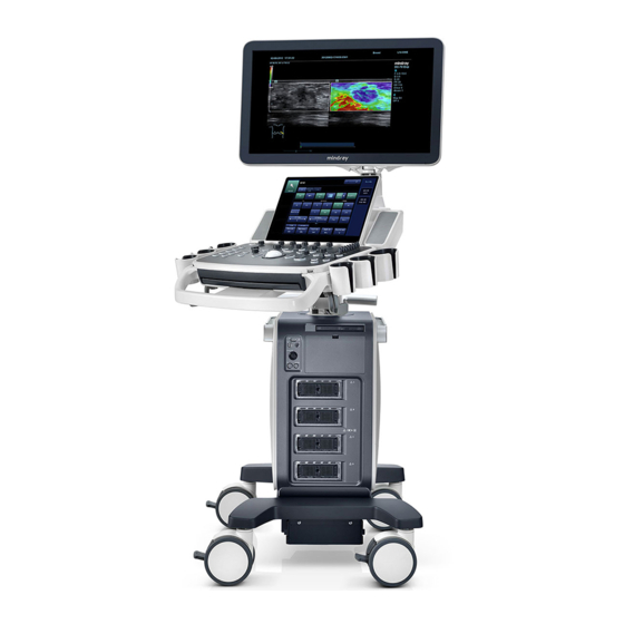
Specifications Overview 2.1.1 Intended Use The DC-70 series diagnostic ultrasound system is intended for use in clinical ultrasonic diagnosis. 2.1.2 Introduction of Each Unit Name Function Monitor Displays the images and parameters during scanning. Speaker Sound output. Touch screen panel Operator-system interface or control. - Page 20 Name Function Control panel adjusting Used for lifting or swiveling the control panel. lever Keyboard Used for typing characters or entering some functions. Main control panel Operator-system interface or control. USB_MIC port USB/MIC port Hanger Intracavitary probe Used for fixing the intracavitary probe. holder Ultrasound gel Used for placing the ultrasound gel or installing the gel warmer.
- Page 21 2.1.2.1 I/O panel Symbol Function <1> USB ports. <2> HDMI High definition multimedia interface. <3> Network port. <4> VGA signal output. <5> S-Video Used for separate video output. <6> Audio signal output port, left channel. Audio signal output port, right channel. <7>...
- Page 22 2.1.2.2 Power Supply Panel Name Function <1> Power outlet Supplies power to optional peripheral devices. <2> Power inlet AC power inlet. Equipotential terminal Used for equipotential bonding which balances the protective earth <3> potentials between the system and other electrical equipment. 2-4 Specifications...
- Page 23 2.1.2.3 Physio Panel Name Function <1> USB port Connects USB device. <2> Pencil probe port Used for connecting a pencil probe. <3> MIC port Used for connecting a microphone. Connects to ECG leads to directly obtain the patient's ECG ECG lead signal input signals.
- Page 24 2.1.2.4 Control Panel Name Description Power button <1> Press the button to turn on the system, the system enters the work status and the indicator becomes green. <2> Volume Adjust the volume. <3> <4> <5> Adjust the corresponding functions on the touch screen. <6>...
- Page 25 Name Description <13> End Exam End the current exam. <14> Text Enter/exit the textual comment status. <15> Clear Clear the comments or measurement caliper. Press to enter the Cine Review status from non-cine status when <16> Cine there is a multi-frame cine file playing. <17>...
- Page 26 Name Description <39> Move the trackball to change the cursor position. Confirm an operation. The function is same with the left-button of <40> the mouse. <41> Freeze Freeze/defreeze the image. <42> Save Save the image; user-defined key. <43> User-defined keys, functions of which can be defined in preset. <44>...
- Page 27 Keyboard Common functional keys Function Confirm the entered data, or move the cursor to the top of the next row of the Enter text or input field. Cancel the operation or exit. Jump to the next operable item. Back space Insert a space.
-
Page 28: Peripherals Supported
2.1.3 Peripherals Supported Item Model Black/white digital video SONY UP-D897, MITSUBISHI P95DW-N, SONY UP-D898MD, SONY printer UP-X898MD Color digital video SONY UP-D25MD printer HP Deskjet 1050 J410 series, HP Officejet 7000 wide format, HP Graph/text printer Officejet Pro 8100 Wireless printer HP Officejet Pro 8100 USB port: 971-SWNOM (2-pedal) Foot switch... -
Page 29: Monitor Specification
2.2.4 Monitor Specification 2.2.4.1 Main Monitor Dimension 19 inch,5:4 Resolution 1280×1024 Visible angle 120° left/right; 90° up/down 2.2.4.2 Touch Screen Dimension 10.4inch Resolution 800×600 Visible angle 140° left/right; 110° up/down Specifications 2-11... -
Page 31: System Installation
System Installation Preparations for Installation Do not install the machine in the following locations: NOTE: Locations near heat generators; Locations of high humidity; Locations with flammable gases. 3.1.1 Electrical Requirements 3.1.1.1 Requirement of Regulated Power Supply Power specification is showing in chapter 2.2.2. Due to the difference of the power supply stability of different districts, please advise the user to adopt a regulator of good quality and performance such as an on-line UPS. -
Page 32: Installation Conditions
Installation Conditions 3.1.2 3.1.2.1 Space Requirements Place the system with necessary peripherals in a position that is convenient for operation: 1. Place the system in a room with good ventilation or an air conditioner. 2. The door is at least 0.8m wide. The ultrasound machines can move into the room easily. 3. -
Page 33: Confirmation Before Installation
3.1.3 Confirmation before Installation Perform the following confirmation before installing the system: 1. The video format used in the region or country where the system is installed. 2. The language used in the region or country where the system is installed. 3. - Page 34 3. Remove the close carton box. Press the clasps down to release them. See the figure below: 4. Turn the monitor foam to the position as shown below: 3-4 System Installation...
-
Page 35: Check
2. Ensure there is no damage, indentation or cracks occurring to the machine. If any, please contact Mindray Customer Service Department. Installation of Main Unit To prevent the machine from damage, when you perform the following operations, NOTE: please lock the casters if the machine doesn’t to be moved... -
Page 36: Open Up The Monitor
3.3.1 Open up the Monitor Adjust the monitor to the position as shown in the figure below. NOTE: Take care of your hands when adjust the monitor up and down. 3.3.2 Connecting the Power Cord 1. Push the retaining clamp upward, and insert the power plug into the receptacle, as shown in the figure (a) below. -
Page 37: Connecting Ecg
3. Plug the other end power plug into an appropriate outlet. The grounding terminal should be connected with a power grounding cable to ensure that protective grounding works normally. Grounding terminal NOTE: Make sure to allow sufficient slack in the cable so that the plug is not pulled out of the wall if the system is moved slightly. -
Page 38: Connecting The Transducer
Clip 3.3.5 Connecting the Transducer Four sockets (A, B, C, D) are configured on the system; every socket can be connected with all types of supported transducers. 1. Keep the cable end of the transducer to the right side of the system, and insert the connector into the socket of the system, and then press in fully. -
Page 39: Installing Peripherals
3.3.5.1 Using the Probe Dust-proof Cover If a probe port is not used for a long period of time, please use the dustproof cover to protect the probe port from dust; otherwise bad contact may result. Transducer socket Dust-proof cover Installing Peripherals For the models of the supported peripherals, please refer to “2.1.3 Supported Peripherals”. - Page 40 As shown in the figure below, a graph / text printer has a power cord and data cable. The power cord shall be directly plugged into a well-grounded outlet. Power supply cable Data cable USB port 1. Connect the data cable to the USB port on the ultrasound system. 2.
- Page 41 6. Click [Have Disk…] to find the driver path (the installation type should be WIN7 64), and then click [Next] to install the driver. 7. Complete the operation according to the tips on the screen. Click [Finish] to end the installation. NOTE: 1.
-
Page 42: Installing Video Printer
In "[Setup]→[Print Preset]" screen, select the "Report Print" column in the service list. You can select printer from the driver list next to “Printer” in the lower screen and set the items in the "Property" box. Click [Save] after you have finished setting. Please refer to the accompanying manuals of the printers for more details. -
Page 43: Position A Printer
4. Add a wireless adapter, following the steps described in “Add network printer.” See chapter “3.4.2 Installing a Graph / Laser Printer.” 5. Open the [Setup] [Printer Preset] page, select “Report Print” from the printer list, select the printer to be Officejet Pro 8100, and set properties. 6. -
Page 44: Installing Barcode Scanner
3.4.6 Installing Barcode Scanner The system supports barcode reader to read the patient information (ID). 1. For structure of the scanner, see the figure below. The important parts are: LED indicator, scanning surface, and the switch. Scanning surface LED indicator Switch 2. -
Page 45: System Configuration
System Configuration 3.5.1 Running the System Connect the AC power; make sure the ultrasound system and other optional devices are correctly connected. When the AC power indicator on the control panel is light on (indicator is in green), press the power button on the control panel to turn on the system. -
Page 46: System Preset
3.5.3 System Preset 1. Press <F10> on the keyboard to open the Setup menu. 2. The system displays the System Preset screen. 3-16 System Installation... -
Page 47: Print Preset
The following settings can be performed on the System Preset screen. Item Region: preset the hospital name, date and time, and select the language. Key Config: preset the function of user defined keys (Print, Save, P, F3, F4, F5, F6 and F12) and the footswitch, key lightness, key volume and trackball speed can be adjusted. -
Page 48: Dicom/Hl7 Preset
3. Enter the name and password for this hotspot in the Hosted Network box. 4. Click [Start] to enable the function. 5. Use other devices to search and connect to this network. NOTE: Please do not switch [Disable Wifi]/[Enable Wifi] frequently. If [Start]/[Stop] button become available after frequent switching or the DC-70 can no longer search any other hotspots, please click [Disable Wifi] again and then click [Enable Wifi] to see if it works. - Page 49 Click [Add] to add the server to the list if the connection works normally. The following is an example: AE Title should be the same with the SCU AE Title preset in the server NOTE: (PACS/RIS/HIS). DICOM communication port should be the same with the one in the server. If the currently entered name has already existed, the system will pop up: “The server name exists!”...
- Page 50 When the system is configured with DICOM basic function module, and installed DICOM Worklist, MPPS, DICOM Structured Reporting and Query/ Retrieve modules, the corresponding preset settings can be found in DICOM Service screen. The DICOM Service Setting is used to set properties of DICOM services as Storage, Print, Worklist, MPPS, Storage Commitment and Query/ Retrieve.
-
Page 51: Check System Information
3.5.7 Check System Information In System Information screen, it displays the product configuration, the optional installation status, software version, hardware & boards, and driver related information. You can check the product information here. Press <Setup>, and then click [System Info] to open the following screen. On About Detail page, system hardware &... -
Page 53: Product Principle
Product Principle Hardware System Diagram Power Communication Physiological Signal Module Reset/Control/Clocks Battery TX/RX Clock Probe Battery Connector Management ATGC POUT(64) Probe Probe Battery Unit Signal Connector Sync Switch Data Data Probe Sampling FPGA FPGA PHV Control Connector Mini Brd Scan Status Front End Probe TR_A Board... -
Page 54: Ultrasound Front-End Unit
As the independent sub-module, 4D driving function and physiological signals are subordinate to the engine board. As an option, CW receiving function can be realized through an independent single board and is subordinate to TRA board signal. Back-end unit: more functions are achieved on back-end unit. -
Page 55: Probe Board
4.2.1 Probe Board TR Board POUT 128ch or 64ch Transmit & Receive POUT 128ch x4 (A-D) POUT switch ctrl 4D&TEE probe analog signals probe analog signals Analog signal Board e.g. 4D motor/TEE temperature & angle x4 (A-D) ctrl switch DC-DC Power Board ±PHV,±HV, 12V, 5V, 3.3V... -
Page 56: Cw Module
Beam data sends back to the engine board via the serial and the addition from one board to another. Engine board controls TR board via the asteroidal. Pen Probe TX/RX TR Board connect to TR_A slot Pencil Probe 64ch TX/RX Probe Board TX-RX switch present... -
Page 57: Engine Board
4.2.4 Engine Board Engine board is equipped with pre-processing of beam data, scanning generator, primary clock on front-end, ATGC circuit, probe management control, high-voltage switch control, etc. The board is also considered as the engine of ultrasound service. Engine Board 4D motor signals temperature / 4D&TEE... -
Page 58: Module
Response to the software control. The software configures DSP_FPGA’s register to complete the configuration on entire front-end via PCIE interface. TR control board. XCVR from DSP_FPGA controls each TR board respectively. Scanning generator. It is produced by DSP_FPGA. ... -
Page 59: Ecg Module
Figure 4-6 Schematic diagram of 4D&TEE module 4.2.6 ECG Module ECG test and PCG test can be achieved on ECG module. ECG module communicates with engine board via UART. Ultrasound Back-end Unit Taking PC module as the center, back-end unit is the platform of the ultrasound software system. It takes charge of back-end’s central control. -
Page 60: Pc Module
4.3.1 PC Module PC module aggregates CPU, iGPU (core graphics/integrated graphics), host bridge (IO extension), memory bank, network adaptor, etc. Together with PC carrier board and hard disk, as the calculation and control center of the entire unit, PC module fulfills the comprehensive functions on the computer system. -
Page 61: Io Interface Module
PCIE bus PC Carrier Board Global reset Configuration status Engine Brd JTAG (downwards) JTAG Ethernet HAD bus Audio Expansion PCIE HDMI, DDC IO Board VGA, DDC S-Video digital video Audio (L/R) JTAG (downwards) Configuration status Video Module S-Video Expansion Printer LPC bus Fans global reset... -
Page 62: Extension And Distribution
Extension and Distribution 4.4.1 Video Extension Function Video distribution plans of DC-70 product are: Primary display and secondary display both adopt DVI signals. PC carrier board offers DDC channel. It communicates with primary display, secondary display, VGA peripheral, HDMI peripheral. The display parameters, such as the brightness of primary display and secondary display and the contrast, are achieved on DDC channel. -
Page 63: Audio Interface
4.4.2 Audio Interface Audio interface plans of DC-70 product are: The speakers on the device support dual sound tracks of 10 W/8 Ω. Video output is from PC module; video input goes into PC module. Audio amplifier is accomplished on PC carrier board. 4.4.3 SATA Interface SATA is used for connecting the storage devices, including hard disk and DVD flash disk. -
Page 64: Network Interface
Carrier Board Mother Board Control Panel USB 1.1 Port 0 Keyboard USB 2.0 Controller Port 1 Touch Screen 01_OC User Port x2 PC Module VBUS USB 2.0 User Port Port 2 VBUS USB 2.0 User Port Port 3 VBUS OC_N 23_OC IO Board USB 2.0... -
Page 65: Pcie Interface Distribution
Wired network: is realized based on PC module (MAC+PHY) and isolation transformer of IO board. The network capability is decided by PC module. Isolation transformer and RJ45 network circuit have to meet the security requirements of creepage distance. ... -
Page 66: Power Supply Unit
Power Supply Unit Control System & Ultrasound Functions control control power control AC input AC input DC supply DC-DC Module AC-DC Module PHV Module AC Interface AC output AC input Module Devices Assistant Output Module AC output AC output Printer AC Unit DC Unit Power Unit... -
Page 67: Ac-Dc Module
Configuration 1 Configuration 2 Control System & Ultrasound Functions DC-DC Module PHV Module Control AC-DC Board Board Devices Battery Printer Assembly Fans Figure 4-12 Schematic diagram of power unit Configuration 1 is only set for power supply box (AC) before the 02.00.00(Rev 19070) (EGD019F) version. -
Page 68: Dc-Dc Module
4.5.2 DC-DC Module DC-DC module provides public power supply (for example, 12 V, 3.3 V) or specialized power supply (for example A± 5.7 V) to ultrasound service module. It meets the requirements of the voltage and the current. The service module is able to fulfill the switching of the power supply. 4.5.3 PHV Module PHV is the acronym of Programmable Height Voltage. -
Page 69: Primary Display Assembly
Various function keys, encoder. It is decided on industry design. White and orange backlights. Four adjustable levels for backlight’s brightness. Four adjustable levels for sound volume. 8-segment TGC slider. TCG assembly from DC-T6/N6 product. Provide the power supply to one gel heater: 12V@3A. ... - Page 70 The function of DC-70’s touch screen are: It coordinates with display area. Projected capacitive. Supports at least 2 touches. Power supply and the signal uses USB 1.1 standard. Used-definition of the connector. Anti-glare. 4-18 Product Principle...
-
Page 71: Function And Performance Checking Method
Function and Performance Checking Method NOTE The chapter supplies the detailed method for product main function and performance checking. This is used for referring or studying by engineer but not required. System Running Status 5.2.1 Running Status 1. Normal power on/off operation (duration time is normal), no abnormal sounds or phenomena occur during normal operation. -
Page 72: General Exam
General exam 5.3.1 Check Flow 5.3.2 Checking Content 5.3.2.1 Check Control Panel Procedure Checking standard Check all buttons, keys and knobs All keys and knobs are effective. Follow the direction: left to right, and up to down. Function checking of the trackball: The trackball can be rotated easily;... - Page 73 5.3.2.2 Check the Monitor Procedure Standard Press “+”, the brightness increases; and press “-”, the Adjust LCD brightness brightness decreases. Adjust LCD contrast Press “+”, the contrast increases; and press “-”, the Enter [Preset]->[General], click contrast decreases.
- Page 74 5.3.2.5 Check Peripherals Procedure Standard Footswitch: Press the freeze key (the right key), image is frozen, the freeze menu is displayed; press the Connect footswitch; check key again, image is unfrozen. functions of footswitch according to the functions listed in Key Config. (e.g. right Press the print key (middle key), color printing key- image frozen, middle key- color print, starts.
-
Page 75: Function Checking
Function Checking NOTE: A complete function inspection is described here, do the checking according to the actual system configuration. 5.4.1 Checking Flow 5.4.2 Content 5.4.2.1 Imaging Modes 1. B mode In B Mode scanning, the image parameter area in the upper left corner of the screen will display the real-time parameter values as follows: Parameter iClear... - Page 76 Procedure Checking criteria Press <B> button. Enter B mode image. B mode interface appears. Gain adjustment G Gain increases with rotating the knob clockwise; Rotate <B> button Gain decreases with rotating the knob anticlockwise; Depth adjustment D The depth of the image changes accordingly. Depth range varies depending upon the probe types.
- Page 77 Dynamic Range The adjusting range of parameter is 30-180 dB in increments of 5 image touch screen-[Dynamic Range]. iClear The system provides 7 levels of iClear effects adjustment, Off represents iClear is disabled, and the bigger the value is the B image touch screen-[iClear].
- Page 78 Echo Boost [Echo Boost] is enabled when it is on in B mode. (Highlighted) the B image touch screen-[Echo system is in “Echo Boost” status. Boost]. 2. M mode In M mode scanning, the image parameter area in the upper left corner of the screen displays the real-time parameter values as follows: Parameter Meaning...
- Page 79 5. PW/CW mode The parameters will be displayed in the image parameter area on the left part of the screen as follows: Display Angle Frequency Gain Pulse SV Size Angle Parameters Repetition (Wall Position (only CW ) Frequency Filter) ...
- Page 80 When the value is 0, the system exits auto play mode. Move the cursor onto the desired start point of the Set the start point of cine loop. cine loop, click [Set First Frame] in the menu or soft menu to set the start point. Move the cursor onto the desired end point of the Set the end point of cine loop.
-
Page 81: Performance Test
Press <End Exam> during image scanning Press <Review> key. The system enters into image review mode. Click [Exit] on the Review screen; or, press The system exits image review mode. <Review> again, or, press <Esc> key ... - Page 82 Scanning techniques: contact the probe with the acoustic window of the phantom, no spacing nor pressing. Tips: For the testing phantoms, please refer to Appendix B. KS107BD is low frequency phantom and used when Probe focus frequency is less than 4MHZ; KS107BG is high frequency phantom and used when Probe focus frequency is more than 5MHZ;...
- Page 83 the scan surface, making the longitudinal resolution testing targets to be displayed around the midline of the image. Adjust the focus point focuses at the position where the longitudinal resolution testing targets are displayed. Adjust parameters like gain, dynamic range, TGC, making the background tissue unseen, just displaying the target image clearly.
- Page 84 Record the depth of the furthest target (the target can be seen clearly). NOTE: Increasing the gain will also increase the noise, and echo may be covered. When using a linear probe, please completely contact the probe with the scan surface, no side clearance is allowed.
- Page 85 5.5.2.3 Geometric positioning accuracy Longitudinal geometric positioning accuracy Test Step: Do adjustments as the way in testing the maximum depth. Record the distance by 20mm each segment on the longitudinal targets line using the measurement caliper; Select the value with the greatest error (to 20mm), calculate the accuracy using the formula below The measurement caliper should be positioned at the upper edge of the NOTE:...
- Page 86 Record the distance by 20mm each segment on the transverse targets line by using the measurement caliper Select the value with the greatest error (to 20mm), calculate the accuracy by using the formula below NOTE: When using a linear probe, record the transverse distance by segment. When using a convex probe, all transverse targets should be displayed integrally in an image.
- Page 87 5.5.2.4 Blackout Area Test Step: Cover the scan surface of the phantom with water or couple gel, gently contact the probe with the scan surface Adjust the depth at a lower value, and set the focus at the nearest place to the scan surface. Decrease the value of parameters like AP, Gain until the background noise just can be seen.
-
Page 89: Software Installation &Maintenance
Software Installation &Maintenance Enter Maintenance NOTE: Before the maintenance operation, the engineer should login the system with the account of Service. Login: 1. When Access Control is disabled: press [ctrl]+[/] to open the login dialogue box and select Service as the user name. If Access Control is enabled, log in as the admin first and then press [ctrl]+[/] to see the Service in User Name. -
Page 90: Set Installment
Set Installment If the customer purchases the product with the installment, the service can set installment and the installment password will be generated by the system automatically. NOTE: Log on the system with the identity of Service before perform system maintenance. Press [Setup]. - Page 91 First installment password: After the user paying off the down payment, the installment dialog box appears after turning on the device. Enter this password in “Period Password”, and click “Start” to log in the system. Note: after the user pays off the down payment and enters the first installment password, the system starts to calculate next installment time.
-
Page 92: Software Installation/Restoration
Do Not cut off, shut down or restart the system in the process of restoration. Enter Windows 1. Open [Enter Windows] to enter the interface to set the password (website: http://apollo.mindray.com/ukmo/). The following dialog box appears after clicking Make Pwd icon. 6-4 Software Installation &Maintenance... -
Page 93: Software Maintenance
2. Type device’s Mac address and serial number (see System Information). The password of Mac address to Windows system is created after clicking Make Pwd. 3. Enter maintenance menu. Click [Enter Windows]. Type the password to enter Windows system. Software Maintenance 6.5.1 Export Log 1. -
Page 94: Patient Data Backup And Restoration
6.6.1.1 Back up the Setup Data 1. Click [Export] to open the Export Data dialogue box. 2. Select the path to save data. 3. Click [OK]. A progress bar appears and the setup data of the selected item is exported to the specified path. - Page 95 6.6.2.2 Restore Backup Patient Data 1. Press [iStation] on the keyboard to open the iStation dialogue box; 2. Select the drive which contains the patient data. Click [Select All Exams] to select all data or select the patient data to be restored one by one. Click [Restore] to restore the patient data from the current drive to the patient database.
-
Page 96: Introduction On Hard Disk's Partitions
Introduction on Hard disk's Partitions The entire capacity of the system hard disk is 128 GB. The details are shown as follows: NOTEs Blocks(G) NOTEs NTFS <261G NTFS NTFS Data distribution on each drive is shown as follows: 1. -
Page 97: Adjustments
Adjustments Monitor Adjustment 7.1.1 Position Adjustment Gently hold the bottom edge of the monitor when adjusting its position. Height adjustment Move the monitor support arm up or down to adjust the height. NOTE: Take care not to trap your hands when adjusting the monitor up and down. ... - Page 98 Tilt the monitor When positioned vertically, the monitor can be tilted 20° backward and can be tilted forward to a horizontal position. When transporting or moving the system, keep the monitor in the horizontal position, as shown below: Lock the monitor To move the machine a short distance, install the protective foam (provided in the packaging) onto the monitor, adjust the monitor and supporting arm to the middle position, and then lock...
-
Page 99: Brightness And Contrast Adjustment
7.1.2 Brightness and Contrast Adjustment Monitoring the brightness and contrast adjustment is one of the most important factors for proper image qualities. If set incorrectly, the gain, TGC, dynamic range or even acoustic output have to be changed more often than necessary to compensate. The adjusting buttons are shown as follows: ... -
Page 100: Monitor Test
NOTE: On the monitor, the brightness adjustment comes before contrast. After readjusting the monitor’s contrast and brightness, adjust all preset and peripheral settings. 7.1.3 Monitor Test 1. Log on as the "Service"; refer to chapter 6.1 for details. 2. Press the [F10] key on the keyboard to enter setup menu, and click [Maintenance] to enter the screen. - Page 101 Item Description The screen displays a white strip in the middle while the above and below Contrast are black, if the boundary of black and white is clear, the test is passed; Press [Set] to switch between the 2 interfaces, and it's required that the black Resolution and white strips in the middle or around are clear, while the adjacent strips can be distinguished to pass the test;...
- Page 102 Press [Set] to enter pure color interfaces of green, blue, red, black and white. Observe the LCD screen. Check bright point and dark point in the black and white interfaces. Criterion for pass: bright point number is 0; number of continuous dark point pair is ≤3, and no continuous dark point appears in the BadPoint image area;...
-
Page 103: Monitor Parameter Setting
7.1.4 Monitor Parameter Setting NOTE: After changing the main monitor, parameter loading should be performed to match the monitor and the system. The parameters of the main monitor include color temperature. Information of loading Default parameters are introduced here: Press <1> and <4> key on the monitor as shown in the figure for more than 3 seconds to enter the screen. -
Page 104: Touch Screen Test
7.2.2 Touch Screen Test 1. Log on as the "Service"; refer to chapter 6.1 for details. 2. Press the [F10] key on the keyboard to enter setup menu, and click [Maintenance] to enter the screen. 3. Click [Setup] and select [Test Touch Screen] to enter the screen, test methods are the same as in main screen test. - Page 105 Control lever Key backlit brightness adjustment In the [System Preset]→[Key Config] page, you can adjust key backlit brightness and volume. Functional keys setting In the [System Preset]→[Key Config] page, you can preset functions for keys of <Print>, <Save>, <P>, <F3>, <F4>, <F5>, <F6>, <F12>, for example, you can preset save image to hard drive function of F3.
-
Page 106: Caster Adjustment
Caster Adjustment There are four braking casters of the main unit, as shown in the figure: tread the 2 “On” button downwards by foot to lock the caster, tread the 1 “Off” button downwards by foot to release the caster. When locking or releasing the casters, move the casters if necessary. RELEASING LOCKING 7-10 Adjustments... -
Page 107: Field Replaceable Unit
Field Replaceable Unit The detailed information of Field Replaceable Unit is as follows: Classification Description Order Number Figure Comments Disassembly PC carrier board (spare 115-025757-00 9.3.10 part) Main unit Compatibility remarks: related 115-041021-00 When using Old PC module, the (old PC software version should be: module) - Page 108 Classification Description Order Number Figure Comments Disassembly 2123 TR64 115-041016-00 9.3.11 board 2123 engine 115-041017-00 9.3.11 board Transducer board 115-041018-00 All four sockets are 256 pin 9.3.2 assembly 8-2 Field Replaceable Unit...
- Page 109 Classification Description Order Number Figure Comments Disassembly Mother board 115-025763-00 9.3.14 assembly With bracket IO module 115-025764-00 9.3.6 This module should match with the WIFI Module Kit 115-039264-00 This module should match with WIFI Module Kit (EWM-W163M201E) IO Board 115-051521-00 115-051210-00 Assembly(FR 9.3.6...
- Page 110 Classification Description Order Number Figure Comments Disassembly HDD(DC-70/C 115-025779-00 E/spare part) HDD(DC-70T/ CE/spare 115-025780-00 part) HDD(DC-70 Pro /CE/spare 115-025781-00 part) HDD(DC-70 115-025782-00 /CE/spare part) Remark model, software version and HDD(DC-70 regulation type Vet /CE/spare 115-025783-00 part) Compatibility remarks: 9.3.7 HDD(DC-75/C...
- Page 111 Disassembly HDD(DC-70 115-033483-00 /FDA/spare part) HDD(DC-70 115-042974-00 /FDA/spare part) HDD(DC-70/C E/FRU/NEW 115-042929-00 HDD(DC-70T/ 115-042930-00 FRU/NEW HDD(DC-70 115-042931-00 /CE/FRU/NE Remark model, software version and W PC) regulation type HDD(DC-70 Compatibility remarks: 115-042932-00 It is only applied for the machine with new /CE/FRU/NE PC module.
- Page 112 Classification Description Order Number Figure Comments Disassembly HDD(DC-78/C E FRU/NEW 115-042942-00 HDD(DC-70 /FDA/FRU/NE 115-042934-00 W PC) HDD(DC-70T/ FDA/FRU/NE 115-042935-00 W PC) HDD(DC-70 115-042936-00 /FDA/FRU/NE W PC) HDD(DC-70 115-042937-00 /FDA/FRU/NE W PC) HDD(DC-70S /FDA/FRU/NE 115-048193-00 W PC) HDD(DC-75 /FDA/FRU/NE 115-048194-00 W PC)
- Page 113 Disassembly W PC) Hard disk(DC-70S/ 115-049538-0 CE/FRU/NEW Hard disk(DC-70/R 115-049537-00 ussia/FRU/NE W PC) Hard Disk(DC-70T/ 115-049916-00 Russia/FRU/N EW PC) Hard Remark model, software version and Disk(DC-70 regulation type 115-049917-00 Pro/Russia/F It is only used for Russia machine. RU/NEW PC) Hard...
- Page 114 Classification Description Order Number Figure Comments Disassembly 4D module 115-042870-00 Support maintenance and upgrade 9.3.19 package Including pencil probe cable CW module 115-024664-00 9.3.20 package Support maintenance and upgrade The vision of the software with wireless net adapter: OS version: V3.0 or higher WIFI Module 115-039264-00 9.3.6...
- Page 115 Classification Description Order Number Figure Comments Disassembly The version of the software with wireless WIFI Module net adapter: 115-051210-00 OS version: V4.0 or higher 9.3.6 (EWM-W163 This assembly should match with IO Board M201E) Assembly(FRU) 115-051521-00 Inlet fan 115-042896-00 9.3.13 assembly Field Replaceable Unit 8-9...
- Page 116 Classification Description Order Number Figure Comments Disassembly Outlet fan 115-042898-00 9.3.4 assembly assembly 115-025791-00 9.3.12 (spare part) Control panel support 115-025792-00 9.3.22 assembly (spare part) 8-10 Field Replaceable Unit...
- Page 117 Classification Description Order Number Figure Comments Disassembly Display supporting 115-025793-00 arm assembly (spare part) 9.3.23 17"LCD It is only used for Russia’s DC-70S Monitor 115-033337-00 Support machine. Arm(FRU) Monitor Monitor assembly 115-044283-00 9.3.1 related (FRU/LG) Field Replaceable Unit 8-11...
- Page 118 Classification Description Order Number Figure Comments Disassembly 17"Monitor It is only used for Russia’s DC-70S Assembly(FR 115-033331-00 machine. Keyboard assembly 115-025765-00 Including label (FRU) 9.3.15 Control Keyboard panel It is only used for Russia’s DC-70S Assembly(212 115-049529-00 related 3/FRU/Russia machine. DC-70S) Encoder Board...
- Page 119 Classification Description Order Number Figure Comments Disassembly 2'' Trackball 023-001157-00 No cables 9.3.15.2 assembly TGC board 801-2119-0002 No cables 9.3.15.3 (spare part) 9-00 Small keyboard 115-025772-00 assembly (FRU) 9.3.24 Small Keyboard 115-049536-00 It is only used for Russia machine. Assembly(Ru ssia/FRU) Touch screen assembly...
- Page 120 Classification Description Order Number Figure Comments Disassembly Touch screen assembly 115-025767-00 (DC-70T/spar e part) Touch screen assembly 115-025768-00 (DC-70S/FRU Touch screen assembly 115-025769-00 (DC-70 Pro/spare part) Touch screen assembly 115-025770-00 (DC-70 Exp/spare part) Touch screen assembly 115-025771-00 (DC-70 Vet/spare part)
- Page 121 Classification Description Order Number Figure Comments Disassembly assembly (DC-78/spare part) Gel warmer holder 115-024667-01 package Including power input assembly, AC-DC Power board, control switch board, the fan of box(FRU/ 115-043058-00 power box. POWER) It can be replaced as a whole unity. Power input Select the proper label according to the assembly(212...
- Page 122 Classification Description Order Number Figure Comments Disassembly 2123 Control Switch It is only applied for the machine with new Board(FRU / 115-043056-00 9.3.26 power assembly. POWER) 2123 AC-DC Board(FRU / It is only applied for the machine with new 115-042951-00 9.3.27 power assembly.
- Page 123 Classification Description Order Number Figure Comments Disassembly PHV power 115-023068-00 9.3.9 Board (FRU) 2123 battery management 115-041019-00 9.3.5 board Lithium battery Including battery, battery management assembly board, charging/signal cable and metal 115-024663-00 9.3.5 (packaged enclosure, support maintenance and alone/SFDA/C upgrade Field Replaceable Unit 8-17...
- Page 124 Classification Description Order Number Figure Comments Disassembly N3 speaker 115-015309-00 9.3.16 assembly Caster (spare 115-025796-00 Wrench attached 9.3.18 part) 8-18 Field Replaceable Unit...
-
Page 125: Structure And Assembly/Disassembly
Structure and Assembly/Disassembly Structure of the Entire System Structure and Assembly/Disassembly 9-1... -
Page 126: Preparation
N-206S 095-000077-00 Anti-electrostatic glove: 1 pair. 9.2.2 Engineers Required The disassembly should be performed by professionals from Mindray or the staff who are qualified for the maintenance after the training. 9.2.3 Disassembly Requirements Be prepared before disassembling ultrasound device. 1. Stop scanning the patient and capturing images. Shut down the device and cut off AC power supply. -
Page 127: Assembly/Disassembly
Assembly/Disassembly This section describes the disassembling and the assembling of the main modules and hardware boards. The assembling is the inverse process of the disassembling if not mentioned in particular. Sketch Left side panel Air intake Digital Air offtake DC module PC module board... -
Page 128: Display (Monitor) Assembly
9.3.1 Display (Monitor) Assembly The disassembly tool: cross-headed screwdriver (M3, M4) 1. Unscrew two M4X12 screws, and remove the display cable cover; 2. Unscrew three M4 X 12 screws. Remove the power supply cable of the display and unplug the signal cable. -
Page 129: Probe Board Assembly
Unscrew two PT3X8 screws locking the adjustable key board, and then remove the adjustable keyboard assembly. Unscrew eight M3X8 screws on the cassette mechanism assembly and front cover, and then remove the front cover assembly of the monitor. 9.3.2 Probe Board Assembly The disassembly tool: cross-headed screwdriver (M3, M4) Unscrew the M4 X 8 screw on middle part of left side panel’s lower position. - Page 130 2. Follow the procedures of step 1 to remove right side panel. 3. Unscrew two M4 X 8 screws fixing the front cover, and remove the front cover upwards. 4. Unscrew twelve M4 X 8 screws. Hold two plastic handles on the probe board. Pull the probe board assembly out.
-
Page 131: Disassembling Ecg Assembly
1. Because of the socket of the probe board lying on the left side, please use even NOTE: strength when pulling out it. 2. There are two bolts on the probe board assembly. Snap the assembly into place after inserting the bolts, and then fix the screws. 9.3.3 Disassembling ECG Assembly The disassembly tool: cross-headed screwdriver (M3, M4), diagonal cutting pliers. -
Page 132: Outlet Fan
4. Unscrew three M4 X 8 screws fixing ECG assembly, and pull ECG assembly out. 9.3.4 Outlet Fan The disassembly tool: cross-headed screwdriver (M3, M4), anti-electrostatic glove 1. Follow step 1 in Chapter 9.3.2 to remove left side panel. 2. Unscrew two M4 X 8 screws fixing the frame of the fan. Hold the metal handle to pull the fan assembly out. -
Page 133: Disassembling Battery Assembly
4. Unscrew two M3 step screws fixing PCBA, and remove fan PCBA. Pull out of the fan socket to remove the fan. See the figure. 9.3.5 Disassembling Battery Assembly The disassembly tool: cross-headed screwdriver (M3, M4), diagonal cutting pliers, anti-electrostatic glove. - Page 134 3. Release the clasp and pull out the plug. Unscrew three M4 X 8 screws to remove the battery assembly. 4. Unscrew four M3 X 8 screws to part the battery assembly to top cover and bottom cover. 9-10 Structure and Assembly/Disassembly...
- Page 135 5. Take off the battery from the top cover of the battery compartment. 6. Take off the battery PCBA from the top cover of the battery compartment. Structure and Assembly/Disassembly 9-11...
-
Page 136: Io Board/Wifi Board
9.3.6 IO Board/WIFI Board The disassembly tool: cross-headed screwdriver (M3, M4), anti-electrostatic glove 1. Follow step 1 and step 2 in Chapter 9.3.2 to remove left and right side panels. 2. Unscrew two M4 X 8 screws fixing the rear cover, and remove the rear cover. 3. - Page 137 5. Flick the elastic sheet up with two fingers, and remove WIFI board. 6. Pull two plugs out. Insert the plug into the black hole. 7. Pull it upwards to remove the cable board. Structure and Assembly/Disassembly 9-13...
-
Page 138: Hdd
8. Unscrew seven M3 X 8 screws to remove IO board. 9.3.7 HDD The disassembly tool: cross-headed screwdriver (M3, M4), anti-electrostatic glove 1. Follow step 1 and step 2 in Chapter 9.3.2 to remove left and right side panels. 2. Unscrew two M4 X 8 screws fixing the rear cover, and remove the rear cover. 9-14 Structure and Assembly/Disassembly... - Page 139 3. Unplug the power supply cable connecting hard disk assembly to the mother board and the plug of SATA signal cable. 4. Unscrew three M4 X 8 screws fixing the hard disk to remove the hard disk assembly. 5. Pull the power supply cable of the hard disk and SATA signal plug out. Unscrew 2 M3 X 8 screws on two sides to remove the hard disk.
-
Page 140: Electronic Assembly On The Base
9.3.8 Electronic Assembly on the Base The disassembly tool: cross-headed screwdriver (M3, M4) 1. Follow step 1 and step 2 in Chapter 9.3.2 to remove left and right side panels. 2. Unscrew two M4 X 8 screws fixing the rear cover, and remove the rear cover. 3. -
Page 141: Dc Box Assembly
4. Unscrew one M4 X 8 screw fixing the grounding terminal. Unscrew one M4 X 8 screw fixing the electronic on the base. Pull the electronic out. NOTE: If the metal plate holds the electronic assembly back, lift it upwards to pull it out. 9.3.9 DC Box Assembly The disassembly tool: cross-headed screwdriver (M3, M4), anti-electrostatic glove... -
Page 142: Pc Assembly
4. Unscrew five M3 X 8 screws on both sides to remove PCBA bracket assembly. NOTE: Take notice of the bolts on the socket when installing. 5. Unscrew eight M3 X 8 screws on metal bracket to remove DC board. 6. - Page 143 2. Unscrew four M4 X 8 screws on the device (one is on the top; the other is at the bottom). Then, remove PC box assembly. 3. Unscrew five M3 X 8 screws on both sides to remove the metal cover. 4.
-
Page 144: Engine Board And Tr Board
5. Unscrew eight M3 X 8 screws on metal bracket to remove digital board. 6. Unscrew five M2.5 X 20 screws on digital board to remove PC module assembly. 9.3.11 Engine Board and TR Board The disassembly tool: cross-headed screwdriver (M3, M4), anti-electrostatic glove Follow step 1 in Chapter 9.3.2 to remove the left side panel. -
Page 145: Dvd
Release two plastic clips by hands to remove the engine board and TR board. TR board Engine board 9.3.12 The disassembly tool: cross-headed screwdriver (M3, M4), diagonal cutting pliers. 1. Follow step 1 to step 3 in Chapter 9.3.2. Remove the left/right side panels and the front cover. 2. -
Page 146: Inlet Fan
5. Unscrew two M3 X 6 screws on the back of DVD assembly to remove DVD cables. 6. Unscrew four M2 X 4 screws on DVD bracket assembly to remove DVD. 9.3.13 Inlet Fan The disassembly tool: cross-headed screwdriver (M3, M4), anti-electrostatic glove 1. -
Page 147: Motherboard
4. Unscrew two M3 step screws fixing PCBA, and remove fan PCBA. 5. Pull out of the fan socket to remove the fan. 9.3.14 Motherboard The disassembly tool: cross-headed screwdriver (M3, M4), diagonal cutting pliers, anti-electrostatic glove. 1. Follow step 1 to step 3 in Chapter 9.3.2 to remove the left/right side panels and the front cover. 2. - Page 148 6. Unplug the cables on the motherboard. Unscrew five M3 X 8 screws to remove the shield of the mother board upwards. Be careful with the electronics on the mother board. 7. Unscrew ten M3 X 8 screws to remove the shield of the mother board upwards. Be careful with the electronics on the mother board.
-
Page 149: Control Panel Assembly
9.3.15 Control Panel Assembly The disassembly tool: cross-headed screwdriver (M3, M4), diagonal cutting pliers, anti-electrostatic glove. 1. Remove the holders on both sides. Press the clips inwards. Lift the holders to both sides to remove them. Press the clips inwards 2. - Page 150 3. Lift the upper cover up around the margin. Disconnect all plugs on the upper cover. The control panel and the main unit fall apart then. 4. Unscrew the M3 X 8 screw on the cast-aluminum base to remove the control panel assembly. Operate the following procedures to remove the control panel assembly.
- Page 151 NOTE: To avoid incorrect installation, please take notice of the size of caps. 2. Unscrew nine PT4 X 10 tapping screws from the encoder board. Disconnect the plug connecting the encoder to the keyboard to remove the encoder assembly. 9.3.15.2 Trackball The disassembly tool: cross-headed screwdriver (M3, M4), anti-electrostatic glove...
- Page 152 Unscrew four PT3 X 10 tapping screws fixing TCG board. Disconnect the plug connecting TCG board to keyboard to remove TCG board and the silicon. 9.3.15.4 Buzzer The disassembly tool: cross-headed screwdriver (M2). Unscrew two PT2 X 6 tapping screws and gaskets to remove the buzzer. Disconnect the plug of the buzzer to remove it.
- Page 153 9.3.15.6 Support Mat The disassembly tool: cross-headed screwdriver (M3, M4), anti-electrostatic glove Unscrew five PT3 X 10 tapping screws from the support mat to remove it. 9.3.15.7 Upper Cover of the Keyboard and Control Panel Board The disassembly tool: cross-headed screwdriver (M3, M4), anti-electrostatic glove Remove the encoder assembly, trackball assembly, TGC board and the buzzer.
-
Page 154: Face Cover Assembly Of The Speaker/Speaker
9.3.15.8 Touchscreen Assembly The disassembly tool: cross-headed screwdriver (M3, M4). Unscrew four M4 X 12 SEMS screws from the touchscreen to remove it. The connecting cables lie behind the rear cover of the touchscreen. Be careful of NOTE: the cables when removing the assembly. 9.3.16 Face Cover Assembly of the Speaker/Speaker The disassembly tool: cross-headed screwdriver (M3, M4). - Page 155 2. Unscrew four M3 X 8 SEMS screws from the speaker to remove it. Disconnect the cables connecting the speaker to the main unit to remove the speaker assembly. Same procedures to remove right assembly. NOTE: To avoid incorrect installation, please take notice of the position of the speakers. 9.3.17 Intra-cavity Probe Holder...
-
Page 156: Caster
9.3.18 Caster The disassembly tool: open-ended spanner. Lock four casters of the device (step the caster “ON” downwards). Incline the device for 30 degrees. Use the spanner to lock the stud and turn the spanner clockwise to remove the caster. 9.3.19 4D Module Package The disassembly tool: cross-headed screwdriver (M3, M4), anti-electrostatic glove... - Page 157 2. Unscrew four M4 X 8 screws to remove the metal cover. 3. And remove engine board as shown in the figure below. Structure and Assembly/Disassembly 9-33...
-
Page 158: The Material Package Of Cw Assembly
4. Unscrew four M3 X 8 screws, and remove the material package of 4D module. 9.3.20 The Material Package of CW Assembly The disassembly tool: cross-headed screwdriver (M3, M4), anti-electrostatic glove 1. Follow step 1 in Chapter 9.3.2 to remove left side panel. 2. -
Page 159: Support Arm Assembly Of The Control Panel
3. And remove TR board as shown in the figure below. 4. Unscrew two M3 X 8 screws to remove the material package of CW assembly. 9.3.21 Support Arm Assembly of the Control Panel The disassembly tool: cross-headed screwdriver (M3, M4), sharp nose pliers, flat nose pliers. 1. - Page 160 Press the clips inwards. 2. Unscrew eight M4 X 12 screws on the control panel assembly. 3. Lift the upper cover up around the margin. Disconnect all plugs on the upper cover assembly. The control panel assembly and the main unit fall apart then. 4.
- Page 161 5. Unscrew four M4 X 12 combination screws from the touch screen assembly to remove it. 1. Unfasten the screw, and then remove the bolt. Take the guide cable out of the slot. 2. Disassemble the two parts as shown in the following figure. Take the cylinder-shaped part out of the dragline.
- Page 162 3. Unscrew four M4 X 12 screws around the loudspeaker. 4. Remove the cover of the loudspeaker. Disconnect the black plugs. The loudspeakers appear symmetrical. 5. Remove the cable clasp. 9-38 Structure and Assembly/Disassembly...
- Page 163 6. Unscrew six M6 X 20 screws on the flange plate. 7. Remove the frame of the keyboard. Rotate the white plastic circle on the mechanical arm to remove the white plastic circle. 8. Unscrew six M6 X 20 screws. Take the data cable out of the inner to remove the support arm assembly of the control panel.
-
Page 164: Support Arm Assembly Of The Display
9.3.22 Support Arm Assembly of the Display The disassembly tool: cross-headed screwdriver (M3, M4, M10). 1. Unscrew two M4X12 screws, and remove the display cable cover; 2. Unscrew three M4 X 12 screws. Remove the power supply cable of the display and unplug the signal cable. - Page 165 The metal part is inserted in the hole of the plastic part. The damage of the display’s Note: rear cover may occur if removed by force. 4. Unscrew six M4 X 12 screws. 5. Remove semicircle-shaped cover. 6. Remove the holders on both sides. Press the clips inwards. Lift the holders to both sides to remove them.
- Page 166 Press the clips inwards. 7. Unscrew eight M4 X 12 screws on the control panel assembly. 8. Lift the upper cover up around the margin. Disconnect all plugs on the upper cover. The control panel and the main unit fall apart then. 9-42 Structure and Assembly/Disassembly...
- Page 167 9. Unscrew the M3 X 8 combination screw on the cast-aluminum base to remove the control panel assembly. 10. Unscrew four M4 X 12 combination screws from the touchscreen assembly to remove it. 11. Unscrew two M4 X 12 screws. 12.
- Page 168 13. Cut off the black cable ties. 14. Unscrews the screws. Remove the white cable ties. 15. Take the grey cable out with forcing the arm downwards. 16. Unscrews an M10 screw. 9-44 Structure and Assembly/Disassembly...
-
Page 169: Keyboard Assembly
17. Pull the clasp out. Lift the mechanical arm upwards to remove it. 9.3.23 Keyboard Assembly Push and release the keyboard. Unscrew four M4 X 12 screws to remove the keyboard. 9.3.24 Power Input Assembly The disassembly tool: cross-headed screwdriver (M3, M4), anti-electrostatic glove 1. - Page 170 2. Unscrew two M4 X 12 screws. 3. Pull the power supply module; unscrew the screw to pull the whole assembly. 4. Unscrew five screws to remove AC-DC module. 5. Unscrew the screws and disconnect the plug as shown in the figure. 9-46 Structure and Assembly/Disassembly...
-
Page 171: Control Switch Board
6. Unscrew four M4 X 12 screws to obtain the power input assembly. 9.3.25 Control Switch Board The disassembly tool: cross-headed screwdriver (M3, M4), anti-electrostatic glove Follow step 1 to step 4 in Chapter 9.3.24 Power Input Assembly. Unscrew four screws and disconnect the plug; then unscrew 6 screws and remove control switch board. -
Page 172: Fan (Ac-Dc Fan)
9.3.27 FAN (AC-DC Fan) The disassembly tool: cross-headed screwdriver (M3, M4), anti-electrostatic glove Follow step 1 to step 4 in Chapter 9.3.24 Power Input Assembly. Unscrew two screws to remove the front cover of AC-DC module. Unscrew eight screws; then unplug the cable connecting fan assembly to control switch board to remove fan (two fans can disassemble separately). -
Page 173: Optional Installation/Assembly
Optional Installation/Assembly 10.1 Installing Optional Software Copy optional key file to USB flash disk and plug USB flash disk to the port. Open Setup menu. Select [Maintenance]-[Option]. Select the software package to be installed from the list. Click [Install]. Select key file from the dialog box, and then click [OK]. Select more than 1 option from the list and click [Batch Install] to install more than 1 option. - Page 174 NOTE: After all modules are installed, please go to the previous interface to confirm. Promote 1. Click [Promote]. The following image appears: Note: the promotion function is only applied to the uninstalled key. If the optional key is installed, the promotion function is disabled. Select the key to be promoted.
- Page 175 Uninstall 4. Select the software package to be uninstalled from option list. 5. Click [Uninstall] and the Confirm dialogue box opens. Click [OK]; 6. Return to the system preset interface. The option status changes into Uninstalled. The uninstall function is exclusive to internal users. The service engineers must NOTE: log in the system with the account of Service, and then conduct the uninstall.
- Page 176 10.2 Installation of Optional Devices to Hardware Hardware configuration list the product supports is displayed as shown below: Installation Material No. Descriptions Material and pictures reference 10.2.1 115-022764-00 ECG assembly 10.2.2 115-022765-00 Battery assembly CW assembly 10.2.3 115-022767-00 (including pencil probe cable) 115-039264-00 WIFI Module Kit...
- Page 177 10.2.5 115-022768-00 4D assembly 10.2.1 ECG Assembly The disassembly tool: cross-headed screwdriver (M3, M4). 1. Remove the left/right side panels and the front cover (refer to chapter 9.3.2). 2. Unplug MIC cables of front output panel, and release the clasp. 3.
- Page 178 4. Fix three M4 X 8 screws on ECG assembly and assemble ECG. 5. Install the output board, left/right side panels and front cover in reverse order. 10-6 Optional Installation/Assembly...
- Page 179 10.2.2 Battery Assembly The disassembly tool: cross-headed screwdriver (M3, M4), anti-electrostatic glove 1. Remove the left/right side panels (refer to chapter 9.3.2). 2. Unscrew two M4 X 8 screws fixing the rear cover, and remove the rear cover. 3. Fix three M4 X 8 screws. Add the clasp. Plug the cables and assemble the battery assembly. 4.
- Page 180 5. Install left/right side panels and rear cover in reverse order. 10.2.3 CW Board The disassembly tool: cross-headed screwdriver (M3, M4), anti-electrostatic glove 1. Follow step 1 in Chapter 9.3.2 to remove the left side panel. 2. Moreover, remove TR board. 3.
- Page 181 4. Insert TR board into corresponding slot. Fix the plastic clips. Assemble the left side panel. Then, the installation is completed. 10.2.4 The Assembly of Wireless Network Adaptor The disassembly tool: cross-headed screwdriver (M3, M4), anti-electrostatic glove 1. Remove the left/right side panels and the rear cover (refer to chapter 9.3.2). 2.
- Page 182 6. Insert WIFI board into the slot of IO board. 7. Fix the shield with two M3 X 8 screws. 8. The installation is completed after the right/left side panels and the rear cover are assembled. 10.2.5 4D Assembly The disassembly tool: cross-headed screwdriver (M3, M4), anti-electrostatic glove 1.
- Page 183 3. Fix 4D assembly to corresponding positions on engine board with four M3 X 8 screws. 4. Insert engine board into corresponding slot. Fix the plastic clips. Assemble the left side panel. Then, the installation is completed. Optional Installation/Assembly 10-11...
-
Page 185: System Diagnosis And Support
System Diagnosis and Support 11.1 General Status Indicator 11.1.1 Indicators on Control Panel Status indicators Icon Status definition and description Power-on status Off: System turned off; indicator The indicator blinks green when pressing the key. Orange indicator blinks after green indicator blinks for a few seconds. -
Page 186: Display Status Indicator
11.1.2 The Status Indicator of the Batteries on IO Rear Board Status indicators Icon Status definition and description Power supply of digital Power on. The indicator is on (green), which indicates board D+12V output of CPU module is normal. D+12V status indicators Power supply of digital Power on. -
Page 187: Status Of Entire Device
The brightness of the monitor keeps When you press any keys on the control the same; The system would panel, the system The logo “mindray” scrolls. automatically enter into the would return to the Screen-sav Turn the backlight of the control screen-saver status from frozen status. -
Page 188: Get Entire Device Started
11.2 Get Entire Device Started The system is powered on Press the power button on the control panel Power-on status indicator Blank screen in the short time lights on After the system is powered on, BIOS starts up BIOS startup screen displays 1. -
Page 189: Power-On Of Entire Device Supplied By Ac
The course for the test and hard The monitor appears in blank screen now, and it disappears disk configuration fast. The logo “mindray” appears. The course for loading the internal core The course of logging on Ditto Starting DOPPLER The company logo appears, and simultaneously progress bar shows the related information. -
Page 190: Start-Up Of Doppler
11.2.4 Start-up of Doppler 11.2.4.1 Procedure of Startup Windows app initialization Initialize PC configured peripherals Initialize PC hardware Initialize PC software Initialize Initialize ultrasonic hardware ultrasonic hardware Initialize Start, operation, application related ultrasonic to ultrasonic software will be finished software in this stage. - Page 191 Starting Step Procedures Increment Description stagnatio n reason Loading Generate measure preset, peripheral and network, In increments of exam KMP package of images and the preset server of the preset... network storage Set area information, language, font library, input method; Configure create control factory;...
-
Page 192: Alarming And Errors
11.3 Alarming and Errors The system is equipped with alarming function. When the machine fails, it pops up the alarming dialogue box, and simultaneously generates LOG file which is saved in the system log. The LOG file is saved under D:\DC70\LOG. Description: The asterisk “***”... -
Page 193: Abnormal Temperature
11.3.3 Abnormal Temperature Alarming tips LOG record Suggestion *** System Monitor: Temperature Alert! [XXX], Current temperature: [VVV] ℃, Limit temperature: [LLL]-[HHH] ℃。 [XXX] represents voltage name; [VVV] represents the current Check fan log value, and [LLL]-[HHH] represents the upper and lower limits. D: \DC70\Log The names for the temperature: T_DCDC, T_APC, T_BPC, \Perilog (fan... -
Page 194: Fan Error
11.3.4 Fan Error Alarming tips LOG record Suggestion *** System Monitor: Fan alert![XXX], Current speed : [VVV] rpm, Limit speed: [LLL] rpm [XXX] represents fan name; [VVV] represents the current value; and [LLL] represents the limit. The names for the fans are: FS_TOP_TACH0, FS_TOP_ TACH1, FS_TOP_ TACH2, FS_DOWN_ Please Replace the... -
Page 195: Phv Error
11.3.5 PHV Error Alarming LOG record Suggestion tips *** PHV hardware protection, HV_PRN_N (+-100V) Cut off the power supply NOTE: The asterisk “***” represents the time. The format is: 2011-6-12 after shutting 14:15:15, hereinafter. down the device. Check the *** PHV hardware protection, PHV_OVP_N (OverVoltage Protection) restoration of the system. -
Page 196: Gel Warmer Abnormality
-100v = [PPP]V, limit = 95~105V {..} represents the type for the current error alarming. It can be omitted. It is based on the actual alarming information. [PPP] represents absolute value of current voltage. [LLL] refers to upper limit of preset voltage. *** {MMM } Mode supply current error: {current-0,}{ current-1,}{current-2,}{current-3}. -
Page 197: Other Errors
11.3.7 Other Errors Alarming tips LOG record Suggestion Fail to open the file "SystemConfiguration.ini", and Re-install the system software. please check HDD data! XXX ADT7462 initialization error; Re-install the system software/check the drive/check the Of which the names digital board/check the front-end of XXX ADT 7462 ADT7462 initialization error power main board. - Page 198 The dialog box appears to remind the restart of the system. Then, click [Yes]. The booting screen of system self test appears. 11-14 System Diagnosis and Support...
- Page 199 Configure related preset items on maintenance self test interface. After finishing the configuration, click [Start] to perform self test. See the table below: Button Name Description [Open All] Click to unfold all items that are folded. [Close All] Click to hide all items that are unfolded. [Default] The system selects the item tests to be performed.
- Page 200 [Save Report] The dialog box to remind the user of exporting the report appears by clicking the button. Plug the removable storage device, and select related logic drive, and then click [OK]. The test data is saved to the selected root directory. The button is disabled if the removable storage device is not plugged in.
- Page 201 Self test status display The version and release date of the self test software appear on the top left of the status bar when the self test program is running. DC-70 SelfTest Software for Maintenance Version: xx; Release Date: YYYY-MM-DD.The software version in the status bar becomes the name of current test during the test.The current test progress and overall test progress are displayed simultaneously on the status bar.
-
Page 202: User Self Test
Click each test item in Test Items list. The program searches for related test result of each test item. The detail of the test is shown as well. See the figure below: The number to the test item appears in front of the name of test item. The number format is: ZXXYY. XX represents sequence number of the first level for item test and YY represents the second level. - Page 203 Display area of self- test items Monitoring info Status There are three divisions in user self test interface: display area of self test item, monitoring information and status bar. The functions on monitoring information are same with those on user self-test interface.
-
Page 204: Test Report
11.4.4 Test Report 11.4.4.1 Test Report The default format of test report is HTML. The test report can be browsed via Internet Explorer. The format is shown below: On the left side lie the test items. The items are classified according to test results. Click the test item on the left side, and the test data of the test item displays in the report. - Page 205 Test data format of each test item is shown below: in which, Z0201 refers to the index of test item; [Board/Module] refers to the board and module that test item lies in. [Test Result] refers to the result of test item. [Information] refers to the information of the test item.
-
Page 207: Care And Maintenance
Care and Maintenance 12.1 Overview The maintenance procedure in this chapter is only for recommendation. 12.1.1 Tools, Measurement Devices and Consumables Table 12-1 The list for Tools and Measurement Devices Tools/Measurement Qty. Remarks Devices Plastic and resin Used to contain the physiological saline and two container probes available in the container. - Page 208 Item Frequency Method Trackball cleaning 1 time/month Ditto Control Panel/minor panel cleaning 1 time/month Ditto Every time after Probe cleaning (head of the probe) Ditto Probe cable and connector cover 1 time/month Ditto cleaning Holder cleaning 1 time/month Ditto Cover cleaning 1 time/month Ditto Peripherals cleaning...
-
Page 209: Cleaning
12.2 Cleaning 12.2.1 System Cleaning 12.2.1.1 Cleaning Flow Power off and pull out the power cables Clean dust-proof covers Clean monitor and touch screen Clean trackball Clean control and minor panel Clean probes Clean holders Clean cover Fig 12-1 The View of Cleaning Maintenance WARNING: Before cleaning the system, be sure to turn off the power and disconnect the power cord from the outlet. - Page 210 Clip Dust-proof cover of probe socket: four sockets are arranged in front of the device. Pull one mesh out of the device. b) Cleaning the dust-proof mesh/cover---use soft brush to clean off the dust on the mesh/cover; c) Installing dust-proof mesh/cover. Dust-proof mesh: put the mesh into the slot of the trolley’s base.
- Page 211 Monitor cleaning (touch screen) Tool: dry soft cloth, clean water and soap-suds. Method: Use dry clean soft cloth to clean monitor and touch screen. If there are any stains, use dry soft cloth or mild soap-suds to clean to clean off. Then, air dry it. Trackball cleaning ...
- Page 212 Control panel cleaning Tool: dry soft cloth, mild soap-suds Method: Use dry soft cloth to clean control panel (including keystroke, encoder, locking lever).Or use mild soap-suds to clean off the stains, and then use dry clean soft cloth to dry it. If it is difficult to clean the control panel, please remove the caps of the encoders, and then use mild soap-suds to clean off.
-
Page 213: Peripherals Cleaning
12.2.2 Peripherals Cleaning Perform the cleaning according to the reality. The test items without the configurations can be ignored. Table 12-4 List for peripherals cleaning Item Procedures Process Description Use soft dry cloth to clean off the dust and stains on the Color/Black/White cover. -
Page 214: System Performance Check
12.3.2 System Performance Check **It is an effective method to perform checks on product performance. It is necessary to select more. The routine maintenance is not required Table 12-6 System function list Item Method Verify the basic operation in B mode. Check the basic B Mode software and hardware assembly which affect B-mode operation. - Page 215 Item Item Method Check whether DVD-R/W works well (burning, read/write and DVD-R/W openness). Check whether the reader works well and whether the output is Barcode reader correct. Check whether DICOM works well, and verify whether sending DICOM images to DICOM server via the shortcut key is normal. Check user’s basic operation.
-
Page 216: Mechanical Safety Inspection
12.3.4 Mechanical Safety Inspection Mechanical safety inspection is mainly used to check mechanical strength and mechanical function of the key assembly of ultrasonic system. The mode of test evaluation mainly is: Perform the evaluation by means of visual check and operating check, if the check result cannot pass, the system is in abnormal status now. - Page 217 Table 12-8 Mechanical Safety Check Item Method Tool Visually check to confirm there is no any crack. none Caster Operate the casters to confirm the locking and releasing functions are normal. 1. Visually check to confirm that there is no screws Inner hexagon and the connecting screws are free of breakage or wrench 8...
-
Page 218: Electrical Safety Inspection
12.3.5 Electrical Safety Inspection Only technical professionals or engineers after training can perform electric safety inspection. Please refer to appendix A: Electrical Safety Inspection for details. 12-12 Care and Maintenance... -
Page 219: Troubleshooting Of Regular Malfunctions
Troubleshooting of Regular Malfunctions 13.1 System Cannot Power On 13.1.1 Related Modules or Boards Descriptions Remarks DC-DC board AC-DC board Mother board assembly PC carrier board PC module assembly AC connection board 13.1.2 Key Points Supporting Troubleshooting Key Points Supporting Troubleshooting Remarks Power-on status indicator Backlight of the power... -
Page 220: Troubleshooting As The System Unable To Power On
13.1.3 Troubleshooting as the System Unable to Power On Fault Description Cause Analysis Solution AC power indicator remains 1 No AC input; 1 Check the connection off; of AC 2 Errors on AC-DC assembly 2 Replace AC-DC assembly AC indicator remains: on; The possibility of the failure on Replace PC board PC carrier board reaches 90%. -
Page 221: System Cannot Start
13.2 System Cannot Start 13.2.1 Related Modules or Boards Description Remarks PC carrier board PC module assembly HDD assembly 13.2.2 Key Points Supporting Troubleshooting Key Points Supporting Troubleshooting Remarks The display and progress status when starting the system Alarm and prompts when starting the system Backlight status on the control panel Display indicator 13.2.3 The System Cannot Perform Troubleshooting... -
Page 222: Image Problems
13.3 Image Problems 13.3.1 Related Modules or Boards Description Remarks DC-DC board Power supply part CW board CW mode TP64 board Engine board Signal process of the ultrasound system Probe board assembly 13.3.2 Key Points Supporting Troubleshooting Key Points Supporting Troubleshooting Remarks Image feature, including dark strips and noise Describe image characteristics in the... -
Page 223: Image Troubleshooting
13.3.3 Image Troubleshooting Fault Cause Analysis Solution Description No echo in PHV voltage output of power module is 0 The possibility of error on ultrasound V or abnormal; TR64 board is higher than DC-DC board’s. The image. The Errors on TR64 board, DC-DC board or probe can possibility of error on the probe board;... -
Page 224: Probe Socket System Malfunction
13.4 Probe Socket System Malfunction 13.4.1 Related Modules or Boards Description Remarks Probe board assembly 4D&TEE board 13.4.2 Key Points Supporting Troubleshooting Key Points Supporting Troubleshooting Remarks Probe recognition of probes when connecting on the same or varied ports Probe board ID of the system 13.4.3 Troubleshooting of Probe Socket System Fault Cause Analysis... -
Page 225: Key Points Supporting Troubleshooting
13.5.2 Key Points Supporting Troubleshooting Key Points Supporting Troubleshooting Remarks Working conditions of each USB interface and the See the distribution of USB parts available on USB. Self test for Audio Test Self test for Microphone Interface Test Output conditions of video interfaces for S-video See Figure 6.5. -
Page 226: Troubleshooting Of Io Interface System
13.5.3 Troubleshooting of IO Interface System Fault Description Cause Analysis Solution 1:USB connection error. 1:Re-plug USB in. 2:PC carrier board error 2:Plug to other USB LCD works normally; port to confirm. Use NO video printer output when U disk to confirm pressing <Print>... -
Page 227: Control Panel Failure
13.6 Control Panel Failure 13.6.1 Related Modules or Boards Description Remarks Control panel assembly 13.6.2 Key Points Supporting Troubleshooting Key Points Supporting Troubleshooting Remarks Backlight of the control panel Confirm whether the control panel is powered on normally; Key sound of the control panel. Confirm whether the buzzer works normally Response to general function keys on control panel. -
Page 228: Lcd Display Failure
Keys on the control panel Single encoder error Replace the encoder board work well, but single encoder does not work. Control panel keys work TGC board error Replace TGC board. well, but single TGC button fails. All TGC buttons do not Control panel error Replace control panel work. -
Page 229: Troubleshooting Of The Monitor
13.7.3 Troubleshooting of the Monitor Fault Description Cause Analysis Solution Control panel powered on Display error Replace display normally; assembly. No display (blank screen) on the LCD; Yellow indicator blinks; The locking indicator of video output for PC module is on. Control panel powered on Improper connection of the power Judge in field or replace... -
Page 230: Key Points Supporting Troubleshooting
13.8.2 Key Points Supporting Troubleshooting Key Points Supporting Troubleshooting Remarks Wave features of ECG signal Self test for ECG Module Information Read Test. Confirm whether the signal processing board communicates normally with ECG module. Self test for ECG Module Self Test. Self test for ECG module. -
Page 231: Appendix A Electrical Safety Inspection
Appendix A Electrical Safety Inspection The following electrical safety tests are recommended as part of a comprehensive preventive maintenance program. They are a proven means of detecting abnormalities that, if undetected, could prove dangerous to either the patient or the operator. Additional tests may be required according to local regulations. - Page 232 ELECTRICAL SAFETY INSPECTION 1- Power Cord Plug TEST PROCEDURE The Power Plug The Power Plug Pins No broken or bent pin. No discolored pins. The Plug Body No physical damage to the plug body. No physical damage to the strain relief. No plug The Strain Relief warmth for device in use.
- Page 233 ELECTRICAL SAFETY INSPECTION Device Enclosure And Accessories TEST PROCEDURE Visual Inspection No physical damage to the enclosure and accessories. No physical damage to meters, switches, connectors, etc. No residue of fluid spillage (e.g., water, coffee, The Enclosure and Accessories chemicals, etc.).
- Page 234 ELECTRICAL SAFETY INSPECTION Device Labeling TEST PROCEDURE Check the labels provided by the manufacturer or the healthcare facility is present and legible. Main Unit Label Integrated Warning Labels Slope and High Voltage Caution Label Don’t Stress Label Electrical Safety Inspection...
- Page 235 ELECTRICAL SAFETY INSPECTION 4- Protective Earth Resistance VOERVIEW Protective Earth Resistance is measured using the RED test lead attached to the DUT Protective Earth terminal or Protective Earth Metal enclosure or equipotential terminal. Select the test current by pressing SOFT KEY 3 to toggle between 1AMP, 10AMP, and 25AMP. The front panel outlet power is turned off for this test.
- Page 236 ELECTRICAL SAFETY INSPECTION 4- Protective Earth Resistance Attach the 601PRO RED input lead to the device’s Protective Earth terminal or an exposed metal area. Press shortcut key 3. The Protective Earth Resistance test is displayed. Press SOFT KEY 3 to select a test current (1AMP, 10AMP, or 25AMP). The selected test current is displayed in the upper right corner of the display.
- Page 237 ELECTRICAL SAFETY INSPECTION Earth Leakage Test OVERVIEW Run an Earth Leakage test on the device being tested before performing any other leakage tests. Leakage current is measured the following ways: ♦ Earth Leakage Current, leakage current measured through DUT outlet Earth ♦...
- Page 238 ELECTRICAL SAFETY INSPECTION Earth Leakage Test Figure 1 Earth leakage test Failure Check any short-circuits of the Y capacitor on power unit. Replace a new one if any portion defective. Check any broken of the Power Unit. Replace a new one if any portion defective. Inspect mains wiring for bad crimps, poor connections, or damage.
- Page 239 ELECTRICAL SAFETY INSPECTION Patient Leakage Current OVERVIEW Patient leakage currents are measured between a selected applied part and mains earth. All measurements may have either a true RMS or a DC-only response. TEST PROCEDURE Prepare Perform a calibration from the Mains on Applied Part menu. The following outlet conditions apply when performing this test: Normal Polarity, Earth Open, Outlet ON Normal Polarity, Outlet ON...
- Page 240 ELECTRICAL SAFETY INSPECTION Patient Leakage Current Modify the configuration of the front panel outlet by pressing the appropriate SOFT KEY on the 601PRO. Press the print data key at any time to generate a printout of the latest measurement. Figure 2 patient leakage Current ...
- Page 241 ELECTRICAL SAFETY INSPECTION Patient Leakage Current All countries For BF ECG input and transducer 100μA Normal Condition 500μA Single Fault Condition Electrical Safety Inspection A-11...
- Page 242 ELECTRICAL SAFETY INSPECTION Mains on Applied Part Leakage OVERVIEW The Mains on Applied Part test applies a test voltage, which is 110% of the mains voltage, through a limiting resistance, to selected applied part terminals. Current measurements are then taken between the selected applied part and earth. Measurements are taken with the test voltage (110% of mains) to applied parts in the normal and reverse polarity conditions as indicated on the display.
- Page 243 ELECTRICAL SAFETY INSPECTION Mains on Applied Part Leakage From the MAIN MENU, or with the outlet unpowered, plug the DUT into the 601 Attach the applied parts to the 601PRO applied part terminals. Attach the red terminal lead to a conductive part on the DUT enclosure. Press shortcut key 7.
- Page 244 ELECTRICAL SAFETY INSPECTION Mains on Applied Part Leakage Test the wall outlet; verify it is grounded and is free of other wiring abnormalities. Notify the user or owner to correct any deviations. As a work around, check the other outlets to see if they could be used instead.
- Page 245 ELECTRICAL SAFETY INSPECTION Patient Auxiliary Current overview Patient Auxiliary currents are measured between any selected ECG jack and the remaining selected ECG jacks. All measurements may have either a true RMS or a DC-only response. TEST PROCEDURE Prepare From the MAIN MENU, or with the outlet unpowered, plug the DUT into the 601PRO front panel outlet, and turn on the device.
- Page 246 ELECTRICAL SAFETY INSPECTION Patient Auxiliary Current NOTE If the current test standard being used does not include Patient Auxiliary Current DC readings, or the DC option is not enabled, then DC readings will not be available through the APPLIED PART SOFT KEY selections.
- Page 247 ELECTRICAL SAFETY INSPECTION FORM (Class I equipment) Overall assessment: □ Scheduled inspection Test item: 1, 2, 3 □ Unopened repair type Test item: 1, 2, 3 Opened repair type, not modify the power part □ Test item: 1, 2, 3, 4, 5 including transformer or patient circuit board Opened repair type, modify the power part including □...
-
Page 249: Appendix B Phantom Usage Illustration
Appendix B Phantom Usage Illustration Targets Disposal of Phantom KS107BD A1——A5: Axial resolution target group B: Blind-area target group C: Longitudinal target group D: Horizontal target group E: Mimic tumor F: Mimic sac (diam 10mm) and stone Mimic sac (diam 6mm) 4. - Page 250 A1——A4 Axial resolution target group B1——B4 Lateral resolution target group Longitudinal target group Horizontal target group E1——E3 Mimic sacs with diameters of 2, 4, 6mm 4. Line Target System There are 8 groups of line targets disposed in TM material as shown in the figure. 1.A1——A4:...
-
Page 251: Appendix C Description Of Self Test Items
Appendix C Description of Self Test Items C.1.1 Z0101 Hard Disk Verify Test Top test item Test content Traverse all hard disk files from Doppler installation directory, compare and verify the files with the archived hard disk data. ... - Page 252 C.1.3 Z0202 MF FPGA and System Monitor Interconnection Test Top test item Communication self test between PC Module and MF FPGA Test content Test the Smbus communication between the MF FPGA and ADT7462. Analysis to test failure The drive goes wrong if the test result appears Error.
- Page 253 It is recommended to check the fan condition first and then replace PC module or PC carrier board if the test result is FAIL. C.1.6 Z0205 Fan Speed Test Top test item MF FPGA and system monitor interconnection test Test content Read rotational speed values of six monitoring fans via ADT7462, and decide whether they meet the requirements.
- Page 254 C.1.8 Z0207 Microphone Interface Test Top test item Test content Test whether microphone interface on the device works well. First, the program informs to plug in the microphone. The sound waves appear on the screen as the sound arrives at the microphone. Only with the wave exceeds the exact valve, does it pass through the test.
- Page 255 Suggestion to failure test Check whether the connection of wireless network adaptor is fixed well and wireless network adaptor is not forbidden if the information “No wireless device found” appears. Check whether there is WIFI hotspot if the information “WIFI Function test FAIL” appears. If there is a hotspot, replace the wireless network adaptor.
- Page 256 Analysis to test failure The drive goes wrong if the test result appears Error. SPI between TRA FPGA and AFE has communication error if the test result is FAIL. Suggestion to failure test Restart the device to perform the self test if the test result appears Error. It is necessary to restore the device (OS+doppler) if Error re-appears.
- Page 257 C.1.16 Z0405 DSP FPGA and TRA Interconnection Test (Data Interface) Top test item DSP FPGA and TRA FPGA communication self test (control interface) Test content Test whether XCVER data interface between TRA FPGA on the main board and DSP FPGA works well.
- Page 258 buffer DDR (transmitting scan control frame), IQ buffer DDR (transmitting IQ data) and Gather buffer DDR (collecting data). Analysis to test failure The drive goes wrong if the test result appears Error. The connection error between FPGA and plug-in DDR occurs if the test result is FAIL. ...
- Page 259 Test content Adjust the voltage of CW mode linearly, and set four voltage values. Read PHV1P and PHV1N voltage values respectively via PHV serial port. Analysis to test failure The drive goes wrong if the test result appears Error. The voltage value of CW mode does not meet the requirement if the test result is FAIL.
- Page 260 Analysis to test failure The drive goes wrong if the test result appears Error. Interconnection between DSP FPGA and CPLD goes wrong if the test result is FAIL. Suggestion to failure test Restart the device to perform the self test if the test result appears Error. It is necessary to restore the device (OS+doppler) if Error re-appears.
- Page 261 Test content Test whether the control panel keys, encoders, TGCs, trackball, backlight LEDs and indicating LEDs on the keyboard work well, and read board ID, keyboard FPGA version and program version. Test description The keyboard test interface is shown as follows: As shown in the figure above, click [Start] to perform the keyboard test.
- Page 262 Encoder button test: encoder panel turns to white when pressing the encoder. All orange controls indicate that all keys have the corresponding orange indicators. TGC test: 8 TGC sliders on the keyboard correspond to controls on the simulation keyboard. When moving TGC sliders on the keyboard, the corresponding controls on the simulation keyboard move as well.
- Page 263 Suggestion to failure test Replace the control panel if LED brightness does not respond. C.1.29 Z0901 Primary LCD Monitor I2C Interconnection Test Top test item Communication self test between PC Module and MF FPGA Test content Test whether I2C communication serial port between MF FPGA and primary LCD monitor works well.
- Page 264 Test content The dialog box appears when performing the test. The program controls the brightness of primary LCD monitor via 12C interface. The brightness goes down to the lowest, and then goes up to the highest, then gets back to normal. If backlight changes, click “Yes, I Can”, otherwise click “No, I Can’t”.
- Page 265 Analysis to test failure The drive goes wrong if the test result appears Error. Backlight control of primary LCD monitor goes wrong if the test fails. Suggestion to failure test Restart the device to perform the self test if the test result appears Error. It is necessary to restore the device (OS+doppler) if Error re-appears.
- Page 266 Analysis to test failure The drive goes wrong if the test result appears Error. Brightness control of secondary LCD monitor goes wrong if the test result is FAIL. Suggestion to failure test Restart the device to perform the self test if the test result appears Error. It is necessary to restore the device (OS+doppler) if Error re-appears.
- Page 267 If the flicking works well, the program passes, and then exits the test.If the flicking fails to work, click “Touch Screen is Bad”. Analysis to test failure The touch screen does not work if the test result is FAIL. ...
- Page 268 Suggestion to failure test Restart the device to perform the self test if the test result appears Error. It is necessary to restore the device (OS+doppler) if Error re-appears. It is recommended to replace mini CW board if the test result is FAIL. C.1.36 DSP FPGA and 4D&TEE Board Z1301...
- Page 269 C.1.38 4D&TEE Board Programmable Voltage Test Z1303 Top test item Communication test between DSP FPGA and 4D&TEE board Test content Set programmable voltage PVPP, NVPP to output the related voltage (set 5 voltage points). After being magnified, AD collects the voltage value to decide the amplitude. ...
- Page 270 C.1.41 DSP FPGA and ECG Board Interconnection Z1401 Test Top test item PC module and DSP FPGA interconnection test Test content The program decides whether ECG is in the place, sends orders via ECG serial port, judges the returned data, and parses Bootloader version, board ID and software version.
- Page 271 UART interconnection between MF FPGA and battery management’s ARM goes wrong if the test fails. Suggestion to failure test Restart the device to perform the self test if the test result appears Error. It is necessary to restore the device (OS+doppler) if Error re-appears. It is recommended to replace the battery management board if the test result is FAIL.
- Page 273 P/N: 046-006460-00 (11.0)
Need help?
Do you have a question about the DC-70T and is the answer not in the manual?
Questions and answers
NESESITO INSTALAR UNA PRINER SONY UP X898MD
To install a Sony UP-X898MD printer with the Mindray DC-70T:
1. Connect the printer to the system using a compatible USB port.
2. Restart the ultrasound system after connecting the printer.
3. If needed, enter Windows by clicking [Enter Windows] on the Maintenance menu.
4. Use the original driver disk to install the printer driver.
5. Follow system prompts to complete installation.
If the printer is not supported in Doppler or Windows mode, it cannot be used with the system.
This answer is automatically generated