
Related Manuals for Phoenix Contact THERMOMARK ROLL


Summary of Contents for Phoenix Contact THERMOMARK ROLL
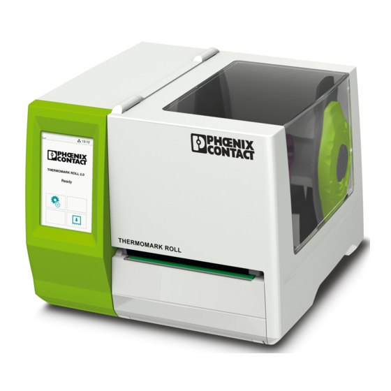
- Page 1 User manual UM EN THERMOMARK ROLL Thermal Transfer Printer for Labels and Continuous Media...
-
Page 2: User Manual
User manual Thermal Transfer Printer for Labels and Continuous Media 2012-01-30 Designation: UM EN THERMOMARK ROLL Version: Order No.: – This user manual is valid for: Designation Order no. THERMOMARK ROLL 5146477 THERMOMARK ROLL AR 5146749 104611_en_02 PHOENIX CONTACT... - Page 3 The receipt of technical documentation (in particular user documentation) does not constitute any further duty on the part of Phoenix Contact to fur- nish information on modifications to products and/or technical documenta- tion. You are responsible to verify the suitability and intended use of the products in your specific application, in particular with regard to observing the applicable standards and regulations.
- Page 4 THERMOMARK ROLL How to contact us Internet Up-to-date information on Phoenix Contact products and our Terms and Conditions can be found on the Internet at: www.phoenixcontact.com Make sure you always use the latest documentation. It can be downloaded at: www.phoenixcontact.net/catalog...
- Page 5 NOTE: Use suitable print media A low-quality ink ribbon can lead to premature wear on the printhead and result in a poor print image. Use only print media from Phoenix Contact. You can find suitable print media in the Phoenix Contact catalog.
-
Page 6: Technical Data
THERMOMARK ROLL Technical data Resolution 300 dpi x 300 dpi (12 points/mm x 12 points/mm) Print mode Thermal transfer 32 bit/400 MHz Material sensor Position Center Type Gap sensor Detection Label gap, black mark and punch-hole mark Print speed 30 mm/s … 125 mm/s... -
Page 7: Table Of Contents
Table of Contents Introduction ....................8 1.1 Product Description ......................8 1.2 Instructions ........................8 1.3 Intended Use ........................9 1.4 Safety Instructions ......................9 1.5 Environment ......................... 10 Installation ....................11 2.1 Device Overview ......................11 2.2 Unpacking and Setting-up the Printer ................13 2.3 Connecting the Device ....................14 2.3.1 Connecting to the Power Supply ................14 2.3.2 Connecting to a Computer via USB ................. -
Page 8: Introduction
Introduction 1.1 Product Description The device is an industrial thermal transfer printer for printing labels and continuous media. 1.2 Instructions Important information and instructions in this documentation are designated as follows: Danger! Draws your attention to an exceptionally grave, impending danger to your health or life. Warning! Indicates a hazardous situation that could lead to injuries or material damage. Attention! Draws attention to possible dangers, material damage or loss of quality. -
Page 9: Intended Use
Introduction 1.3 Intended Use • The device is manufactured in accordance with the current technological status and the recognized safety rules. However, danger to the life and limb of the user or third parties and/or damage to the device and other tangible assets can arise during use. • The device may only be used for its intended purpose and if it is in perfect working order, and it must be used with regard to safety and dangers as stated in the operating manual. • The device printer is intended exclusively for printing suitable materials. Any other use or use going beyond this shall be regarded as improper use. The manufacturer/supplier shall not be liable for damage resulting from unauthorized use; the user shall bear the risk alone. • Usage for the intended purpose also includes complying with the operating manual, including the manufacturer‘s maintenance recommendations and specifications. Notice! The complete documentation is included in the scope of delivery on DVD, and can also currently be found in the Internet. 1.4 Safety Instructions • The device is configured for voltages of 100 to 240 V AC. It only has to be plugged into a grounded socket. -
Page 10: Environment
Introduction • Unauthorized interference with electronic modules or their software can cause malfunctions. • Other unauthorized work on or modifications to the device can also endanger operational safety. • Always have service work done in a qualified workshop, where the personnel have the technical knowledge and tools required to do the necessary work. • There are various warning stickers on the device. They draw your attention to dangers. Warning stickers must therefore not be removed, as then you and other people cannot be aware of dangers and may be injured. • The maximum sound pressure level is less than 70 dB(A). Danger! Danger to life and limb from power supply. Do not open the device casing. 1.5 Environment Obsolete devices contain valuable recyclable materials that should be sent for recycling. Send to suitable collection points, separately from residual waste. The modular construction of the printer enables it to be easily disas- sembled into its component parts. -
Page 11: Installation
Installation 2.1 Device Overview 1 Cover 2 Margin stops 3 Roll retainer 4 Ribbon supply hub 5 Ribbon take-up hub 6 Belt roller 7 Print mechanics 8 Touchscreen display Fig. 1 Device with Tear-off Plate 9 Cutter or Perforation Cutter Fig. 2 Device with Cutter or Perforation Cutter... - Page 12 Installation 10 11 10 Label sensor 11 Printhead retainer with printhead 12 Print roller 13 Guides 14 Knob for adjusting the guides 15 Lever for locking the printhead 16 Tear-off plate Fig. 3 Print Mechanics...
-
Page 13: Unpacking And Setting-Up The Printer
Installation 2.2 Unpacking and Setting-up the Printer Lift the label printer out of the box and set it up on a level surface. Check label printer for damage which may have occurred during transport. Check delivery for completeness. Contents of Delivery: • Label Printer • Power Cable Type E+F • USB Cable • Operator's Manual • DVD with application software CLIP PROJECT, driver and documentation • Transfer ribbon • Continuous labels on roll Notice! Please keep the original packaging in case the printer must be returned. -
Page 14: Connecting The Device
Installation 2.3 Connecting the Device 1 Power switch 2 U SB master ports for keyboard, scanner, or memory stick 3 U SB high-speed slave port 4 E thernet 10/100 Base-T 5 Power connection jack Fig. 4 Connections 2.3.1 Connecting to the Power Supply The printer is equipped with a wide area power unit for a supply voltage of 100 V to 240 V. 1. Check that the device is switched off. 2. Plug the power cable into the power connection jack (5). 3. Plug the power cable into a grounded socket. -
Page 15: Connecting To A Computer Via Usb
Installation 2.3.2 Connecting to a Computer via USB Attention! Inadequate or no grounding can cause malfunctions during operations. Ensure that all computers and cables connected to the label printer are grounded. In order to connect the printer to a USB interface a printer driver must be installed. The adequate driver for your device can be found on the DVD included in the contents of delivery or on the internet at www.phoenixcontact.net/catalog. Switch on computer. Terminate all running tasks. ... -
Page 16: Switching On The Device
Installation 2.4 Switching on the Device When all connections have been made: Switch the printer on at the power switch (1). The printer performs a system test, and then shows the system status READY in the touch- screen display. If an error occurs during the system test, the symbol , Critical fault and type of error are Fig. 5 Power Switch displayed. -
Page 17: Touchscreen Display
Touchscreen Display 3.1 Structure of the Touchscreen Display The touchscreen display (1) indicates the current status of the printer and the print job, indicates faults and shows the printer settings READY in the menu. By selecting the buttons on the touchscreen display (1) settings can be made. Fig. 6 Touchscreen Display 3.2 Operating the Touchscreen Display The touchscreen display is operated directly by touch: • To open a menu or select a menu item lightly touch the corresponding symbol. • To scroll in lists slide finger up or down on the display. 3.3 Symbols on the Start Display Symbol Status Function Ready To offline menu Error Ready Feeds a blank label Ready... -
Page 18: Printer States
Touchscreen Display 3.4 Printer States State Display Description Ready Ready and the symbols The printer is in the ready state and can receive data or print labels. and Ready (after Ready and the symbols The printer is in the ready state and first print) can receive data. and Printing Label Label description and The printer is currently processing an the number of the printed active print job. label in the print job and Data can be transmitted for a new the symbols print job. The new print job will start when the and previous one has finished. Pause Pause The printing process has been inter- and the symbol rupted by the operator. -
Page 19: Configure Ethernet Interface
Touchscreen Display 3.5 Configure Ethernet Interface The Ethernet interface can be configured under menu item Setup > Interfaces. The following parameters are necessary for operating the printer in a network. Contact your network administrator if required. • IP address • Subnet mask • if necessary gateway Alternatively, the Ethernet configuration is also available via DHCP server. In this case, make sure that the transmitted configuration is always the same. Configure Ethernet interface at the printer Select Select Setup. Select Interfaces. Select Ethernet. Select setting options. Select desired setting with } |. Confirm selection with or cancel selection with ... -
Page 20: Loading Material
Loading Material 4.1 Loading Continuous Media from Roll Fig. 7 Loading Continuous Media from Roll 1. Turn ring (2) counterclockwise, so that the arrows points to the symbol and thus release the margin stop (1) from the roll retainer (4). 2. Load label roll (3) on the roll retainer (4) in such a way that the printing side of the labels is visible from above. 3. Re-mount the margin stop (1) and push against the label roll as far as possible. 4. Turn ring (2) clockwise, so that the arrow points to the symbol , and thus fix the margin stop(1) on the roll retainer (4). 5. Turn lever (8) counterclockwise to open printhead. 6. If the printer is equipped with a cutter or perforation cutter, fold it down. 7. Position guides (5) by turning the knob (7) so that they are several milli- meters wider than the material. 8. Position material below the belt roller (6) and guide it through the print unit. Attention! Guide material through the print unit below the label sensor (9). 9. Move guides (3) closely to the edges of the material without clamping the material. -
Page 21: Loading Fanfold Labels
Loading Material 4.2 Loading Fanfold Labels Fig. 8 Loading Fanfold Labels 1. Position label stack (1) behind the printer. 2. Guide material below the roll retainer (2) to the printing unit. Ensure that the printing side of the labels is visible from above. 3. Turn lever (6) counterclockwise to open printhead. 4. If the printer is equipped with a cutter or perforation cutter, fold it down. 5. Position guides (3) by turning the knob (5) so that they are several milli- meters wider than the material. 6. Position material below the belt roller (4) and guide it through the print unit. Attention! Guide material through the print unit below the label sensor (7). 7. Move guides (3) closely to the edges of the material without clamping the material. 8. If the printer is equipped with a cutter/perforation cutter, guide material through the cutter and fold cutter back to the printing unit. -
Page 22: Loading Transfer Ribbon
Loading Material 4.3 Loading Transfer Ribbon Fig. 9 Transfer Ribbon Feed Path Fig. 10 Guide Adjustment Notice! With direct thermal printing, do not load a transfer ribbon; if one has already been loaded, remove it. 1. Clean the printhead before loading the transfer ribbon ( 7.2 on page 28). 2. Turn lever (6) counterclockwise to open the printhead. 3. Set guide (1) on both hubs to the correct transfer ribbon width (Fig. 10): • Hold hub and unlock guide (1) by turning it in direction A. • Slide guide in direction B and adjust guide to ribbon width using the scale. • Hold hub and lock guide by turning it in direction C. - Page 23 Loading Material 7. Secure starting end of the transfer ribbon to the ribbon core (3) using adhesive tape. Ensure counterclockwise rotation direction of the transfer ribbon take-up hub. 8. Turn transfer ribbon take-up hub (2) counterclockwise to smooth out the feed path of the transfer ribbon. 9. Press printhead down and turn lever (6) clockwise to lock printhead.
-
Page 24: Cutter/Perforation Cutter
Option 5.1 Cutter/Perforation Cutter As an option a cutter (THERMOMARK ROLL-CUTTER, Art.-No.: 5146422), with which labels can be cut automatically is available. This cutter is also suitable for cutting endless labels. For marking sleeves a perforation cutter (THERMOMARK ROLL-CUTTER/P, Art.-No.: 5146435) is available. Dismount Tear-Off Plate Fig. 11 Dismount tear-off plate 1. Fold down cover (3) with tear-off plate (2) until the slot (4) at the latch-hook (5) is visible. 2. Lift cover (3) from the retainer (1). Mount Cutter/Perforation Cutter Fig. 12 Mount cutter/perforation cutter 3. First, put the latch-hook (10) of the cutter with the slot (9) into the guiding of the retainer (7). 4. Push cutter (6) down into the retainers (8) . 5. Fold up cutter (6) until it snaps in at both sides of the retainer (7). -
Page 25: External Supply Hub
Option 5.2 External Supply Hub As an option an external supply hub (THERMOMARK ROLL-ERH, Art.-No.: 5146448), with which media rolls with bigger diameters can be processed is available. Fig. 13 Load Material to External Supply Hub Mount External Supply Hub 1. Position External supply hub behind the printer. 2. Lift printer slightly and position ground plate (7) on both hooks (6) of the external supply hub. Load Material 1. Turn ring (2), so that the arrows points to the symbol , and thus release the margin stop (1) from the roll retainer (3). 2. Load label roll (4) on the roll retainer (3) in such a way that the printing side of the labels is visible from above. 3. Re-mount the margin stop (1) and push against the label roll as far as possible. 4. Turn ring (2) clockwise, so that the arrow points to the symbol , and thus fix the margin stop (1) on the roll retainer (3). 5. Adjust guide (5) of the printer to the material width. 6. Guide material over roll retainer of the printer and load into printing unit ( 4.1 on page 20). -
Page 26: Printing Operation
Printing Operation Attention! Printhead damage caused by improper handling! Do not touch the underside of the printhead with the fingers or sharp objects. Ensure that the labels are clean. The printer is ready for operation when all connections have been made and labels and the transfer ribbon have been loaded. 6.1 Printing in Tear-off Mode After printing the label is torn-off manually. For this the printer is equipped with a tear-off plate. 6.2 Printing in Cutting Mode The printer version with cutter or perforation cutter is used to cut off or perforate labels and endless material automatically after printing. -
Page 27: Cleaning
Cleaning 7.1 Cleaning Instructions Danger! Risk of death via electric shock! Disconnect the printer from the power supply before performing any maintenance work. It is important to clean the thermal printhead regularly. This guarantees a consistently good printed image and reduces wear of the printhead. Attention! The printer can be damaged by aggressive cleansers. Do not use abrasive cleaners or solvents for cleaning the external surfaces or modules. -
Page 28: Cleaning The Printhead
Cleaning 7.2 Cleaning the Printhead Cleaning intervals: direct thermal printing - every media roll change thermal transfer printing - every ribbon roll change Substances may accumulate on the printhead during printing and adversely affect printing. Attention! Printhead can be damaged! Do not use sharp or hard objects to clean the printhead. Do not touch protective glass layer of the printhead. Attention! Risk of injury from the hot printhead line. -
Page 29: Cleaning Or Replacing The Print Roller
Cleaning 7.3 Cleaning or Replacing the Print Roller Accumulations of dirt on the print roller may impair the media transport and the print quality. Attention! Damage of the print roller. Do not use sharp objects (knives, screwdrivers, etc.) to clean the printhead. Notice! When large amounts of narrow and thick media (10 mm profiles, narrow endless shrink sleeve) are used, the print roller might be deformed and a result in a worsened printing for labels. -
Page 30: Cleaning Cutter/Perforation Cutter And Replace Blades
Cleaning 7.4 Cleaning Cutter/Perforation Cutter and Replace Blades Warning! Disconnect printer from electrical outlet to prevent accidental blade movement. Warning! Risk of injury! The cutter blades are sharp! Notice! When cutting through the label material instead of the label gap remains of adhesive may accumulate on the blades. - Page 31 Cleaning Fig. 17 Replace Blades Fig. 18 Springs 4. If the blades are very dirty with residues of adhesive or if they are worn, change blades: Turn shaft (6) clockwise using a torx wrench TX10 until the gear racks (7) cannot engage anymore. Pull upper blade (9) out of the guides (8). Take out lower blade (10). Remove deposits on the blades with label remover and a soft cloth. If necessary, replace blades. Push lower blade down into the guides (11). If necessary, put springs (12) back into spring retainers (13). To re-mount the upper blade push lower blade down on the cover and push upper blade into the guide until the gear racks (7) can engage with the gear wheels (5). Turn shaft (6) counterclockwise using a torx wrench TX10 until the blade reaches the upper limit. 5. Fit blade unit (3) according to Fig. 16 into the axes (2) and fold it towards the cover (4) until it snaps in. 6. Fold cutter/perforation cutter up to the print unit.
-
Page 32: Fault Correction
Fault Correction 8.1 Problem Solution Problem Cause Remedy Print image has smears or Printhead is dirty Clean the printhead voids 7.2 on page 28 Print roller is dirty Clean the print roller 7.3 on page 29 Print roller is worn/ Change the print roller damaged 7.3 on page 29 Printer transports labels but Transfer ribbon inserted Check transfer ribbon does not print them. incorrectly feed path and orientation of the coated side and correct if necessary. Clean the printhead 7.2 on page 28 Table 3 Problem Solution... -
Page 33: Error Messages And Fault Correction
Fault Correction 8.2 Error Messages and Fault Correction Error message Cause Remedy Out of Out of transfer ribbon Insert new transfer ribbon. ribbon Cancel current print job. Transfer ribbon melted during Change the heat level via printing software. Clean the printhead 7.2 on page 28 Load transfer ribbon Restart print job. Cancel current print job. The printer is loaded with Set software to direct thermal thermal labels, but the printing. software is set to transfer Restart print job. printing Device not Programming addresses a Either connect this optional conn. non-existent optional device device or correct the programming. - Page 34 Fault Correction Error message Cause Remedy Cutter Cutter cannot return into its Switch off the printer. Remove blocked home position and stays in material. Switch on the printer. an undefined position Restart print job. Material too thick or hard, Check material cutter does not cut through material but can return to initial position. No cutter function Switch the printer off and then on. If error recurs call service. Network e.g. No DHCP server, no Please contact your network Error link, no SMTP server, no administrator. Timeserver Out of paper Out of label roll Load labels. Error in the paper feed, Check paper feed. Material is not positioned under the label sensor. Protocol Printer has received an Select to skip the...
-
Page 35: Licences
Licences 9.1 EC Declaration of Conformity... - Page 36 Licences...
-
Page 37: Fcc
Written Offer to GPL Source Code: Whereas such specific license terms entitle you to the source code of such software, PHOENIX CONTACT will provide upon written request via email and/or traditional paper mail the applicable GPL source code files via CD-ROM for a nominal cost to cover shipping and media charges as allowed under the GPL and LGPL. -
Page 38: Index
Index Cleaning Recycling ......10 Printhead .....28 Print Roller ....29 Connecting ......14 Safety Instructions ....9 Contents of Delivery ..13 Service Work .....10 Critical error .......18 Setting-up ......13 Supply Voltage....14 Switching on the Device ..16 Device Overview....11 Symbols ......17 Environment ......10 Tear-off Mode ....26 Error Touchscreen Display ..17 Correction ....33 Messages ....33 State ......18 Unpacking......13 Important information...8 Warning Stickers ....10 Instructions ......8 Intended Use .......9 Lithium Battery....10 Loading Continuous Media from Roll ....20 Loading Fanfold Labels ..21 Loading Material ....20...
Need help?
Do you have a question about the THERMOMARK ROLL and is the answer not in the manual?
Questions and answers